
Related Manuals for Lowrance LVR-250


Summary of Contents for Lowrance LVR-250
- Page 1 Pub. 988-0158-051 www.lowrance.com LVR-250 VHF Radio Installation and Operation Instructions...
-
Page 2: Important Safety Information
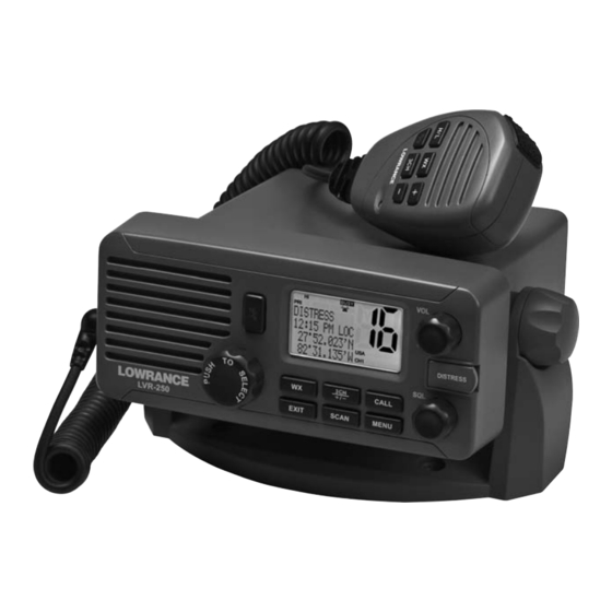
We reserve the right to do so without notice. All features and specifications subject to change without notice. All screens in this manual are simulated. On the cover: LVR-250 shown. Other models covered For free owner’s manuals and the most current information on this product, its operation and accessories, visit our web site: www.lowrance.com... -
Page 3: Table Of Contents
2-3 Local or Distance Sensitivity (LOCAL/DIST) ... 22 2-3-1 Set Distance Sensitivity ...22 2-3-2 Set Local Sensitivity ...22 2-4 Backlighting (BACKLIGHT) and Contrast (CONTRAST) ... 22 2-4-1 Set the Backlighting Level ...23 2.4.2 Set the Contrast Level ...23 Lowrance - LVR-250 Installation and Operation Instructions... - Page 4 4-5 ATIS MMSI & ATIS Functionality... 32 4-5-1 Enter or Edit YOUR ATIS MMSI ...33 4-5-2 Enable ATIS Functionality (ATIS FUNC) LVR-250 EU ONLY ...33 4-6 DSC functionality options (DSC FUNC) ... 34 4-7 Response Type to LL Polling Calls (LL REPLY) ... 34 Section 5 - Sending and Receiving DSC Calls ...35...
- Page 5 Appendix D - EU Inland Waterway Channels ...55 D-1 Special Channels Appendix E - MMSI and License Information ...59 FCC Compliance ...59 Navico Full Two-Year Lowrance VHF Warranty ...60 How to Obtain Service ...61 Lowrance - LVR-250 Installation and Operation Instructions ... 58...
-
Page 6: Installation
There are two ways to install the radio. You can choose: • A deck or overhead mounted gimbal installation to a suitable site and the radio is placed into it. The radio can be removed for storage and the viewing angle can be adjusted. •... -
Page 7: Checklist
Four plain washers for the mounting gimbal Four nuts for the mounting gimbal Lowrance - LVR-250 Installation and Operation Instructions Not pictured: Two plastic stoppers for the recessed installation. Installation template. One 7 Amp spare fuse in case of accidental reverse of battery polarity. -
Page 8: Gimbal Installation
The viewing angle on the gimbal mount has a 20º tilt range. To change the current viewing angle on the gimbal mount: Support the radio, then cautiously loosen the mounting knobs until the radio can be moved. Re-position the radio then tighten the mounting knobs again. -
Page 9: Install The Microphone Bulkhead Mount
If your bulkhead exceeds 0.51” (13mm), the stopper can be discarded if necessary. Tighten the M5x32 screws until the radio is held firmly against the rear of the bulkhead. Install the Microphone Bulkhead Mount Hold the microphone bulkhead mount at the... -
Page 10: Fix The Dsc Label
Fix the DSC label A DSC warning label is supplied with the LVR-250. To comply with FCC regulations, this warning label must be affixed in a location that is clearly visible from the operating con- trols of this Lowrance radio. Make sure that the chosen location is clean and dry before applying this label. -
Page 11: Set Up The Radio
If you don’t have a user MMSI contact the appropriate authorities in your country. If you’re unsure who to contact, consult your Lowrance dealer. Enter Your User MMSI Refer to 4.2 Enter your user MMSI. Lowrance - LVR-250 Installation and Operation Instructions Function No connection OUT (+) -
Page 12: The Completed Installation
The Completed Installation External speaker GPS product VHF Antenna External speaker connection cable Antenna connection cable Black Fuse power on Red cable power cable Battery Base unit with microphone Lowrance - LVR-250 Installation and Operation Instructions... -
Page 13: Notes
Notes: Lowrance - LVR-250 Installation and Operation Instructions... -
Page 14: Section 1 - General Information
Section 1 - General Information 1-1 Features Congratulations on your purchase of a Lowrance LVR-250 marine band VHF radio. It provides the following useful features: • Prominent channel display • Adjustable contrast settings for the LCD • Adjustable keypad backlighting for easy night-time use •... -
Page 15: Customizing Your Lowrance Vhf Radio
1-2 Customizing your Lowrance VHF Radio You can customize the radio to suit your individual preferences. Some preferences can be set directly through the keys as explained in this Section. Other preferences are set up through the built-in menus and these are explained in the other Sections. - Page 16 Shows which of the 3 favourite channels, if any, are selected. Otherwise blank. ATIS LVR-250 EU only, and enabled for radios in European inland waterways. A typical operational display is shown here. The latitude and longitude of the vessel and the local time are shown.
-
Page 17: Basic Operation And Key Functions
The default is Channel 16. To make Channel 09 the priority channel, hold down 16/9 until a beep sounds and 09 is displayed. Priority Channel. LVR-250 EU only. Also on the microphone. Press to cancel all other modes and to tune into the priority channel. Channel 16, on high power. - Page 18 Weather Channel. LVR-250 US only. In USA and Canadian waters, press to hear the most recently selected weather station. The WX symbol is displayed on the LCD. Rotate the dial or + / - on the microphone to change to a different weather channel.
- Page 19 EXIT to exit from a menu without saving changes, and to back up to the previ- ous screen. Radio and DSC Call Menu. Press to enter the DSC Call Menu and make CALL DSC calls. See Section 6. DSC Setup Menu. Press to enter the DSC Setup Menu and to customize MENU your radio.
-
Page 20: Section 2 - The Radio Menu (Menu)
DSC SETUP RADIO SETUP GPS SIM RESET Sections 1-3 and 1-4 explain how to navigate around the menu and enter, save and change data. Lowrance - LVR-250 Installation and Operation Instructions MANUAL SETTING USER MMSI GROUP SETUP INDIV REPLY ATIS MMSI... -
Page 21: Maintain Your Buddy List (Buddy List)
Press ENT to store the changes. The buddy list is displayed again. If more changes are required, repeat Steps 2 through 6. Otherwise, press EXIT to ESC. Lowrance - LVR-250 Installation and Operation Instructions Use the Buddy List to store the names and associated MMSIs of 20 favourite people. -
Page 22: Delete An Entry
LOCAL is displayed on the LCD as a reminder that local sensitivity is selected. 2-4 Backlighting (BACKLIGHT) and Contrast (CONTRAST) MENU SELECT LOCAL/DIST >BACKLIGHT CONTRAST Lowrance - LVR-250 Installation and Operation Instructions EDIT MANUAL NEW >DELETE Use LOCAL/DIST to improve the sensitivity of the receiver either locally (LOCAL) or over distances (DIST). -
Page 23: Set The Backlighting Level
The vessel’s latitude and longitude are shown on the screen, with the UTC time. The prefix MAN indicates a manual entry. The manual entries are cancelled if a real GPS posi- tion is received. Lowrance - LVR-250 Installation and Operation Instructions Select BACKLIGHT. Select a comfortable backlight level using + or - to change the setting. -
Page 24: Local Time (Time Offset)
90°W 150°W 2-5-3 Time Format Options (TIME FORMAT) Time can be shown in 12 or 24 hour format. GPS/DATA MANUAL >SETTING Lowrance - LVR-250 Installation and Operation Instructions SETTING >TIME OFFSET TIME FORMAT TIME DISPLY ‡ Standard Time Universal Time... -
Page 25: Time Display Options (Time Display)
SETTING TIME DISPLY LL DISPLY >COG/SOG If COG/SOG is set ON (on), the time is not displayed on the screen (see section 2-5-4). Lowrance - LVR-250 Installation and Operation Instructions TIME DISPLY >OFF LL DISPLAY >OFF COG/SOG >ON Select GPS/DATA, then SETTING. -
Page 26: Gps Alert Options (Alert)
>GPS ALERT 2-6 GPS Simulator (SIMULATOR) The GPS Simulator is set to OFF whenever the radio is turned ON or whenever real GPS data is available through the COM port. However, if you want to test it, turn it on. -
Page 27: Section 3 - Radio Setup Menu (Radio Setup)
LCD along with the last used channel. All the channel charts are shown in Appendix C. RADIO SETUP >UIC CH NAME RING VOLUME Lowrance - LVR-250 Installation and Operation Instructions Channel band. See Section 3-2. Edit or delete channel names. See Section 3-3. Set the volume level of the incoming call notification beeps. -
Page 28: Channel Names (Ch Name)
Press ENT to enable the new volume setting and return to the menu. 3-5 Internal Speaker Connections (INT SPEAKER) Switch the radio’s internal speaker ON (on) or OFF (off ). The external speaker is always ON (on) if a speaker is plugged into the external speaker jack. -
Page 29: Set The Priority Channel (Watch Mode)
>INT SPEAKER 3-6 Set the Priority Channel (WATCH MODE) If you have LVR-250 EU, watch mode is similar to a dual watch, scanning between the priority channel and the working channel. CH16 is the priority channel, however if you have LVR-250... -
Page 30: Section 4 - Dsc Setup Menu (Dsc Setup)
Enter or change the name and/or details of a group. GROUP SETUP See section 4-3. Choose an automatic or manual response to calls. (LVR-250 US only) INDIV REPLY See section 4-4. Enter or change your ATIS MMSI (LVR-250 EU only) ATIS MMSI See section 4-5. -
Page 31: Maintain Your Groups (Group Setup)
- to scroll to the incorrect entry then press ENT. Press ENT to edit. The group name details are displayed, with the cursor at the first character of the name. Lowrance - LVR-250 Installation and Operation Instructions GROUP NAME ––––––––––––... -
Page 32: Delete A Group
ATIS sends a digital message any time that you release the PTT key. Inland waterways rules require 1 W Tx power on Channels 06, 08, 10, 11, 12, 13, 14, 15, 17, 71, 72, 74 and 77. Lowrance - LVR-250 Installation and Operation Instructions DELETE GROUP... -
Page 33: Enter Or Edit Your Atis Mmsi
You can view your stored ATIS MMSI at anytime by selecting ATIS MMSI in the main menu 4-5-2 Enable ATIS Functionality (ATIS FUNC) LVR-250 EU ONLY ATIS functionality will operate only after the ATIS MMSI has been entered (see previous sec- tion). -
Page 34: Dsc Functionality Options (Dsc Func)
DSC is operational, if the ATIS annunciator is shown, ATIS is operational. 4-7 Response Type to LL Polling Calls (LL REPLY) You can set up the radio to respond to an LL polling request in one of three ways: AUTO Automatically replies to any incoming LL polling requests from any of your buddies. -
Page 35: Section 5 - Sending And Receiving Dsc Calls
Section 5 - Sending and Receiving DSC Calls A valid USER MMSI must be entered into this radio before these DSC functions can be used. See 4-2 Enter Your USER MMSI (USER MMSI). 5-1 What is DSC? DSC (Digital Selective Calling) is a semi-automated method of establishing VHF, MF, and HF radio calls. -
Page 36: Make A Routine Call (Individual)
The radio summarizes the call details and asks for confirmation to send the call (SEND?). Press ENT to send the call. The radio goes to CH70 and the Tx annunciator is displayed on the screen while the DSC call is being sent. -
Page 37: Acknowledgement Of An Individual Incoming Call (Indiv)
Alternating ROUTINE ENT –> ACK The LVR-250 EU requires the operator to manually send an acknowledgement to the request- ing radio. Press ENT to send an acknowledgement or EXIT to cancel. The LVR-250 US will automatically send an acknowledgement to the requesting radio within 10 seconds of receiving the call. -
Page 38: Call All Ships (All Ships)
>URGENCY GROUP >ALL SHIPS The ALL SHIPS ROUTINE call option is shown on the LVR-250 US. Press CALL to enter DSC mode, then select ALL SHIPS. The priority is set automatically to URGENCY. However, you can select one of the... -
Page 39: Call Using The Distress Log (Dist Log)
MMSI of the vessel in Distress, the second screen shows the nature of the emergency (if specified) and the MMSI of the vessel that relayed the Distress Call. Lowrance - LVR-250 Installation and Operation Instructions 02 REBECCA T DISTRESS... -
Page 40: Request The Ll Position Of A Buddy (Ll Request)
AWAITING ACK The working channel name is displayed while the radio waits for an acknowledgement from your buddy. If there is no reply after 1 minute the radio asks if you want to retry. Continue as explained in Section 5-2-2. -
Page 41: Receiving Dsc Calls
Press ENT to switch to the designated working channel manually; press EXIT to return to old CH. The priority level and the user MMSI are displayed on the screen. If the radio recognises the user MMSI as one of your buddies, the buddy’s name is displayed in place of the user MMSI. -
Page 42: Receiving A Group Call (Group)
Press ENT. The user MMSI or name are displayed on the screen. If the radio recognises the user MMSI as one of your buddies, the buddy’s name is displayed in place of the user MMSI. -
Page 43: Section 6 - Distress Calls
Section 6 - Distress Calls A valid USER MMSI must be entered into this radio before these DSC functions can be used. See 4-2 Enter Your USER MMSI (USER MMSI). 6-1 Sending a Distress Call DISTRESS CALL >FIRE FLOODING COLLISION Open the red cover labelled DISTRESS. -
Page 44: Receiving A Distress Call (Distress!)
(if specified). If the location and time are not specified, these are replaced with sequences of 9s and 8s respectively. The LVR-250 is capable of receiving enhanced LL position data if the vessel trans- mitting the Distress Call is sending this. This provides the position of the distressed vessel to within 20 m (60ft). -
Page 45: Appendix A - Technical Specifications
FSTN SO-239 (50 ohm) -20ºC to +50ºC (-4ºF to 120ºF) - LVR-250 US only -15ºC to +55ºC (5ºF to 130ºF) - LVR-250 EU onl y JIS-7 161(W) x 75(H) x 147(D) mm - without bracket 1.29 kg (2.8 lbs) - without microphone... - Page 46 +/- 5kHz better than 2.5µ W Less than 4%@ 1kHz for a +/-3kHz deviation 156.025 - 163.275 MHz 0.25uV (distant) / 2.5uV (local) for LVR-250 US 0.25uV (distant) / 0.8uV (local) for LVR-250 EU 0.35uV more than 65db more than 65 db...
-
Page 47: Appendix B - Troubleshooting
Check that the GPS cable is physically connected. Check the polarity of the GPS cable. Check the baud rate setting of the GPS if applicable. The baud rate setting should be 4800 and parity should be set to NONE. Lowrance - LVR-250 Installation and Operation Instructions... -
Page 48: Appendix C - Vhf Marine Channel Charts
161.850 157.300 161.900 157.350 161.950 157.400 162.000 156.025 160.625 156.075 160.675 Lowrance - LVR-250 Installation and Operation Instructions TRAFFIC TYPE Public Correspondence Public Correspondence Public Correspondence Port Operations Port Operations, Selected VTS Areas Inter-ship Safety Port Operations Commercial (inter-ship only) -
Page 49: Special Notes On International Channel Usage
This channel is only available on DSC enabled radios. Note: The INTERNATIONAL mode is not legal for use in U.S. or Canada waters. KEY: S = Simplex operating channel; D = Duplex operating channel. Lowrance - LVR-250 Installation and Operation Instructions Port Operations Port Operations... -
Page 50: Usa Channel Chart
156.175 156.175 156.225 156.225 156.275 156.275 156.325 156.325 Lowrance - LVR-250 Installation and Operation Instructions TRAFFIC TYPE Port Operations, Selected VTS Areas US Government, Coast Guard Port Operations, Selected VTS Areas Inter-ship Safety Commercial Commercial (inter-ship only) Recreational Calling Channel... -
Page 51: Special Notes On Usa Channel Usage
Distress, Safety, and Ship Calls. No voice communication is allowed on CH70. This channel is only available on DSC enabled radios. KEY: S = Simplex operating channel; D = Duplex operating channel. Lowrance - LVR-250 Installation and Operation Instructions Commercial, bridge-to-bridge, 1W with Power-up... -
Page 52: Canada Channel Chart
161.850 157.300 161.900 157.350 161.950 157.400 162.000 162.000 156.025 160.625 156.075 156.075 Lowrance - LVR-250 Installation and Operation Instructions TRAFFIC TYPE Public Correspondence Public Correspondence Public Correspondence Canadian Coast Guard, SAR Port Operations, VTS in Selected Areas Inter-ship Safety Commercial... -
Page 53: Special Notes On Canada Channel Usage
Lightly shaded simplex channels 21A, 23A, 61A, 64A, 81A, 82A, and 83A cannot be lawfully used in Canada waters unless special authorization is obtained from the Canadian Coast Guard. Not for use by the general public. Lowrance - LVR-250 Installation and Operation Instructions Canadian Coast Guard Public Correspondence, Duplex U.S. -
Page 54: Weather Channels
162.500 WX07 162.525 WX08 161.650 WX09 161.775 WX10 163.275 Lowrance - LVR-250 Installation and Operation Instructions TRAFFIC TYPE NOAA Weather Channel NOAA Weather Channel NOAA Weather Channel NOAA Weather Channel NOAA Weather Channel NOAA Weather Channel NOAA Weather Channel CANADIAN Weather Channel... -
Page 55: Appendix D - Eu Inland Waterway Channels
156.5 156.525 156.55 156.575 156.6 a) r) 156.625 156.65 f) g) 156.675 156.7 156.725 156.75 156.775 156.8 Lowrance - LVR-250 Installation and Operation Instructions TRANSMITTING SHIP-TO-SHIP FREQUENCY (MHZ) SHIP LAND 160.625 160.65 160.675 160.7 160.725 160.75 160.775 160.8 160.825 160.85 160.875... - Page 56 -sys tems by traffic centres. In some countries, frequencies certain channels are used for an other service catego- ry or other radio services. These countries are Austria, Bulgaria, Croatia, the Federal Republic of Yugosla via, Hun gary, Moldova, Romania, the Russian Federation, the Slovak Republic, the Czech Republic (with exemption of channels 08, 09, 72, 74 and 86), Ukraine and the Federal Republic of Yugosla via.
- Page 57 After permission of the competent authority, this channel may be used only for spe cial events on a temporary basis. In the Czech Republic this channel is used for service category nautical information. In the Czech Republic this channel is used for service category ship-to-port authorities. Lowrance - LVR-250 Installation and Operation Instructions...
-
Page 58: Special Channels
Lightly Shaded Simplex channel CH00 is only available in the UK to Coast Guard users with written authorization. The special channels above maybe fitted to your radio. These are only licensed for use in the country indicated. No attempt should be made to use them in any other country. -
Page 59: Appendix E - Mmsi And License Information
Appendix E - MMSI and License Information You must obtain a user MMSI (Marine Mobile Service Identity) and enter it into your LVR-250 in order to use the DSC functions. Contact the appropriate authorities in your country. If you are unsure who to contact, consult your Lowrance dealer. -
Page 60: Navico Full Two-Year Lowrance Vhf Warranty
REMINDER: You must retain the sales slip or sales receipt proving the date of your original purchase in case warranty service is ever required. NAVICO, 12000 E. SKELLY DRIVE, TULSA, OK 74128, (800) 324-1356 Lowrance - LVR-250 Installation and Operation Instructions... -
Page 61: How To Obtain Service
If you have technical, return or repair questions, contact the dealer in the country where you purchased your unit. To locate an Lowrance dealer near you, visit our web site or consult your telephone directory for listings. Lowrance - LVR-250 Installation and Operation Instructions 800-324-1356 800-661-3983 905-629-1614 (not toll-free) www.lowrance.com... - Page 62 Write the Return Authorization (RA) number on the outside of the box underneath your return address. For your security, you may want to insure the package through your shipping courier. Lowrance does not assume responsibility for goods lost or damaged in transit. Lowrance - LVR-250 Installation and Operation Instructions...
- Page 63 Notes:...
- Page 64 Copyright © 2008 Lowrance Pub. 988-0158-051 All Rights Reserved Printed in China - 100708 Navico 0560 MN000794B-G...
Need help?
Do you have a question about the LVR-250 and is the answer not in the manual?
Questions and answers