Table of Contents
Advertisement
Quick Links
Advertisement
Table of Contents

Related Manuals for McGrath Locks MLSJ8015


Summary of Contents for McGrath Locks MLSJ8015
- Page 1 MLSJ8015...
-
Page 2: Specifications
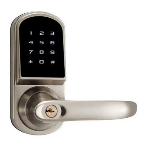
MLSJ8015 Description This 4 in 1 digital lock uses a tubular latch 70mm or 60mm. A stylish lock with a Bluetooth App, pin code, RFID card and manual key to provide quick and convenient access. Specifications ▪ Unlocking methods: Bluetooth App, RFID Card, Pass code, Wristband or Key ▪... -
Page 3: System Specifications
MLSJ8015 System Specifications Connectivity Bluetooth 4.0, Wi-Fi (Wi-Fi Bridge required) Case Material Aluminium Alloy Identification Mode TTLock App, Card (Mifare 13.56 MHz), Code and Bluetooth IP Rating IP65 User Capacity Finish Satin Nickel or Black Identification Time Instant recognition under 0.3 seconds... - Page 4 INFORMATION AND SAFTY WARNINGS : 1.1 Introduction: This user manual will guide you through the functions and usages of our MLSJ8015 Bluetooth enabled smart lock. It is important that you follow the instructions and regard all notes that appear throughout this manual.
-
Page 5: Door Preparation
MLSJ8015 Door Preparation Packing List 1. Check door thickness and Door Frame. Door frame≧110mm Door thickness: 38-50mm 2. Check door open direction. 1. Door drill hole map... - Page 6 MLSJ8015 A) Outdoor lock body * 1 H) Cylindrical sleeve female bolt *2 B) Silicon gasket * 2 I) 80mm length Square spindle *1 C) Mounting plate * 1 J) M4 x 30mm cross flat head bolt * 3 D) Indoor lock body * 1...
-
Page 7: Installation Diagram
MLSJ8015 Installation Diagram Step 1 Step 2 According to the map drilling holes on the door. Install the deadbolt (E). Note: The single latch has TWO backset options:60mm or 70mm, please adjust it by yourself. Note: 1) Check the required backset (60mm or 70mm). - Page 8 MLSJ8015 Installation Diagram Step 3 Step 4 Install outdoor unit(A) with F & H. Install outdoor unite with gasket(B) & spindle(I) on the door, Pin(G) is for fixing spindle(I). Note: Cylindrical sleeve bolt F is not a must if your door doesn't have a hole for it.
- Page 9 MLSJ8015 Installation Diagram Step 5 Step 6 Install indoor unit(D) on the door. Install mounting plate (C) with gasket(B) on the door. Note: Cable goes under the latch. Note: Push cable into the hole at first. Note: Install 4 pieces AA...
-
Page 10: System Reset
MLSJ8015 Installation Diagram System Reset Step 7 The reset button is on the backside of back panel, right behind the number 4 on the touchpad. Keep pressing the reset button with a Testing the lock by rotating back handle and using key(M). - Page 11 MLSJ8015 Lock Boxes Galvanised Alloy Stainless Steel lockbox Note. Both lock boxes are sold separately and need to ne welded onto the gate.
- Page 12 MLSJ8015...
Need help?
Do you have a question about the MLSJ8015 and is the answer not in the manual?
Questions and answers