Table of Contents
Advertisement
Advertisement
Table of Contents

Related Manuals for MicroCool IBEX Series


Summary of Contents for MicroCool IBEX Series
- Page 1 IBEX SERIES 1-3 GPM 2020 Installation & Maintenance Manual Version 06.20 MicroCool 72216 Northshore Street #103-104, Thousand Palms, CA 92276, USA www.microcool.com Phone: +1-760-322-1111 info@microcool.com Fax: +1-760-343-1820 SMALL FRAME_June 2020 June 20 Page 1 of 41 IBEX 8 Nozzle...
-
Page 2: Table Of Contents
IBEX pump modules ..........9 Principle of the VFD system on the IBEX pump unit ..............9 VARIABLE FREQUENCY DRIVE ............................. 9 MicroCool IBEX - STARTING THE SYSTEM ................... 10 START UP ..................................10 PRESSURIZING THE SYSTEM ...................... 11 SMALL FRAME_June 2020... - Page 3 System Operation ........................12 Time Clock ....................................13 Setting Date & Time ................................13 Setting Auxiliary Parameters ............................13 Drain/Pressure Relief Valve Time ..............................13 Setting Drain Valve Time..............................13 24 Hour, 7 Day Clock Time ................................ 14 Setting 24 Hour, 7 Day Clock Timers ..........................14 Setting Cycle/Pulse Timer ..............................
- Page 4 IBEX 1-3 GALLON REAR VIEW ............................31 IBEX 1-3 GALLON RIGHT SIDE VIEW ..........................32 IBEX 1-3 GALLON LEFT SIDE VIEW ............................. 33 IBEX 1-3 GALLON TOP VIEW.............................. 34 IBEX 1-3 GALLON INTERNAL TOP VIEW ..........................35 IBEX 1-3 GALLON BOTTOM VIEW ............................. 36 IBEX 1-3 GALLON 240V CONTROL PANEL ..........................
-
Page 5: Before Starting
WARNING!! PLEASE TAKE NOTE OF THE FOLLOWING 1. BEFORE STARTING PLEASE READ THIS GUIDE ENTIRELY BEFORE BEGINNING INSTALLATION ALSO, READ SUPPLEMENTAL INFORMATION RELATING TO OPTIONAL CONTROL EQUIPMENT CRANKCASE OIL PLUG The pump module crankcase vent has been plugged to prevent accidental oil leakage during shipment. Remove the plug and replace with the supplied vent cap before operating pump unit. -
Page 6: Water Quality
WATER QUALITY 2. WATER QUALITY To obtain the best performance, special consideration should be given to the quality of water used in a MicroCool fog system. For more information about Water Quality, consult a MicroCool specialist. MicroCool IS NOT RESPONSIBLE FOR NOZZLE BLOCKAGE DUE TO POOR WATER QUALITY. -
Page 7: Installation Of The Pump Module
3. INSTALLATION OF THE PUMP MODULE Installation Procedure: Determine pump module location • Identify water supply/connection for the system • Determine routing of the high pressure manifold from the pump. • Establish drainage location from the pump. • Verify correct electrical power supply to the pump. •... -
Page 8: Pump Module Power Supply
4.2.1 The circuit to the pump module must be dedicated and properly sized to carry the electrical load placed upon it by the pump motor. Please refer to the MicroCool Engineering Manual or electrical data plate on the motor to determine the amperage draw of the Ibex pump module. -
Page 9: Dc Voltage From Pump Controller
WARNING: The control box is completely wired for immediate operation. After high voltage wiring is connected and the unit is supplied with proper water pressure, pressing F1 will immediately activate the pump operation. 5. Standard wiring diagrams for MicroCool IBEX pump modules ... -
Page 10: Microcool Ibex - Starting The System
6.1.5 For more details on the VFD drive, the readings and fault status, refer to the WEG Drive supplement at the end of this manual. 7. MicroCool IBEX - STARTING THE SYSTEM START UP 7.1.1 Install UV bulb prior to start up. (If UV is provided) 7.1.2 The system must be primed and flushed before pressurization. -
Page 11: Pressurizing The System
8. PRESSURIZING THE SYSTEM ABOUT PRESSURE REGULATOR The regulator is set as a safety valve should the system pressure exceed IBEX: 1,100 PSI (75.8 Bar). At extremely low flow, the regulator will bypass water back into the pump head as the VFD drive has reached its minimum Frequency (Hertz). -
Page 12: System Operation
9. System Operation F1 – Manual Run F2 – Auto Ready F3 – Stop/Reset F4 – Use to access parameter settings (hold for 3 seconds) ESC – Exit existing screen OK – Enter/Save F1 – Manual Run F1 operates the pump manually, the pump will run continuously regardless of external controllers or internal time settings. -
Page 13: Time Clock
Time Clock The internal time clock needs to be set to the correct local time. Setting Date & Time 1. Press and hold F4 for three seconds. 2. Display screen will change to day, time and date. 3. Press “ESC” once. 4. -
Page 14: Hour, 7 Day Clock Time
24 Hour, 7 Day Clock Time The controller contains of three 24 hour, 7 day time clocks that can be set to start and stop the pump unit on pre-set days and times as required. Special care should be taken to not program conflicting times. 9.4 Setting 24 Hour, 7 Day Clock Timers 1. -
Page 15: Setting Internal Temperature And Humidity Controls (Optional Upgrade)
Setting Internal Temperature and Humidity Controls (Optional Upgrade) 1. If this upgrade was ordered with the system, temperature and humidity control will be available in the controller. 2. To access, enable and set the temperature and humidity control, follow the steps in "Setting Auxiliary Parameters”... - Page 16 1. First turn the black panel latch counter clockwise to release. 2. Using a flat screw driver turn the black screw release counter clockwise about 1/8” and hold it in that position. 3. Pull the door open with the red disconnect switch in the vertical position. 4.
- Page 17 MicroCool® FOCUS Pump Information Screens Home Screen MicroCool Pump • Software version • Hours of operation • Keypad Functions • F1- Press to run manual F2- Press to run in auto (requires external • contact) F3- Stop/ Reset • F4- Hold for 3 seconds to enter parameter •...
- Page 18 One Shot Run Pump is running in “Auto” mode. • One shot timer is active and counting • down. System pressure. • Hours of operation • Control Parameters Current temperature • Temperature set point • Current humidity • Humidity set point •...
- Page 19 Pressure Relief Pump has stopped and is draining • System pressure • Drain Time • Auto Cycle Run Pump is running on cycle time • • On timer System pressure • Hours of Operation • Auto Start Delay • Auto Start Active •...
- Page 20 Inlet Pressure Fault • Inlet water pressure dropped below safe operating limit • 30 second restart delay is in process • If water pressure is restored within 30 second delay, pump will start up and operate normally If water pressure is not restored, another •...
- Page 21 Lockout Fault- Inlet Pressure Pump system has faulted out on a low • water pressure fault. Restore water pressure to the pump. • Press F3 to reset • Lockout Fault – High Water Temp. • Pump system has faulted on high water temperature fault.
-
Page 22: System Maintenance
P56, P59 Giant PumpSeries Figure 20 – Crankcase Oil Levels ELECTRICAL MOTOR SERVICE Two types of electrical motors are used on the MicroCool pump modules. Some small motors have sealed rotor bearings and some require lubrication periodically. Refer to the motor nameplate for the type of motor. If the motor is equipped with external grease nipples refer to the chart below for lubrication instructions. -
Page 23: Inlet Water Filters
INLET WATER FILTERS The inlet water filter cartridges, 5-micron and 10-micron, must be inspected once per week or as needed. The change interval of the filter cartridges depends entirely upon the cleanliness of the inlet water. When the “outlet gauge” shows a significant drop in pressure during operation it is time to change the filters. -
Page 24: Optional Extras
OPTIONAL EXTRAS ULTRAVIOLET FILTER (UV): High Intensity Light to kill bacteria and germs. CAUTION: DO NOT DIRECTLY LOOK AT THE UV LIGHT AS EYE DAMAGE MAY OCCUR The UV light filter is shipped with the UV bulb in a separate protective tube. The bulb is installed prior to starting the pump unit. -
Page 25: Trouble Shooting
11. TROUBLE SHOOTING PUMP MODULE HAS STOPPED RUNNING Pump system has faulted out due to loss in supply water pressure or VFD fault. Pump will try re-start in 30 seconds. If the water pressure has not been restored, or the VFD fault automatically re-set, the pump system will remain off for another 30 seconds. -
Page 26: Variable Frequency Drive (Vfd) Fault Codes
VARIABLE FREQUENCY DRIVE (VFD) FAULT CODES DRIVE DESCRIPTION POSSIBLE CAUSES DISPLAY F0021 • Wrong voltage supply; check if the data on the inverter label complies with the power supply and parameter PO296. Supply voltage too low, producing • voltage on the DC link below the Undervoltage fault on the intermediate circuit. - Page 27 F0072 P0156, P0157, P0158 setting is too • low in relation to the motor operating Motor overload fault (60 s in 1.5xlnom) current. Overload on the motor shaft • F0074 Ground overcurrent fault. Short-circuit to the ground in one or •...
-
Page 28: Warranty
MicroCool warrants that the goods to be delivered will be of the kind and quality described in the sales order or contract, and will be free of defects in workmanship or material. Should any failure to conform to this warranty... -
Page 29: Ul Certification
Certificate Numbe r E352513-20120418 Report Reference E352513-20120418 Report Reference 2019- MARCH-07 Issue Date 2015- MARCH-26 Issue Date MICROCOOL Issued to: MICROCOOL Issued to: 72216 Northshore St. Unit 103-104 30670 HILL ST THOUSAND PALMS CA 92276 THOUSAND PALMS CA 92276 INDUSTRIAL CONTROL PANELS... -
Page 30: Ibex 1-3 Gallon Illustrations
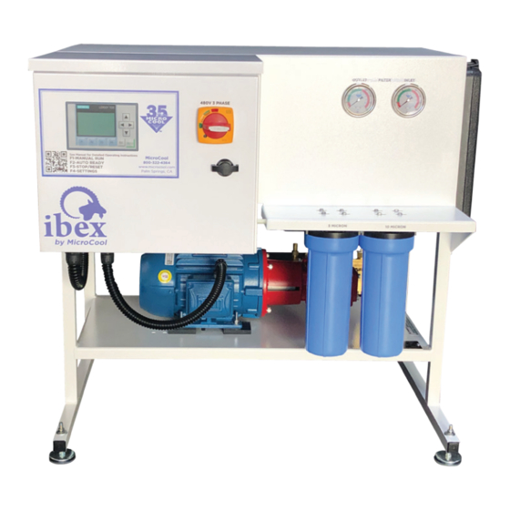
14. IBEX 1-3 Gallon Illustrations IBEX 1-3 GALLON FRONT VIEW SMALL FRAME_June 2020 June 20 Page 30 of 41 IBEX 8 Nozzle... -
Page 31: Ibex 1-3 Gallon Rear View
IBEX 1-3 GALLON REAR VIEW SMALL FRAME_June 2020 June 20 Page 31 of 41 IBEX 8 Nozzle... -
Page 32: Ibex 1-3 Gallon Right Side View
IBEX 1-3 GALLON RIGHT SIDE VIEW SMALL FRAME_June 2020 June 20 Page 32 of 41 IBEX 8 Nozzle... -
Page 33: Ibex 1-3 Gallon Left Side View
IBEX 1-3 GALLON LEFT SIDE VIEW SMALL FRAME_June 2020 June 20 Page 33 of 41 IBEX 8 Nozzle... -
Page 34: Ibex 1-3 Gallon Top View
IBEX 1-3 GALLON TOP VIEW SMALL FRAME_June 2020 June 20 Page 34 of 41 IBEX 8 Nozzle... -
Page 35: Ibex 1-3 Gallon Internal Top View
IBEX 1-3 GALLON INTERNAL TOP VIEW SMALL FRAME_June 2020 June 20 Page 35 of 41 IBEX 8 Nozzle... -
Page 36: Ibex 1-3 Gallon Bottom View
IBEX 1-3 GALLON BOTTOM VIEW SMALL FRAME_June 2020 June 20 Page 36 of 41 IBEX 8 Nozzle... -
Page 37: Ibex 1-3 Gallon 240V Control Panel
IBEX 1-3 GALLON 240V CONTROL PANEL SMALL FRAME_June 2020 June 20 Page 37 of 41 IBEX 8 Nozzle... -
Page 38: Ibex 1-3 Gallon 480V Control Panel
IBEX 1-3 GALLON 480V CONTROL PANEL SMALL FRAME_June 2020 June 20 Page 38 of 41 IBEX 8 Nozzle... -
Page 39: Ibex 1-3 Gallon Notes 1
IBEX 1-3 GALLON NOTES 1 SMALL FRAME_June 2020 June 20 Page 39 of 41 IBEX 8 Nozzle... -
Page 40: Ibex 1-3 Gallon Notes 2
IBEX 1-3 GALLON NOTES 2 SMALL FRAME_June 2020 June 20 Page 40 of 41 IBEX 8 Nozzle... -
Page 41: Ibex 1-3 Gallon 208-240V Electrical Diagram
IBEX 1-3 GALLON 208-240V ELECTRICAL DIAGRAM SMALL FRAME_June 2020 June 20 Page 41 of 41 IBEX 8 Nozzle...
Need help?
Do you have a question about the IBEX Series and is the answer not in the manual?
Questions and answers