Table of Contents
Advertisement
Quick Links
Advertisement
Table of Contents

Related Manuals for DigiBird VWC2-ROC


Summary of Contents for DigiBird VWC2-ROC
- Page 1 DigiBird Technology VWC2-ROC Video Wall Controller User Manual V1.0...
-
Page 2: Table Of Contents
Table of Contents 3.2.4. Video Wall Mode Setting ..11 About This Manual ........I 3.3. Video Wall Layout......12 Conventions ..........I 3.3.1. Create Windows ....12 Hardware ........... 1 3.3.2. Switching Signal ....14 1.1. Overview ........1 3.3.3. - Page 3 4.3.1. Add User ....... 28 4.3.2. Revise User Information ..28 4.3.3. Delete User ......29 4.4. Controller Management ....29 4.5. Backup & Restore ......30 4.5.1. Backup ........30 4.5.2. Restore ......... 30 - 2 -...
-
Page 4: About This Manual
About This Manual Thank you for purchasing DigiBird products. This manual is provided to help you get the most from your VWC2-ROC series controller. It covers all respects of configuration and operation. This manual may subject to change without prior notice. -
Page 5: Hardware
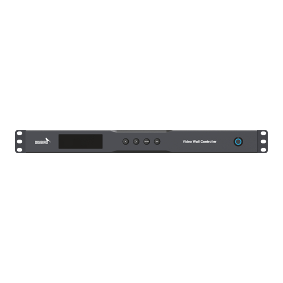
Hardware 1. Hardware 1.1. Overview VWC2-ROC is a compact video wall controller which delivers 4k/60 visual experiences. Up to 4x input sources can be displayed simultaneously to LCD wall or LED wall with any size and at any position. With capabilities to support embedded audio, VWC2-ROC offers higher flexibility for versatile applications, such as meeting rooms, small control rooms and digital signage. -
Page 6: Modify Ip Via Front Panel
Hardware 4x HDMI input, 12x HDMI output, 1x Lan for control, 1x Support modify IP address via push button Lan for preview 1.3. Modify IP via front panel User can obtain and modify IP address over push button at front panel. Operation Initial Press any... -
Page 7: Software
2.2.2. OS requirements Microsoft Windows OS requirements as below: Notes Windows XP 32/64 Windows 7 32/64 Windows 8 32/64 Windows 10 32/64 2.3. Software installation 2.3.1. Software installation Download software from DigiBird website and install software by following the wizard. -
Page 8: Software Interface
Software 2.4. Software Interface With user-friendly interface, you can easily manage video wall display. Interface description Item Description Menu Bar Including Main, Setting and Tools Tools Bar Tools to achieve different functions Input Display all inputs in list or thumbnail Virtual VW Virtual video wall corresponding physical video wall Status... -
Page 9: Software Operation
Operation 3. Software Operation 3.1. Communication After successfully log in, a window will pop out if failed to communicate with controller. Click Confirm to start setting, or click Cancel to enter into DEMO mode. Your control PC can establish connection with controller via serial port or network. Default connection is UDP communication. - Page 10 Operation Besides of input IP manually, you can also search controller IP address. Enable Network Setting Click Find IP to find all controllers within network. Select target controller Confirm to complete setting. If no controller has been detected, please ensure whether PC IP and controller IP within same network.
-
Page 11: Revise Ip Address
Operation COM port should be vacant. 3.1.2. Revise IP Address 3.1.2.1. LAN Communication Select Network Setting, click Find IP to view all controllers within the LAN. Select target controller and click Advanced. Input new IP address and click Revise 3.1.2.2. Serial Port Communication Connect controller to your control PC via serial cable. -
Page 12: Video Wall Configuration
Operation 3.2. Video Wall Configuration 3.2.1. Create New Video Wall Connect controller to video wall correctly via video cable. Navigate to Setup and Click Video Wall. Configure video wall parameters at Video Wall Configuration. Refer 3.3.3 Parameter for more details. Allocate output channel to corresponding screen. -
Page 13: Output Channel Setting
Operation Parameter Below table is description of parameter. Screen Resolution Select desired screen resolution. Support customized resolution. Refer 3.2.4 Screen Resolution Setting for more details. Video Wall Input video wall Rows and Columns Sub Screen Virtual sub screen of physical screen to help locate window position. -
Page 14: Customized Resolution
Operation • To change mapping relationship between output channel and screen, you need to select target screen and double click target output channel. Apply Auto Pair to pair unconfigured channel to available screen. 3.2.3. Customized Resolution If offered resolution in library can not meet demand, user can customize resolution upon demand. 3.2.3.1. -
Page 15: Video Wall Mode Setting
Operation 3.2.4. Video Wall Mode Setting 3.2.4.1. LCD Mode For LCD and DLP video wall, please select LCD wall mode. Under this mode, you can input bezel information by pixel as bezel compensation to ensure the whole image is unified to avoid image tearing and distortion. -
Page 16: Video Wall Layout
Operation As LED display areas, which are powered by sending card, are not same, need to apply LED Mode to configure. Select one screen and set up Row height and Column Width Row height of screen indicates the row height where screen located in pixel. Column width of screen indicates the column width where screen located in pixel. - Page 17 Operation Overlay Creating. If you want to create a window on existing window, please press <Ctrl> and arbitrary create window. Single Screen. Select one input, drag it to virtual video wall and release. The window will auto fit the screen which your mouse was located.
-
Page 18: Switching Signal
Operation Precisely Creating. Select target input, Click New, and complete required information. Window parameters are descried in below table. Parameter Description Name Display input source name Coordinates To locate window position by pixel. Take left top corner as valid. Size et window height and width 3.3.2. -
Page 19: Windows Operating
Operation 3.3.3. Windows Operating Basic window operation includes Set Top, Set Bottom, Resize, Clear, etc. 3.3.3.1. Window Button Through 4x buttons of top right corner, you can manage window display. Button description as shown in below table. Button Description Zoom in this window to fit for occupied sub screen. Zoom in this window to full screen. - Page 20 Operation Right click to call out setting menu: Options Description Set window to top Bottom Set window to bottom Move up by one layer Down Move down by one layer Locked Position Window can not be moved Group Select multiple windows and group them Lock the aspect Remain aspect ratio when resizing ratio...
- Page 21 Operation Button Description Create new window Close Close selected window or group of windows. Clear Close all windows on the video wall Lock Click to freeze window, click again to unlock Set selected window to top Bottom Set selected window to bottom Properties To edit window properties Input To check input resolutions...
-
Page 22: Layout Management
Operation 3.4. Layout Management Video wall display, including window position, size, layer order and input properties, can be saved as layout. That information will be stored in hardware and maximum support 64x layouts. 3.4.1. Save Save current display as layout. Input preset ID and save. If preset ID has been occupied before, new layout will auto replace previous one. -
Page 23: Refresh
Operation 3.4.3. Refresh Click Refresh to reload window information from controller. 3.4.4. Management Click Management to call out preset management window. -
Page 24: Layout Circle
Operation Setting instructions as below: Options Description Icon Select icon for layout Add to toolbar Add selected preset to tool bar, easy to recall. Name Edit preset name Delete Delete selected layout Hotkey Set up hotkey for quick recall Auto Circle Enable circle for selected layout Interval Set up intervals for layout... - Page 25 Operation System supports turn on/off audio, volume adjustment and audio output model setting. Navigate to Main Menu, and click Audio to enter into setting page. Click output channel to switch audio output via 3.5mm mini-jack. Volume can be adjusted by dragging audio bar.
-
Page 26: Input Source Setting
Operation Green indicates audio of this input source has been activated Click to activate current audio. Red indicates audio has been disabled. Click again can enable it. 3.6. Input Source Setting Select one input from Input Source List, right click call out setting menu. 3.6.1. -
Page 27: Source Cutting
Operation 3.6.2. Source Cutting When you want to emphasize certain part of image or current aspect ratio is not perfect, you can cut input source. To cut input source, need to define which part to be cut off by inputting pixel information. - Page 28 Operation Item Description Show Input Label Enable to display label Position Distance to left top corner by pixel Click to select color from drop-down list or click to select desired Label Color color from color plate. Background Color To add background color for station logo. Text logo Select text logo, type logo title, select font and size.
-
Page 29: Background Color
Operation 3.6.4. Background color If there is no valid input, user can set up background color for window that displaying on video wall. 3.7. Matrix Switch To conduct matrix function, controller need to be configured as matrix mode, please refer 3.2.5 Video Wall Setting 3.7.1. -
Page 30: Clear Video
Operation Source not supported under matrix mode. 3.7.2. Clear Video Right click output channel and select Clear video to delete current displaying signal. 3.7.3. Rename Right click output channel, and select Rename. -
Page 31: System Management
System Management 4. System Management 4.1. Preview Setting For the model that supports preview, use can live preview input source content and video wall display. Default IP of preview card is 192.168.1.201. Follow below steps to revise IP address. Navigate to Setting, and click Preview to enter into setting page. Enter desired IP address, subnet mask and gateway. -
Page 32: Read Edid
System Management 4.2.1. Read EDID Select target input or output, click Read EDID and select local folder to save EDID file. 4.2.2. Write EDID Select targeted input channel, click Write EDID and import EDID file. 4.3. User Management Default password of Admin account is blank. Navigate to Setting, click User to enter into setting page. -
Page 33: Delete User
System Management 4.3.3. Delete User Select desired user, click Delete and confirm to execute. 4.4. Controller Management This software can manage multiple controllers at a time. Navigate to Main Menu and click Management to enter into setting page. Click Add and input controller IP. You can also set up hotkey for the controller. -
Page 34: Backup & Restore
System Management Newly added controller will show up as shortcut, click icon to manage this controller. 4.5. Backup & Restore 4.5.1. Backup Navigate to Tools, click Back Up and save configuration file to your local PC. 4.5.2. Restore Navigate to Tools, click Restoration and confirm to continue. Select corresponding file and import file. - Page 35 DigiBird Technology Co., Ltd. www.digibirdtech.com sales@digibirdtech.com...
Need help?
Do you have a question about the VWC2-ROC and is the answer not in the manual?
Questions and answers