
Related Manuals for Dell Precision 3460 Small Form Factor


Summary of Contents for Dell Precision 3460 Small Form Factor
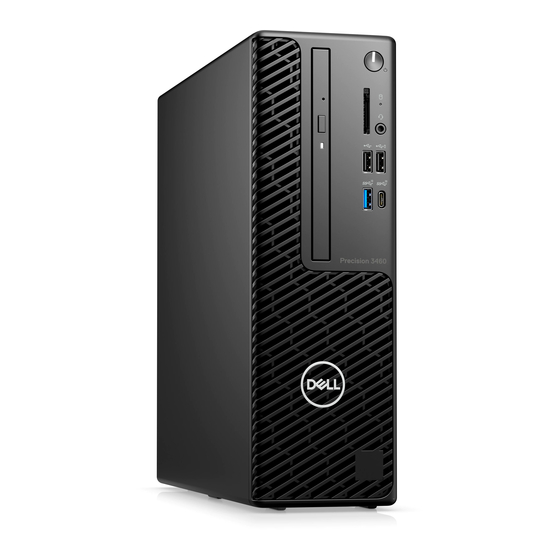
- Page 1 Precision 3460 Small Form Factor Service Manual Regulatory Model: D17S Regulatory Type: D17S004 March 2022 Rev. A00...
- Page 2 A WARNING indicates a potential for property damage, personal injury, or death. © 2022 Dell Inc. or its subsidiaries. All rights reserved. Dell, EMC, and other trademarks are trademarks of Dell Inc. or its subsidiaries. Other trademarks may be trademarks of their respective owners.
-
Page 3: Table Of Contents
After working inside your computer..........................9 Chapter 2: Removing and installing components................10 Recommended tools................................10 Screw list..................................... 10 Major components of Precision 3460 Small Form Factor..................11 Side cover.................................... 13 Removing the side cover............................13 Installing the side cover.............................. 14 Front bezel...................................14 Removing the front bezel............................14... - Page 4 Optional I/O modules (PS2/Serial)..........................68 Removing optional PS2 module..........................68 Installing optional PS2 module..........................69 System board..................................71 System board callouts - Precision 3460 Small Form Factor................71 Removing the system board............................71 Installing the system board............................74 Chapter 3: Software........................78 Drivers and downloads..............................
- Page 5 Diagnostic LED behavior..............................95 Recovering the operating system..........................96 Updating the BIOS in Windows............................96 Updating the BIOS using the USB drive in Windows....................97 Backup media and recovery options..........................97 WiFi power cycle................................97 Chapter 6: Getting help and contacting Dell................98 Contents...
-
Page 6: Chapter 1: Working Inside Your Computer
You should only perform troubleshooting and repairs as authorized or directed by the Dell technical assistance team. Damage due to servicing that is not authorized by Dell is not covered by your warranty. See the safety instructions that is shipped with the product or at www.dell.com/regulatory_compliance. -
Page 7: Safety Precautions
ESD protection is an increasing concern. Due to the increased density of semiconductors used in recent Dell products, the sensitivity to static damage is now higher than in previous Dell products. For this reason, some previously approved methods of handling parts are no longer applicable. -
Page 8: Esd Field Service Kit
It is recommended that all field service technicians use the traditional wired ESD grounding wrist strap and protective anti-static mat at all times when servicing Dell products. In addition, it is critical that technicians keep sensitive parts separate from all insulator parts while performing service and that they use anti-static bags for transporting sensitive components. -
Page 9: Transporting Sensitive Components
Transporting sensitive components When transporting ESD sensitive components such as replacement parts or parts to be returned to Dell, it is critical to place these parts in anti-static bags for safe transport. Lifting equipment Adhere to the following guidelines when lifting heavy weight equipment: CAUTION: Do not lift greater than 50 pounds. -
Page 10: Chapter 2: Removing And Installing Components
Removing and installing components NOTE: The images in this document may differ from your computer depending on the configuration you ordered. Recommended tools The procedures in this document may require the following tools: ● Phillips screwdriver #0 ● Phillips screwdriver #1 ●... -
Page 11: Major Components Of Precision 3460 Small Form Factor
Table 1. Screw list (continued) Component Screw type Quantity Screw image System board #6-32 Major components of Precision 3460 Small Form Factor The following image shows the major components of Precision 3460 Small Form Factor. Removing and installing components... - Page 12 Removing and installing components...
-
Page 13: Side Cover
17. Optical drive 18. Processor NOTE: Dell provides a list of components and their part numbers for the original system configuration purchased. These parts are available according to warranty coverages purchased by the customer. Contact your Dell sales representative for purchase options. -
Page 14: Installing The Side Cover
Installing the side cover Prerequisites If you are replacing a component, remove the existing component before performing the installation procedure. About this task The following images indicate the location of the side cover and provides a visual representation of the installation procedure. Steps 1. -
Page 15: Installing The Front Bezel
Steps 1. Pry the retention tabs to release the front bezel from the computer. 2. Slightly pull the front bezel and gently rotate to release the other tabs on the bezel from the slots in the computer chassis. 3. Remove the front bezel from the computer. Installing the front bezel Prerequisites If you are replacing a component, remove the existing component before performing the installation procedure. -
Page 16: Hard Drive
Steps 1. Position the front bezel to align the tabs on the bezel with the slots on the chassis. 2. Press the bezel until the tabs clicks into place. Next steps 1. Install the side cover. 2. Follow the procedure in after working inside your computer. - Page 17 Removing and installing components...
-
Page 18: Installing The 2.5-Inch Hard Drive
Steps 1. Disconnect the hard-drive data and power cables from the connectors on the hard drive and push the tab on the left towards the hard drive to free the caddy from the chassis 2. Release the hard drive caddy from the tabs on the chassis and slide the hard drive caddy out. 3. - Page 19 Removing and installing components...
-
Page 20: Removing The 3.5-Inch Hard Drive
Steps 1. Align the pins on the caddy with the slot on the hard-disk drive and insert the hard-disk drive into the caddy. 2. Pull the other end of the hard-disk drive caddy and insert the hard-disk drive into the slot. 3. - Page 21 About this task The following images indicate the location of the 3.5-inch hard drive and provide a visual representation of the removal procedure. Steps 1. Pull the two tabs from the hard-drive caddy away from the hard-drive. 2. Slide the hard-drive towards the right to free it from the mounting points on the caddy and lift it away from the system. 3.
-
Page 22: Installing The 3.5-Inch Hard Drive
4. Slide the hard-drive towards the right to free it from the mounting points on the caddy and lift it away from the system. Installing the 3.5-inch hard drive Prerequisites If you are replacing a component, remove the existing component before performing the installation procedure. About this task The following images indicate the location of the 3.5-inch hard drive and provides a visual representation of the installation procedure. -
Page 23: Hard-Drive And Optical-Drive Bracket
Steps 1. Align the hard-drive with the mounting points on the caddy and place the hard-drive onto it. 2. Pull the tabs on the right side of the caddy until the hard-drive clicks into place. 3. Place the tabs on the right side of the hard-drive caddy onto the holders on the chassis and push the left side of the caddy down until it clicks into place. -
Page 24: Installing The Hard-Drive And Optical-Drive Bracket
5. Remove the 3.5-inch hard-drive. About this task The following images indicate the location of the hard-drive and optical-drive bracket and provide a visual representation of the removal procedure. Steps 1. Remove the hard-drive power and data cables that are routed via the locking mechanism. 2. - Page 25 About this task The following images indicate the location of the hard-drive and optical-drive bracket and provides a visual representation of the installation procedure. Steps 1. Connect the power and SATA cables to the optical drive while holding the bracket upside down. 2.
-
Page 26: M.2 Solid-State Drive
M.2 solid-state drive Removing the M.2 2230 solid-state drive (slot-1) Prerequisites 1. Follow the procedure in before working inside your computer. 2. Remove the side cover. About this task The following images indicate the location of the solid-state drive and provide a visual representation of the removal procedure. Steps 1. -
Page 27: Removing The M.2 2230 Solid-State Drive (Slot-2)
Steps 1. Align the notch on the solid-state drive with the tab on the solid-state drive connector. 2. Insert the solid-state drive at a 45-degree angle into the slot on the system board. 3. Replace the screw (M2x3) to secure the solid-state drive to the system board. Next steps 1. -
Page 28: Installing The M.2 2230 Solid-State Drive (Slot-2)
Steps 1. Remove the screw (M2x3) that secures the solid-state drive to the system board. 2. Slide and lift the solid-state drive off the system board. Installing the M.2 2230 solid-state drive (slot-2) Prerequisites If you are replacing a component, remove the existing component before performing the installation procedure. About this task The following image indicates the location of the solid-state drive and provides a visual representation of the installation procedure. -
Page 29: Removing The M.2 2280 Solid-State Drive (Slot-1)
Steps 1. Align the solid-state drive with the socket on the system board and slide it in. 2. Replace the screw (M2X3) that secures the solid-state drive to the system board. Next steps 1. Install the hard-drive and optical-drive cage. 2. -
Page 30: Removing The M.2 2280 Solid-State Drive (Slot-3)
About this task The following images indicate the location of the solid-state drive and provides a visual representation of the installation procedure. Steps 1. Align the notch on the solid-state drive with the tab on the solid-state drive connector. 2. Insert the solid-state drive at a 45-degree angle into the slot on the system board. 3. -
Page 31: Installing The M.2 2280 Solid-State Drive (Slot-3)
Steps 1. Remove the screw (M2x3) that secures the solid-state drive to the system board. 2. Slide and lift the solid-state drive off the system board. Installing the M.2 2280 solid-state drive (slot-3) Prerequisites If you are replacing a component, remove the existing component before performing the installation procedure. About this task The following images indicate the location of the solid-state drive and provides a visual representation of the installation procedure. -
Page 32: Wlan Card
Steps 1. Align the solid-state drive with the socket on the system board and slide it in. 2. Replace the screw (M2X3) that secures the solid-state drive to the system board. Next steps 1. Install the hard-drive and optical-drive cage. 2. -
Page 33: Installing The Wlan Card
Steps 1. Remove the screw (M2x3) that secures the WLAN card to the system board. 2. Slide and lift the WLAN card bracket off the WLAN card. 3. Disconnect the antenna cables from the WLAN card. 4. Slide and remove the WLAN card from the connector on the system board. Installing the WLAN card Prerequisites If you are replacing a component, remove the existing component before performing the installation procedure. -
Page 34: Wlan Antenna
2. Place the WLAN card bracket to secure the WLAN antenna cables. 3. Insert the WLAN card into the connector on the system board. 4. Slide the wireless card at an angle into the wireless-card slot. 5. Replace the screw (M2x3) to secure the plastic tab to the WLAN card. Next steps 1. - Page 35 About this task The following image indicates the location of the WLAN antenna module and provide a visual representation of the removal procedure. Removing and installing components...
-
Page 36: Installing The Wlan Antenna
Steps 1. Remove the antenna cables from the routing guides on the chassis. 2. Remove the two (M2x3) screws that secures the WLAN antenna to the chassis. 3. Lift the WLAN antenna off the chassis. Installing the WLAN antenna Prerequisites If you are replacing a component, remove the existing component before performing the installation procedure. -
Page 37: Coin-Cell Battery
Steps 1. Route the antenna cables through the routing guides on the chassis. 2. Align and place the screw holes on the WLAN antenna with the screw holes on the chassis. 3. Replace the two screws (M3x5) to secure the WLAN antenna to the chassis. Next steps 1. -
Page 38: Installing The Coin-Cell Battery
About this task The following images indicate the location of the coin-cell battery and provide a visual representation of the removal procedure. Steps 1. Using a plastic scribe, gently pry the coin-cell battery out of the slot on the system board. 2. -
Page 39: Memory
Steps 1. Insert the coin cell battery with the "+" sign facing up and slide it under the securing tabs at the positive side of the connector. 2. Press the battery into the connector until it locks into place. Next steps 1. -
Page 40: Installing The Memory
Steps 1. Pull the tab and open the memory module door. 2. Pull the securing clips from both side of the memory module until the memory module pops up. 3. Lift and remove the memory module from the memory-module slot. Installing the memory Prerequisites If you are replacing a component, remove the existing component before performing the installation procedure. -
Page 41: Hard-Drive And Optical-Drive Supporting Bracket
Steps 1. Align the notch on the memory with the tab on the memory-module slot. 2. Slide the memory firmly into the slot and press the memory module down until it clicks into place. NOTE: If you do not hear the click, remove the memory module and reinstall it. 3. -
Page 42: Installing The Bay Support Bracket
2. Remove the side cover. 3. Remove the front bezel. 4. Remove the 2.5-inch hard-drive. 5. Remove the 3.5-inch hard-drive. 6. Remove the hard-drive and optical-drive cage. About this task The following images indicate the location of the Bay support bracket and provide a visual representation of the removal procedure. -
Page 43: Expansion Card
Steps 1. Insert the Bay support bracket at an angle into the slot on the chassis. 2. Align the screw holes and place the Bay support bracket on the slot on the chassis. 3. Replace the two screws (#6-32) to secure the Bay support bracket to the chassis. Next steps 1. -
Page 44: Installing The Graphics Card
Steps 1. Using the tab, lift and open the PCIe door. 2. Press down on the release tab and lift the graphics card off the system board. Installing the graphics card Prerequisites If you are replacing a component, remove the existing component before performing the installation procedure. About this task The following images indicate the location of the graphics card and provides a visual representation of the installation procedure. -
Page 45: Removing The Dell Ultra Speed Drive
4. Close the PCIe door. Next steps 1. Install the side cover. 2. Follow the procedure in after working inside your computer. Removing the Dell Ultra Speed Drive Prerequisites 1. Follow the procedure in before working inside your computer. 2. Remove the side cover. - Page 46 About this task The following images indicate the location of the Dell Ultra Speed Drive and provide a visual representation of the removal procedure. Removing and installing components...
- Page 47 Steps 1. Using the tab, lift and open the PCIe retainer latch. 2. Lift the Dell Ultra Speed Drive off the system board. 3. Flip over the Dell Ultra Speed Drive with SSD facing down. Removing and installing components...
-
Page 48: Installing The Dell Ultra Speed Drive
If you are replacing a component, remove the existing component before performing the installation procedure. About this task The following image indicates the location of the Dell Ultra Speed Drive and provides a visual representation of the installation procedure. Removing and installing components... - Page 49 Removing and installing components...
- Page 50 5. Align the Dell Ultra Speed Drive with the PCIe slot on the system board. 6. Using the alignment post on the PCIe slot, slide the Dell Ultra Speed Drive into the slot on the riser card until it clicks into place.
-
Page 51: Optical Drive
Optical drive Removing the optical drive Prerequisites 1. Follow the procedure in before working inside your computer. 2. Remove the side cover. 3. Remove the front bezel. 4. Remove the 2.5-inch hard-drive. 5. Remove the 3.5-inch hard-drive. 6. Remove the hard-drive and optical-drive cage. -
Page 52: Installing The Optical Drive
Installing the optical drive Prerequisites If you are replacing a component, remove the existing component before performing the installation procedure. About this task The following images indicate the location of the slim optical drive and provide a visual representation of the installation procedure. -
Page 53: Speakers
Speakers Removing the speaker Prerequisites 1. Follow the procedure in before working inside your computer. 2. Remove the side cover. About this task The following image indicates the location of the speaker and provide a visual representation of the removal procedure. Steps 1. -
Page 54: Processor Fan And Heat-Sink Assembly
Steps 1. Press the release tab and slide the speaker in the slot on the chassis until it snaps into place. 2. Route the speaker cable through the routing guide on the chassis. 3. Connect the speaker cable to the connector on the system board. Next steps 1. -
Page 55: Installing The Processor Fan And Heat-Sink Assembly
Steps 1. Disconnect the processor-fan cable from the connector on the system board. 2. In the reverse sequential order (4->3->2->1), loosen the four captive screws that secure the processor fan and heat-sink assembly to the system board. 3. Lift the processor fan and heat-sink assembly from the system board. Installing the processor fan and heat-sink assembly Prerequisites If you are replacing a component, remove the existing component before performing the installation procedure. -
Page 56: Processor
Steps 1. Align the screws on the processor fan and heat-sink assembly with the screw holders on the system board and place the processor fan and heat-sink assembly on the processor. 2. In the sequential order (1->2->3->4), tighten the captive screws to secure the processor fan and heat-sink assembly to the system board. -
Page 57: Installing The Processor
About this task The following images indicate the location of the processor and provide a visual representation of the removal procedure. Steps 1. Press down and push the release lever away from the processor to release it from the securing tab. 2. -
Page 58: Power-Supply Unit
Steps 1. Ensure that the release lever on the processor socket is fully extended in the open position. 2. Align the notches on the processor with the tabs on the processor socket and place the processor in the processor socket. NOTE: The pin-1 corner of the processor has a triangle that aligns with the triangle on the pin-1 corner on the processor socket. -
Page 59: Installing The Power-Supply Unit
Steps 1. Disconnect the power cables from the system board and unroute them from the routing guides on the chassis. 2. Remove the three screws (#6-32) that secure the power-supply unit to the chassis. 3. Slide the power-supply unit away from the back of the chassis. 4. - Page 60 Steps 1. Slide the power-supply unit into the chassis until the securing tab snaps into position. 2. Replace the three screws (#6-32) to secure the power-supply unit to the chassis. 3. Route the power cable through the routing guides on the chassis and connect the power cables to their respective connectors on the system board.
-
Page 61: Fan
Removing the chassis fan Prerequisites 1. Follow the procedure in before working inside your computer. 2. Remove the side cover. 3. Remove the front bezel. About this task The following images indicate the location of the chassis fan and provide a visual representation of the removal procedure. Steps 1. -
Page 62: Power Button
Steps 1. Insert the rubber grommets on the chassis. 2. Align the slots on the fan with the rubber grommets on the chassis. 3. Route the rubber grommets through the slots on the fan and pull the rubber grommets until the fan snaps into position. 4. -
Page 63: Installing The Power Button
Steps 1. Disconnect the power-button cable from the connector on the system board. 2. Press the release tabs on the power-button head and slide the power-button cable out from the front-side of the chassis. 3. Pull the power-button cable out from the computer. Installing the power button Prerequisites If you are replacing a component, remove the existing component before performing the installation procedure. -
Page 64: Intrusion Switch
Steps 1. Insert the power-button cable into the slot from the front-side of the computer, and press the power-button head until it clicks into the place in the chassis. 2. Align and connect the power-button cable to the connector on the system board. Next steps 1. -
Page 65: Installing The Intrusion Switch
Steps 1. Disconnect the intrusion switch cable from the connector on the system board. 2. Slide and lift the intrusion switch away from the chassis. Installing the intrusion switch Prerequisites If you are replacing a component, remove the existing component before performing the installation procedure. About this task The following image indicates the location of the intrusion switch and provides a visual representation of the installation procedure. -
Page 66: Sd-Card Reader
Steps 1. Insert the intrusion switch into its slot and slide the switch to secure it into the slot. 2. Connect the intrusion switch cable to the connector on the system board. Next steps 1. Install the side cover. 2. Follow the procedure in after working inside your computer. -
Page 67: Installing The Sd-Card Reader
Steps 1. Unroute the PSU cable from the routing guides on the SD-card reader bracket. 2. Remove the two screws (M3x5) that secure the SD-card bracket to the system board and computer. 3. Lift the SD-card reader from the connector on the system board. Installing the SD-card reader Prerequisites If you are replacing a component, remove the existing component before performing the installation procedure. -
Page 68: Optional I/O Modules (Ps2/Serial)
Steps 1. Place the SD-card reader onto the connector on the system board. 2. Install the two screws (M3x5) that secure the SD-card bracket to the system board and computer. 3. Reroute the cables through the routing guides on the SD-card reader bracket. Next steps 1. -
Page 69: Installing Optional Ps2 Module
Steps 1. Using the tab, lift and open the PCIe door. 2. Disconnect the PS2 module cable from the connector on the system board. 3. lift the PS2 module from the computer. Installing optional PS2 module Prerequisites If you are replacing a component, remove the existing component before performing the installation procedure. About this task The following images indicate the location of the optional PS2 module and provide a visual representation of the installation procedure. - Page 70 Steps 1. Align and insert the optional PS2 module with the slot on the chassis. 2. Connect the PS2 cable to the connector on the system board. 3. Close the PCIe door. Next steps 1. Install the heat-sink and fan assembly.
-
Page 71: System Board
System board System board callouts - Precision 3460 Small Form Factor 1. Intrusion switch connector 2. ATX CPU power connector 3. Power button connector 4. SD-card reader connector 5. M.2 WLAN connector 6. Memory module connector 7. SATA 1 connector 8. - Page 72 NOTE: Before disconnecting the cables from the system board, note the location of the connectors so that you can reconnect the cables correctly after you replace the system board. 2. Remove the side cover. 3. Remove the front bezel. 4. Remove the 2.5-inch hard-drive.
- Page 73 Removing and installing components...
-
Page 74: Installing The System Board
Steps 1. Remove the screw (#6-32) that secures the front I/O bracket to the chassis. 2. Lift the front I/O panel away from the chassis. 3. Disconnect all the cables from their connectors on the system board. 4. Remove the five screws (#6-32) that secure the system board to the chassis. 5. - Page 75 Removing and installing components...
- Page 76 Removing and installing components...
- Page 77 Steps 1. Align and lower the system board into the system until the stand-off points at the back of the system board align with those on the chassis. 2. Replace the five screws (#6-32) to secure the system board to the chassis. 3.
-
Page 78: Chapter 3: Software
This chapter details the supported operating systems along with instructions on how to install the drivers. Drivers and downloads When troubleshooting, downloading or installing drivers it is recommended that you read the Dell Knowledge Based article, Drivers and Downloads FAQ 000123347. -
Page 79: Chapter 4: System Setup
Boot menu Press <F12> when the Dell logo appears to initiate a one-time boot menu with a list of the valid boot devices for the system. Diagnostics and BIOS Setup options are also included in this menu. The devices listed on the boot menu depend on the bootable devices in the system. -
Page 80: Boot Sequence
Boot sequence enables you to bypass the System Setup–defined boot device order and boot directly to a specific device (for example: optical drive or hard drive). During the Power-on Self-Test (POST), when the Dell logo appears, you can: ● Access System Setup by pressing F2 key ●... - Page 81 Table 3. System setup options—System information menu (continued) Overview Memory Information Memory Installed Displays the total computer memory installed. Memory Available Displays the total computer memory available. Memory Speed Displays the memory speed. Memory Channel Mode Displays single or dual channel mode. Memory Technology Displays the technology that is used for the memory.
- Page 82 Table 4. System setup options—Boot Configuration menu (continued) Boot Configuration By default, the custom mode option is not enabled. Custom Mode Key Management Select the custom values for expert key management. Table 5. System setup options—Integrated Devices menu Integrated Devices Date/Time Displays the current date in MM/DD/YYYY format and current time in HH:MM:SS AM/PM format.
- Page 83 Table 6. System setup options—Storage menu (continued) Storage Device Displays the SATA HDD device information of the computer. SATA-1 Type Displays the SATA HDD type information of the computer. Device Displays the SATA HDD device information of the computer. SATA-2 Type Displays the SATA HDD type information of the computer.
- Page 84 Table 8. System setup options—Connection menu (continued) Connection Wireless Device Enable WLAN Enable or disable the internal WLAN device By default, the option enabled. Bluetooth Enable or disable the internal Bluetooth device By default, the option enabled. Enable UEFI Network Stack Enable or disable UEFI Network Stack and controls the on-board LAN Controller.
- Page 85 Table 10. System setup options—Security menu Security TPM 2.0 Security TPM 2.0 Security On Enable or disable TPM 2.0 security options. By default, the TPM 2.0 Security On option is enabled. Attestation Enable Enables to control whether the Trusted Platform Module (TPM) Endorsement Hierarchy is available to the operating system.
- Page 86 Allow Non-Admin PSID Revert Enable Allow Non-Admin PSID Revert Controls access to the Physical Security ID (PSID) revert of NVMe hard-drives from the Dell Security Manager prompt. By default, the option is disabled. Table 12. System setup options—Update, Recovery menu...
- Page 87 By default, the option is enabled. Dell Auto OS Recovery Threshold Controls the automatic boot flow for SupportAssist System Resolution Console and for Dell OS Recovery Tool. By default, the threshold value is set to 2. Table 13. System setup options—System Management menu...
- Page 88 Table 14. System setup options—Keyboard menu (continued) Keyboard Device Configuration Hotkey Access Device Configuration Hotkey Access Enable or disable users to access device configuration by using hotkeys. By default, the option is enabled. Table 15. System setup options—Pre-boot Behavior menu Pre-boot Behavior Warning and Errors Enable or disable the action to be done when a warning or error is encountered.
-
Page 89: Updating The Bios
Steps 1. Go to www.dell.com/support. 2. Click Product support. In the Search support box, enter the Service Tag of your computer, and then click Search. NOTE: If you do not have the Service Tag, use the SupportAssist feature to automatically identify your computer. You can also use the product ID or manually browse for your computer model. -
Page 90: Updating The Bios Using The Usb Drive In Windows
One-Time boot menu on the computer. Most of the Dell computers built after 2012 have this capability, and you can confirm by booting your computer to the F12 One-Time Boot Menu to see if BIOS FLASH UPDATE is listed as a boot option for your computer. If the option is listed, then the BIOS supports this BIOS update option. -
Page 91: System And Setup Password
Steps 1. From a turn off state, insert the USB drive where you copied the flash into a USB port of the computer. 2. Turn on the computer and press F12 to access the One-Time Boot Menu, select BIOS Update using the mouse or arrow keys then press Enter. -
Page 92: Deleting Or Changing An Existing System Setup Password
Deleting or changing an existing system setup password Prerequisites Ensure that the Password Status is Unlocked (in the System Setup) before attempting to delete or change the existing System and Setup password. You cannot delete or change an existing System or Setup password, if the Password Status is Locked. -
Page 93: Chapter 5: Troubleshooting
● Systems with 2.5-inch/ 3.5-inch Hard drives take longer to enter Modern Standby for the first time. System can enter Modern Standby normally from the second time onwards. ● Graphics Cards or Add-In Cards not factory installed by Dell may not be Modern Standby compliant and would not allow the system to enter Modern Standby. -
Page 94: Supportassist Diagnostics
Thermal pad for solid-state drive While replacing the serviceable system board, you can reuse the nonadhesive thermal pad for solid-state drive from the old system board. Intel System Agent Enhanced Speed Step (SAGV) always disabled All systems will have SAGV disabled by default. If enabled, systems will incur additional boot time when memory is added or swapped. -
Page 95: Diagnostic Led Behavior
Blinking pattern Amber White Problem description Suggested resolution Unrecoverable SPI Flash Failure CPU failure ● Run the Dell Support Assist/Dell Diagnostics tool. ● If problem persists, replace the system board. System board failure (included ● Flash latest BIOS version BIOS corruption or ROM ●... -
Page 96: Recovering The Operating System
It enables you to diagnose hardware issues, repair your computer, back up your files, or restore your computer to its factory state. You can also download it from the Dell Support website to troubleshoot and fix your computer when it fails to boot into their primary operating system due to software or hardware failures. -
Page 97: Updating The Bios Using The Usb Drive In Windows
Backup media and recovery options It is recommended to create a recovery drive to troubleshoot and fix problems that may occur with Windows. Dell proposes multiple options for recovering Windows operating system on your Dell PC. For more information. see... -
Page 98: Chapter 6: Getting Help And Contacting Dell
Getting help and contacting Dell Self-help resources You can get information and help on Dell products and services using these self-help resources: Table 22. Self-help resources Self-help resources Resource location Information about Dell products and services www.dell.com My Dell app...