Table of Contents
Advertisement
Quick Links
SERVICE MANUAL
September, 1 985
System
Video recording system
Rotary two heads,
Helical scanning FM system
Audio recording system
Rotary head, FM system
NTSC color, EIA standards
Video signal
8 mm video format cassette
Usable cassettes
SP: Approx. 1.43 cm/sec
Tape speed
Recording time
2 hr. (P6-120)
Image device
CCD (Charge Coupled Device)
Viewfinder
OV F
Lens
f= 15 mm, F1.6
3 positions zone focus
Depth of field*
focus
mark
indoors
po i nt
1.5
1.2-2.0
.s.
(4.9)
(3.9-6.6)
2.4
1.7-4.2
..
.
(7.9)
(5.6-13.8)
6.0
2.9-oo
.t
(19.7)
(9.5-oo)
3200 °
4
Color temperature
:
5800 °
•
:
Minimum illumination
25 lux (2.3 footcandles)
Illumination range
25-100,000 lux
(2.3-9,294 footcandles)
Recommended illumination
More than 300 lux
(28 footcandles)
Microphone
Input -66 dBs,
Electret condenser
microphone
•
SPECIFICATIONS
m(feet)
sunny
cloudy
day
day
0.9-4.5
0.6-oo
(3.0-14.8)
(2.0-oo)
0.8-oo
1.2-
00
(3.9-oo)
(2.6-oo)
1.7-oo
1.0-oo
(3.3 - oo)
(5.6-oo)
K
K
Canadian
General
Power requirements 6 V de
Power consumption
5.2 W
Operating temperature
o·c to 40°C (32°F to 104°F)
Storage temperature
-20°c to +60°c
(-4°F to +140°F)
Approx. 61
Dimensions
excluding the grip
Approx. 107
including the grip
Approx. 1.0 kg (2 lbs 3 oz)
Weight
excluding the battery and
cassette
Approx. 1.37 kg (3 lbs)
including the battery and
cassette
Accessories supplied
Shoulder strap (1)
Design and specifications are subject to change
without notice.
*When the FOCUS switch has been set to one
the three marks, an object within the range shown
the list will be in focus.
EJ
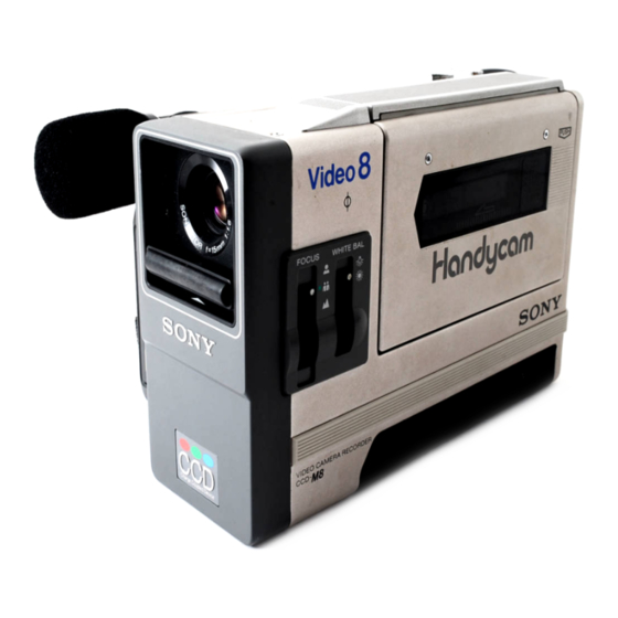
VIDE O CAM ERA REC ORD ER
SONY
us
Model
Model
CCD-MBu
E Model
CCD-MB
Video 8
109
173 mm
x
x
7
8
(21/,
43/a
6
/
in.)
x
x
(w / h/d)
109
215 mm
x
x
(41/.
43/a
81/2 in.)
x
x
(w/h/d)
of
i n
Advertisement
Chapters
Table of Contents

Subscribe to Our Youtube Channel
Related Manuals for Sony CCD-M8U


Summary of Contents for Sony CCD-M8U
- Page 1 (2.3-9,294 footcandles) the list will be in focus. Recommended illumination More than 300 lux (28 footcandles) VIDE O CAM ERA REC ORD ER Microphone Input -66 dBs, Electret condenser microphone SONY •...
- Page 2 ET LA LISTE DES SAFE OPERATION. REPLACE THESE COMPONENTS SONT CRITIQUES POUR CURIT WITH SONY PARTS WHOSE PART NUMBERS APPEAR FONCTIONNEMENT. REMPLACER COMPO AS SHOWN IN THIS MANUAL OR IN SUPPLEMENTS SANTS SONY DONT PUBLISHED BY SONY. CIRCUIT ADJUSTMENTS THAT...
-
Page 3: Table Of Contents
TAB L E OF CONTE NTS Title Page Se c tion Title Section GENERAL SCHEMATIC DIAGRAMS AND PRINTED WIRING BOARDS 1 -1 . Loc a t i o n a n d Fu n c t i o n o f Pa rts a n d C o ntro l s . 1 -2. -
Page 5: Attach I N G Th E G R I P
1 -2. ATTACH I N G TH E G R I P Align the marks. Pull the grip until it locks. Connect the microphone connector with the mark upwards. To detach the grip 1 Disconnect the microphone connector. While pressing the GR IP RELEASE button to the right, slide the grip off. - Page 7 To remove the battery pack 2 At the same time slide the BATT EJECT but Push the bottom of the battery pack and hold it. ton in the direction of the arrow and slide the battery pack out. AC PACK Connection Insert the ac pack into the bat...
-
Page 8: Cass E Tte Car E
EJECT switch in the direction of the arrow. THE TA B ON THE CASSETTE (The photo is Sony cassette.) When a new recording is made on a previously recorded cassette, the previous recording will be automatically erased. To avoid erasing a recording, slide the tab out to cover the open... -
Page 9: C A M E Ra Re C O R Di N G
page 1 -6. CAM E RA R E C O R D I N G 12.) Holding the microphone base, push the Adjust the white balance. ( For details, see microphone out. Artificial light (indoors) � Sunlight (outdoors) Insert the battery. Adjust the focus. -
Page 10: In Di Cators
To stop recording, press the REC START/ On the position of the FOCUS switch STOP button deeply. The unit is in the When you would like to record indoors using a standby mode. dim light, set the FOCUS switch according to •To resume the recording, press the REC the following distances. -
Page 11: To Vi Ew T H E Re C O Rde D Ta P E
Lights up when the video heads have been contaminated. EV- C 8U TO VIEW THE RECORDED TAPE 1-8. Playback on a Sony video Example cassette recorder Playback on a Sony EV-A300U Example video cassette recorder EV - C SU = A :: · B OU C... -
Page 12: White Balance
WHITE BALANCE 1-9. The white balance must be adjusted so that a white subject can be recorded white no matte r what the color of the light source. Normally set the WHITE BAL switch as suggested on page except ............. Set to�. as the dominant light source ............. -
Page 14: And Angle
1-16. FRAMING PEOPLE Basic shots for properly framing people are shown left. (a] Bust shot-Chest and above [b) Waist shot-Upper hips and above (c] Knee shot-Knees and above (d] Full shot-Entire body 1-17. CAMERA POSITION AND ANGLE Camera position and angle Scraen effect Basic angle The camera person stands,... -
Page 15: Disassembly
SECTION DISASSEMBLY 2-1. REMOVAL OF CASSETTE COMPARTMENT COVER AND LS COVER Turn EJECT knob to "ON'", and put the casette compartment O i n the "UP" state. f) . Remove 2 screws Remove cassette compartment cover 8 by sliding in the direction of arrow 0 . -
Page 16: Removal Of Grip Cabinet
REMOVAL OF GRIP CABINET 2-2. f) . Remove connector 0 from the main body Slide G lock release knob 8 in the direction of arrow and remove grip cabinet 0 in the direction of a rrow O. 2-3. REMOVAL OF FRONT CABINET AND REAR CABINET Remove 3 screws 0 . -
Page 18: Opening Of Vc-6 Board
OPENING OF BOARD 2-6 . VC-6 Remove 1 screw 0. f) . Remove tripod plate Ben d claws 8 at 2 positions in the direction of arrow O and remove from VC-6 board 0 . Open VC-6 board 0 in the direction of arrow Q . @Claws 2-7. -
Page 19: Removal Of Fp-16 Board
2-8. REMOVAL OF FP-16 BOARD Remove 1 screw 0. Remove FP-16 board f} in the direction of arrow. f} FP- 1 6 board Screw 2-9. OPENING OF MD-10 BOARD Remove 2 screws 0 and 2 fiber washers f}. Open M D-10 board @ in the direction of arrow. Caution should be exercised when installing MD-10 board so that the wiring from the board does not come into contact with the capstan motor. -
Page 20: Removal Of Cassette Arm
2- 1 0. REMOVAL OF CASSETTE ARM Remove 4 screws 0 . Remove cassette arm in the upper direction. When installing the cassette arm be sure that pin 8 is inserted into the predetermined position. @Pin Cassette arm 2-1 1 . REMOVAL OF FRAMES A AND Remove 4 screws 0. -
Page 21: Board
2·1 2. REMOVAL OF LS CASSETTE COMPARTMENT Remove 4 screws 0 . Bend 2 positions of the slot section Q of chassis 8 in the direction of arrow and then remove 2 positions of cassette compartment 0 in the direction of Remove Q Screws arrow... -
Page 22: R Emoval Of B U I Lt-I N M I C Ro P H O N E
2-1 4. R EMOVAL OF B U I LT-I N M I C RO P H O N E Remove 1 screw 0 . Remove OVF in the direction of arrow Remove 2 screws 8 and remove the built-in m icrophone 0 in the direction of arrow 0 Screw... -
Page 27: Camera Block Diagram
CAMERA BLOCK DIAGRAM 3-3. VC•4BOARD � ® IC604 DT•60BOARD l-- -H · .�,r ,_, Jl__Jl_ RO M IC711 � PXNT 3 . 2 Vp-p @4.4Vp IC681 @4, 2 Vp-p ®·®·® DT-60BOARD --'- SYNC i-- v --1 SELi GENERATOR FLOO SEL2 5 Vp IC771 XTAL... - Page 28 1Jlf L,--1 REF V v •-o <@ ED-II BOARD J'"L.J"\. J L,--1 TP802,0.56 Vo-o TP803: 0.6Vp-p TP802,803 BOARD ED - II BOARD lTP952l REC ATFRF ED·llBOARD MD•lOBOARD · R -Y � �_,,., Rl/887 � RV825 TP809 YL-YH RV827 IREC C l---·...
- Page 29 3-4. V ID E O B LOCK D I A G RAM YM·2 BOARD ® RV503 RV504 RV505 YM - 2 BOARD __.J 0.48V p-p ®' @) YM-2 BOARD IN CHECK IC502 Y PROCESS 0.6Vp-p ___j CAMERA Y -- -- -- -- - ICAMERAJ YM-2 BOARD RF SW PU LSEISERVOJ...
- Page 30 RV503 RV504 RV505 YM-2 BOARD 0.6Vp-p SUB PRE EMPHASIS YM-2 BOARD RF SW PULSEISERVOJ G N D REG 5V REC Y RF EC Y ADJ RV510 CH I V I DEO HEAD :11 'I I 1 1 1 1 "'' 1 1 11 3V p - p llmllHlllllllllllllllllllllllllllllllllllllHlllllll LH_J...
- Page 32 IC202 DRUM MOTOR DRIVE IC203 DRUM /CAPSTAN MAIN SERVO DRUM IU UN REG MOTOR DRUM (VI ORUM R� ... PULSE (VIDEO,SYSTEM CONTROL) DRUMIW ORU M ERROR ORUM COUNTER DC BIAS ORUM MEMORY REFERENCE GENERATOR CAP Vee (ciW:D Q213 5 CAP SPEED ERROR PROTECTOR CAP FG CAP ERROR...
-
Page 33: Sys Te M Con Tr O L B Lock D I A G Ram
B LOCK D I A G RAM 3-6. SYS TE M CON TR O L .---, ICIOI MD· 1 0BOARD 4M Hz SERVO � OARD 0001 EJECT SW }VIDEO ---- RVOOI rt ' · � � MODE SW MODE MODE SW 2 SWITCH MODE SW OARD... -
Page 35: Au Di O B Loc K Diag Ram
3-9. AU DI O B LOC K DIAG RAM 3- 1 0. AUDl1 WEIGHT I N G F I LTE R I k Hz E M PHAS I S - I L E V E L [ d B ! - I C - I �... -
Page 36: Au Di O Lev E L D I A G Ra M
3- 1 0. A U D I O LEVE L D I A G R AM : AU - 1 6 P I N N U MB E R CX 20037 P I N N U M B E R M I C AMP W E I G H T I N G F I LTE R I k Hz '\.. -
Page 37: Pow E R B Lock D I Ag Ram
3-1 1 . POW E R B LOCK D I AG RAM U N R EG +6V V C · 5 B OA R D REG +5V AU-16 B OA R D _ AUDI O_ � M X · 2 r - - - - - - - - - - - GN D B OA R D... - Page 38 V C - 4 U N R EG +6V V C · 5 ---., B OA R D B OA R D REG +5V - - - CC D + B ( ---� '=; 4.2V M I C 1 7 GN D B OA R D DT - 60 RP·29...
-
Page 39: Schematic Diagrams And Printed Wiring Boards
F RAM E F RAM E S E CT I O N 4 S C H E M AT I C D I AG R A M S A N D P R I N T E D W I R I N G B OA R D S F RAME SCH E MATI C . -
Page 41: Sch E Mati C D I Ag Rams And P R I N T E D Wi R I N G Boa R D
C A M E R A C A M E R A VC-4, 5, 6 ( CAM E RA) SCH E M A T I C D I A G R A M S ( 1 ) 4-2. SCH E MATI C D I AG RAMS AND P R I N T E D WI R I N G BOA R D ( 2 ) •... - Page 42 C A M E R A C A M E R A L6BI . 511H V C - 6 B O A R D a.sv 'jj" t 5V L682 l . 5uH S H · l B OA R D FLEXIBLE (FP-SJ I SHD t 12V...
- Page 43 C A M E R A C A M E R A VC-4, 5, 6 ( CAM E RA ) P R I N T E D WI R I N G BOA R DS V C - 4 V C - 4 .
- Page 45 C A M E R A C A M E R A C A M E R A r - - - - - - ; � C N I l W H T l IC 80 1 U N R t 6 V DRIVE(+ U N R EG G N D...
- Page 46 V I D E O , AU D I O V I D E O , AU D I O M D- 1 0 ( V I D E O, AU D I O ) SCH EMATIC D I AG RAM •...
- Page 47 V I D E O, AU D I O V I D E O, AU D I O M D-1 0 ( V I D E O, AU D I O ) SCH EMATIC D IAG RAM M D - 1 0 B OA R D l compone nts but use new n egative si de of t h e tanta l u m l /3 l...
- Page 48 V I D E O , AU D I O V I D E O , AU D I O M D- 1 0 (VI DEO, A U D I O), CC-3 (MODE SWITCH, DEW S E NSOR DETECT I O N ) , ES-1 1 (TAPE E N D S E NSOR ) , F H-3 (POW E R S U PP L Y ) , F P-8 (TAPE S E LECT, CASS E TTE- I N SW I TCH ), F P- 1 4 ( LOAD I N G MOTO R ) , •...
- Page 49 V I D E O , AU D I O V I D E O , AU D I O LE CT, CASSETTE- I N SW I TCH ), F P-1 4 ( LOA D I N G MOTO R ) , F P-1 6 ( L E D ) P R I N T E D W I R I N G B O A R DS 0 5 1 1 2 7...
- Page 50 V I D E O , AU D I O V I D E O , AU D I O V I D E O , AU D I O 0 5 1 1 27 1 2 6 1 1 3 1 1 2 00 1 2 1 0...
- Page 51 SYST E M car S E RVO , SYST E M CON T R O L S E RVO , SYST E M CO N T R O L S E R VO , ( L E D ) M D- 1 0 (S E RVO , SYSTE M CONTR O L ), CC-3 (MODE SWI TCH, DEW S E NSOR D E TECTION ) , ES-1 1 ( TAPE E N D S E NSOR ) , F H-3 ( POWE R SUPPLY), F P-8 ( TAPE S E LECT, CASS E TTE- I N SW I TCH), F P- 1 4 ( LOA D I N G MOTO R ) , F P-1 6 SC H E M A T I C D I A G RAMS - �...
- Page 52 S E R VO , SYST E M CO N T R O L S E RVO , SYST E M CO N T R O L S E R VC ( L E D ) H ), F P- 1 4 ( L OA DI N G MO TO R ) , F P-1 6 SC H E M A T I C D I A G R A M S M D - 1 0 B O A R D 1 1 1 3 1...
- Page 53 S E RVO , SYST E M CO N T R O L S E RVO , SYST E M CON T R O L M D - l O B OA R D 1 1 1 3 1 0 1 8 2 0 1 8 3 0 1 8 1 2$8798...
- Page 54 S E RVO , SYST E M C ON T R O L S E RVO , SYST E M CO N T R O L MD- 1 0 ( S E R VO, SYSTEM COUT R O L ) , CC-3 ( MO D E SW I TCH, DEW S E NSOR DE TECTI ON ) , ES-1 1 ( TAPE EVD S E NSOR ) , F H-3 ( POW E R S U P P L Y ) , F P-8 ( TAPE S E L ECT, CASS E TTE - I N SWI TC H ) , F P- 1 4 ( LOADI Caution to be exerc i sed wh en re p l a c i n g chip components Do not reuse the re m oved compone nts but use new I C 202...
- Page 55 S E R VO , SYST E M CO N T R O L S E R VO , SYST E M CO N T R O L F P-8 ( TAPE S E L E CT, CASS E TTE- I N SWI TC H ) , F P- 1 4 ( LOA D I N G MOTO R ) , F P- 1 6 ( L E D ) P R I N T E D W I R I N G B O A R DS 0 5 1 1 1 7...
- Page 56 S E RVO , SYST E M CO N T R O L S E RVO , SYST E M CON T R O L BO A R DS 0 5 1 1 27 1 2 6 1 1 3 1 1 2 2 1 0 00 1...
- Page 57 CAM E R A C A M E R A CAM E R A • DT-60 (CCD D R I V E . T I M I N G G E N E RATO R ) SCH EMATIC D I AG RAM D T - 60 B OA R D Caution to be exercised wh en re pl a c i n g c h i p com po n e nts Do not reuse the r e m oved c o m p o n e n ts but use new...
- Page 59 : l e a d : l e a d : patt e rn fro m .: .. mark .i s...
- Page 60 C A M E R A C A M E R A SH-1 ( P R OC ESS) SCH EMATIC D IAG RAM S H - l B OA R D • • ® Caution to be exerc i sed when replacing c h i p components •...
- Page 62 CAM E R A C A M E R A • MX-2 (MATR I X ) SCH EMATIC D IAG RAM M X- 2 B OA R D Caution to be exerc i s e d w h en rep l a c i n g c h i p c o m p o n e nts Do not reuse the re m oved c o m po n e nts but use new •...
- Page 63 C A M E R A C A M E R A MX-2 (MAT R I X ) SCH EMATIC D I AG RAM M X- 2 B O A R D p compone nts but use new of the ta nta l u m or l e s s a re n o t The u n i t i s a l l c �...
- Page 64 C A M E R A C A M E R A • MX-2 (MAT R I X ) P R I N T E D W I R I N G BOA R D . --- � • m ark is s l ew h o l e. lead w i re atta c h e d to t h e compon e nt s i d e .
- Page 65 C A M E R A CAM E R A I A- 1 ( I R IS D E TECT I O N AGC CON T R O L ) SCH EMATIC D IAG RAM I A- 1 B OA R D 0722 2SC l623 0723...
- Page 66 C A M E R A C A M E R A • I A- 1 ( I R I S D E T E CT I ON AGC CON T R O L ) P R I NT E D W I R I N G BOA R D Caution to be exercised when re p l a c i n g c h i p c o m p o n e nts Do not reuse the re moved compone nts but use new B O A R D ! S I DE...
- Page 67 C A M E R A C A M E R A E D-1 1 ( E NCOD E R ) SCH EMATIC D I AG RAM B OA R D DL-951 @ DL- 951 G) B -Y YL-YH SYNC B,5V E D - 1 1 0 .1...
- Page 68 C A M E R A C A M E R A E D- 1 1 ( E NCODE R ) P R I N T E D W I R I N G BO A R D • Caution t o be exerc i s e d w h e n repl a c i n g c h i p c o m p o n e nts Do not reuse the re m oved c o m po n e n ts but use new E D - 1 1 B OA R D t SIDE Al compone nts.
- Page 69 V I D EO V I D E O R P-29 ( H EAD AMP) SCH EMATIC D IAG RAM • Caution to be exercised when replacing c h i p compone nts Do not reuse the removed components but use new R P ·...
- Page 70 V I D E O V I D E O • • R P-29 ( H EA D AMP) P R I N TE D W I R I N G BO A R D ! S I DE A l .
- Page 71 V I DEO V I D E O YM-2 (Y S I G N A L P R OCESS I N G ) SCH EMATIC D IAG R AM 0506 0 503 0 504 2SA 1 1 22 D 2SC l623 2SAl l 2 2 D R546 B U F F E R...
- Page 72 V I D EO V I D E O YM-2 ( Y S I G N A L P R OC E SS I N G R I N T E D W I R I N G BOAR D •...
- Page 73 AU D I O AU D I O AU-1 6 (A U D I O ) SCH EMATIC D I AG RAM A U - 1 6 B OA R D I C 40 1 C X 2 0 0 3 7 A U D I O R402 I B k...
- Page 74 AU D I O AU D I O • AU-1 6 ( A U D I O ) P R I NT E D W I R I N G BOAR D Caution to be exerc i sed w h e n re p l a c i n g c h i p c o m p o n e nts AU - 1 6 B OA R 0 ( S I DE Do not reuse the re moved compone nts but use new •...
- Page 78 G R I P ASSEMBLY 5-2. '-.._ '-.."--. P2x6 N o . N o . P art N o . Remark Part N o . Remark GR I P BLOCK ASSY ( US , * A - 7080-063-A ) 52- 7 5 3-695-6 7 5 -0 1 SCREW ( 2 X5 )
-
Page 79: Cassette Arm And F Rame A-B Assembly
5-3 . CASSETTE ARM AND F RAME A-B ASSEMBLY E l . 5 K2x 4 P2x 4 I � N o . Part N o . Desc r i pti on Remark P a rt N o . Desc r i pti on Remark 1 0 1 X-3695-449-1... - Page 80 5-4. Remark N o . Part N o . Descri pti on Remark N o . Descri pti on Part N o . 3-695-584- 0 1 BRAKE , SOFT 1 5 1 X-3695-4 47-1 COMPARTMENT ASSY , CASSETT E , LS 1 7 0 3-695-735-01 ARM , TGl RELEASE...
- Page 81 5-5. CHASSI S ASSEMBLY ( 1 ) N o . Descri pti on Remark N o . P a rt N o . Remark Part No . Descri pti on 2 0 1 3-3 1 5-384-D l WASH E R , STOP P E R 2 1 5 3-695-563-0 1 GEAR ( B ) , LS...
-
Page 82: Chassis Assembly
5-6. CHASSIS ASSEMBLY ( 2 ) €h N o . Remark Part N o . Desc r i pti on Remark N o . P a rt N o . Desc r i p t i on 2 5 1 X-3695-4 40-1 ROLLER ASSY , G U I DE 2 7 1... -
Page 83: Cam E Ra And Board Assembly
5-7. CAM E RA AND BOARD ASSEMBLY P2x3 Remark N o . Remark N o . P a rt N o . Part N o . 3 1 5 A-7060-087-A SH-1 BOARD , COMPLETE 3 0 1 3-695-670-01 SCREW ( 2 X6 ) , TAP P I NG ( B ) 3 02 CONVERTER U N I T , DC-DC 3 1 6... - Page 84 5- 8. HARDWARE LIST SD R E W 7 -6 2 1-2 55-45 SCREW +P 7 -621-772 - 1 0 SCREW +B 7 -627-4 52 -28 SCREW , PRECI S I ON +K 7 -627-553 - 18 SCREW , PREC I S I O N +P 7 -627 -553-4 7 SCREW , PRECI S I ON +P 7 -627-553-48...
- Page 85 SECTION ELECTRICAL PARTS LIST NOTE : • • "*" I tems mar ked stocked standardization, replacements components identified & si nce they seldom req u i red in the parts l ist may be different from by shading and mark critical for safety.
- Page 86 V C - 4, 5, Remark Remark R e f . N o Part N o . P a rt N o . Descri pti on Ref .No 4 : 7K l /lOW R 7 7 1 1-2 1 6 -D65-DD METAL C H I P R 7 7 2 1 -2 1 6 -06 1-00...
- Page 87 VC-4, 5, s Ref . No P art N o . Desc r i pti on Remark P art No . Remark Ref . N o 2 2 K 1 / l OW C l l S 1 - 1 63-033-00 C ERAMIC CH I P 0 .
- Page 88 Ref .No P art N o . Descri p tion Remark R e f . N o P a r t N o . Remark 6 . 3V C429 1 - 1 2 4-225-00 ELECT l OOMF 20'1', L205 1-4 1 0-1 26-1 1 CO I L , CHOKE 200UH C430 1 -1 24-225-00...
- Page 89 Remark Ref . N o Ref .No Part No. Desc r i pti on P art N o . Remark 47 K Q209 8-729 - 1 00-66 TRAN S I STOR 2 SC 1 6 2 3 R 1 1 3 1 - 2 16-089-00 METAL C H I P 1 / l OW...
- Page 90 Remark Desc r i p ti on Remark Ref .No Part No. Descri �ti on Ref .No Part No. l / l OW METAL C H I P 100< l / l OW R233 1 - 2 1 6-1 01-00 METAL C H I P 150<...
- Page 91 Remark Ref . No P art N o . Ref .No Part N o . Remark ********************* ************ *1-616-4 66-1 1 ES-1 1 BOARD *A-7060-205-A FP-8 BOARD , COMPLETE 3 -695-634-01 HOLDE R , LED *3-695-644-01 HOLDER, END SENSOR TRANS I STOR D I ODE DOOl QOOl...
- Page 92 S ONY. SERVICE MANUAL US Model Canadian Model CCD-MBu E Model SU PPLEMENT- I CCD-MB F i l e th is supplement w i th the service manual . November, 1 985 SUBJECT: ADJUSTEMNT illll MICROFILM •...
- Page 93 TAB LE OF CONTENTS Section Title Page Section Title CAM E RA A DJUSTM E N TS 2-3- 1 3 . M S l ider Assem b l y 2-3- 1 4. T G - 4 B a se Assembly and 1 - 1 .
- Page 94 1 -2. P R E PARAT I O N S For the cabinet and individual boards dismounting process. refer to ... , . , - Adhesive Tape Set White Balance Switch at .I). (indoors) unless otherwise specified Arrange for All White Pattern to make the entire Monitor Screen White.
-
Page 95: Camera Adj Ustments
CAMERA ADJ USTMENTS P R E-ADJ U STM E N T P R E PARATI O N S ( CAM E RA SECT I O N) 1 - 1 . LIST O F S E R V I C E J I G S •... - Page 97 Circuit Diagram of Track Shifting and Monitoring J ig BUFFER IC6 M C l4050B BUFFER Qll 2SAI04B 012 2SCl740 BUFFER AMP Q2 2SCl623 QI 2SAl122 BUFFER AGC AMP 03 2SK160 013 2SA2458 BUFFER QIO 2SCl623 AGC AMP BUFFER AMP PEAK DET Q4 2SA812 BUFFER 014 2SA933...
- Page 98 Ll23 220)JH IC IOI 20030 PROCESS Ll24 47µH R294 IC 102 CX23054 CHROMA TIMING PROCESS IC IOI IC 102 Rl48 0.01 680k ""' Rl45 Cl40 3YJ/25V Rl02 2.7k (141 I0/25V Rl40 C l39 3.3k R226 l/35V T P I Rl39 RIOI FLIOI 0101...
- Page 99 Parts List of Track Shifting and Monitoring Jig • • CAMERA MON ITOR BOAR D TRACK SHI FT BOA R D • ATF-SG (NTSC) BOAR D Ref. No. Part No. Description Ref. No. Part No. Description Part No. Ref. No. Description TR I M M E R CONN ECTOR...
-
Page 100: Setti Ng U
1 · 4. S ETTI N G Set CCD-M8/M8u up as shown in Fi g . 1 -8 , that has been set on M8 Rep air Bench. 55 cm (Set this distance at 2.4 m when adjusting Flange Back.) Pattern Box CCD-MB/MBu Repair Bench... -
Page 101: Items O F Caution
Connection Diagram (2.4 m for Flange Back Adjustment) 55 cm Track Shifting and Monitoring Jig VC-5 Board Color Monitor TPB09 (ID} Oscilloscope CH 1 CH2 0 When traking measurements with an oscilloscope, connect with of VC-5 Board for TP809 (ID) synchronization, unless specified otherwise. -
Page 103: Serv I C I N G Loca T I O N S
1 -6 . S E R V I C I N G LOCAT I O N S VC - 5 VC - 4 BOARD ( CO M P O N E NT S I DE ) BOARD ( C O M PO N ENT S I D E ) TP811 TP813 RV821... -
Page 104: F L Ange Back Adj U Stment 1
1 - 7 . F LAN G E BACK ADJ U STM E NT 1 - 9 . AGC SETT I N G ADJ U STM E N T Equipment required: Equ ipment required: Siemens Star Oscilloscope Track Shifting and Mon itoring Jig VC-5 Board TPR I O Philips H ead Screwdriver Object:... -
Page 105: G Gamma Adjustment
1 - 1 1 . G GAM MA ADJ U STM E NT 1 - 1 3 . G P E D E STAL ADJ U STM E N T Equipment required: Oscilloscope Equipment required: Oscilloscope VC-5 Board TP8 1 0 VC-5 Board TP8 1 0 Object : Color B a r Chart ( in Sta n d a rd Pattern Fram e ) -
Page 106: M Px Adjustment
G1 /G2 GAI N ADJ U STM E N T 1 - 1 5 . M PX ADJ U STM ENT 1 - 1 7 . Equipment required: Oscilloscope Equipment required: Oscilloscope C H I ( X): VC-5 Board TP808 ( B-Y) VC-5 Board ( Go) C H I... -
Page 107: R B 1 / R B2 G A I N Adjustmen T
1 -20. 1 - 1 8. R B1 / R B2 GAI N ADJ U STM E NT Y LEVE L ADJUSTMENT Equipment required: Equipment required: Oscilloscope Oscilloscope VC-5 Board VC-6 Board TP952 Object: C H I TP804 ( RBo) C H I TP804 ( RB11) Color Bar Chart ( i n Sta n d a rd Pattern Fra me) -
Page 109: B U Rst Level Adjustment
1 -25. B U RST LEVEL ADJ U STM ENT Connect an oscilloscope to TP95 l on VC-6 Boa rd. and hy turning RV882 on E D- I Board. adjust the red chrominancc Equipment required: Oscilloscope level at 400± 2 0 m V p -p (see Fi g . 1 -3 5 ) VC-6 Board TP95 l Object: Totally Balck ( Lens covered with a black c a p) -
Page 110: L La Adjustment
1 -27. LLA ADJ U STM E N T Color Bar Chart ( i n Standard Pattern Frame) Object: Adjusting Procedure: Cover Lens with an N D filter 1 . 4 . Turn Board until the L E D begins to glow, RV723 IA- I and leave it there. -
Page 111: Mechan I Cal A Dj Ustment (Vi Deo Section )
MECHAN I CAL A DJ USTMENT (VI DEO SECTION ) 2- 1 . P R E PARAT I O N FOR C H E C K, ADJ U ST M E NT AN D R E PLAC E M E N T O F T H E M EC HA N I CAL SECT I O N S With regard t o removal of the cahinet grip. -
Page 113: E X T Ract I N G Method With T H E Cassette
Extracting Method with the Cassette Loading E nd 2-1 -3. State 2-3-22, MD- 1 0 By referring board up t o b e able to open. 2-1-5 , B y referring connect the mode selector. Note: C::: :J The mode indicated by is set by pushing the buttons of the mode selector. - Page 114 TG-4 TG-6 TG-3 Capstan motor spindle TG-5 TG-2 TG-7 TG- 1 Pinch roller Fig. Capstan motor spindle TG-2 Cassette arm TG-1 TG- 1 TG-4 TG-5 TG-6 Pinch roller In the state that TG-6 guide is hidden behind the cassette arm completely. Fig.
- Page 115 2 - 1 -4. Secure with adhesive tape with the p i n of push SW Cassette and Cassette Arm Assembly and M ethod to Operate the LS Cassette Compartment being in the pushed state. Press in the return prevention arm in the direction o f Assembly in the Removed State arrow...
-
Page 116: Handling Of Mode Selector
2-1 -5. Handling of Mode Selector • Install mode selector II panel (See Fig. 2-7) N ame of each section ( See Fig. 2-8) � Fig. M·SW mode display (Shows each state of M mode) M mode selection button M-S W connector (white) - Page 117 Connection Handling Remove connector o f FP- 1 0 flexible hoard with a flathlade Use only M mode selection button. screwdriver. etc. When selecting. if not in individ u a l modes. " BLANK' is lit. I nsert m ode selector II conversion connector. When right side o f M mode selection button i s pressed I nsert M-SW connector into mode selector II conversion contin uously.
- Page 118 Mode selector schematic diagram " MOTOR LOADING R ED R4 lk 0.01 §] §_] $102 SIOI iC I I C 2 O• 7 -START V T R MCl40288 ULN2003A � - 5 DECODER MOOE I N DICATOR IWERTER $103 5104 10011.
-
Page 119: Periodic Check And Mai N T E N A Nce
2-2. P E R I O D I C C H EC K A N D MAI NTE NAN C E 2-2·2. Cleaning of Tape Path • I n order to fully exhibit the functions and performance of Place the cassette compartment assembly in the EJECT state, and 7 . -
Page 120: Periodic Check
Whan performing overhaul, refer to the items above when replacing parts. SONY oil • Be sure to use SONY oil. (There is the danger of various troubles occuring if a different viscosity is used . ) 7-667-088-61 SONY o i l : Parts N o . - Page 121 2-2-5. Service Table J i g Part Usage and Others Name J ig Y-203 1-00 1 -0 Cleaning fluid 2-034-69 7 -00 Chamois cloth Widely available Head degausser Tape path Small adjustment mirror J-6080-028-A SL 5 0 5 2 J-6080-030- 1 Spare mirror 8-96 7 -99 5 -01 Tape path...
-
Page 123: R E E L Lock Lever Assembly
See to it that the LED assembly is mounted on the 2-3-2. Pendulum Stopper Plate pendulum stopper plate and fasten to positions of the Removal claw and positions of the dowel. By referring to remove the cassette arm 2- 1 - 1 2- 1 -2. -
Page 124: S R Eel Table Assembly 3
2-3-3. S Reel Table Assembly I nstallation Apply over drop and below drop o f oil to the arrow 1 /2 Removal section of shaft C!) . as in Fig. B. By referring to remove cassette arm 2- 1 - 1 2- 1 -2. - Page 125 By referring to install cassette arm 2-3-4. T Reel Table Assembly 2- 1 - 1 2-1 -2. assembly and LS cassette compartment assembly. Removal Note: By referring to remove the cassette arm assembly and 2- 1 - 1 . By referring to 2-3-27, perform check of reel table height. LS cassette compartment assembly.
-
Page 126: T R E E L Table Assembly 3
Apply over drop and below drop of oil to the arrow 2-3-5. Pinch Arm Assembly section of shaft as shown in Fig. B. Removal B y referring to remove cassette arm See to it that pinch arm B assembly pin enters hole 2- 1 - 1 2- 1 -2. -
Page 127: Pinch Arm C Assembly
Apply over drop and below drop oil to the arrow 2-3-6. Pinch Arm Assembly 1 /3 section of shaft as shown in Fig. B. Removal Install pinch lever assembly to pin arm C assembly By referring to remove cassette arm 2- 1 - 1 2-1 -2. - Page 128 Move soft brake in the direction of arrow wind the TG- 1 Arm Assembly 2-3-7. band assembly around the outer circumference TG- 1 Removal of S reel table assembly and install screw By referring to remove cassette arm 2- 1 - 1 2-1 -2.
-
Page 130: Ls Chassis Assembly
Remove LS chassis assembly in the direction of arrow 2-3- 1 0. Chassis Assembly " Removal Remove sections of the soldered sections of FP-8 By reffering to remove cassette arm 2- 1 - 1 2- 1-2. flexible board with a soldering iron. as shown in Fig.B. assembly and LS cassette compartment assembly. - Page 131 Installation 2-3- 1 1 . Assembly Peel off tape attached to the rear of FP-8 flexible board Removal and stick on by matching the shaft of the mechanical By reffering to remove cassette arm 2- 1 - 1 2- 1 -2. chassis with the pattern.
-
Page 132: Pinch Arm A Assembly
Apply molten grease to arrow section of pinch arm A Pinch Arm A Assembly 2-3- 1 2. assembly f) . as shown in Fig. B. Removal Insert pin of pinch arm A assembly into outer notch of By reffering to remove cassette arm 2- 1 - 1 2-1 -2. -
Page 133: M Slider Assembly
· Remove lock washer washer and screw 2-3- 1 3. M Slider Assembly Apply molten grease to the arrow marked point of reel lock Removal lever B as shown in Fig. B. By referring to remove the cassette arm 2- 1 - 1 2- 1 -2. -
Page 134: Base Assembly
Insert TG-5 base assembly beneath notch Base Assembly and Base Assembly 2-3- 1 4. TG-4 TG-5 moving it in the direction of arrow B. Removal Insert pin of TG-5 base assembly into the hole of By referring to remove cassette arm 2- 1 - 1 2- 1 -2, notch... -
Page 135: Loading Slider T Assembly
assembly 0 by matching hole 0 Loading Slider Assembly Install loading slider 2-3- 1 5. of the loading slider assembly to hole of the loading Removal slider S assembly. 2-1-1 2-1-2, By referring to remove cassette arm locking washers 0 . Install assembly and LS cassette compartment assembly. -
Page 139: F P-8 Board
2-3- 1 9. F P-8 Board Removal 2-1-1 2-1 -2, By referring to remove cassette arm assembly and LS cassette compartment assembly. 2-3-10, By referring to remove LS chassis assembly. 2-3-4, By referring to remove T reel table assembly. When peeling off FP-8 board care must be taken so as 2-32) not to tear it (See Fig. -
Page 140: Cassette Compartment Lock Assembly
Match cassette compartment lock assembly 0 to dowel Cassette Compartment Lock Assembly 2-3-20. • and install. Removal Install screw 0 loosely and then tighten screw 0 and By referring to 2- 1 - 1 and 2-1 -2. remove cassette arm screw 0 successively in this order. -
Page 141: Lm Motor Assembly
LM Motor Assembly gear A C) . Removal Apply a size of one rice grain of SONY grease to worm gear By referring to 2-3-22, remove MD- 1 0 board. 0 . 8 and 0 . and remove the LM motor Remove screws and DC motor 0 . -
Page 142: D R U M Assembly
2-3-22. Board I nstallation M D- 1 0 Install connectors board MD- 1 0 Removal Install board with screws by inserting MD- 1 0 Remove screws and remove camera fiber washers in between. assembly Install board with screw FP- 1 6 Turn the main body over and remove screw and then Install camera assembly... - Page 144 Install TG-2 nut 2-3-24. TG-2 Perform TG-2 height preset Removal Note: Remove TG-2 nut Be sure to install roller upper and lower sides correctly TG-2 Remove upper flange receptacle f) . TG-2 flange while observing Fig. A. 2 roller TG-2 sleeve TG-2 flange TG-2 lower TG-2...
-
Page 146: R Ep L Acement Of Rotary Upper Drum 5
2-3-26. Replacement of Rotary Upper Drum Hexagonal socket Removal • head cap scre w Replacement of the rotary upper drum is carried out in accordance with the color mark shown in Fig. A. • If video recording is possible, make video recording prior to screw the removal. -
Page 148: R Ee L Table H E I G H T Check 6
2-3-27. Reel Table H eight Check 2-3-28. Pinch Stroke Adjustment Removal Removal By referring to 2- 1 - remove cassette arm assembly and LS By referring to 2- 1 - 1 and 2-1 -2. remove cassette arm cassette compartment assembly. assembly and LS cassette compartment assembly. -
Page 149: Soft Brake Torque Check
2-3-29. Soft Brake Torque Check 2-3-30. FWD/RVS Torque Check Removal Set the FWD and RVS take up torque cassette (Ref.No. J-9). By reforring t o 2- 1 - 1 a n d 2-1 -2. remove cassette arm Turn into mode. and confirm torque value at the T assembly and LS cassette compartment assembly. -
Page 150: Tension Regulator Position Adjustment
Tension Regulator Position Adjustment 2-3- 3 1 . Removal B y referring t o 2- 1 - 1 and 2-1 -2. remove cassette arm assembly and LS cassette compartment assembly. Adjustment Turn into tape. (See Fig. 2- 1 -4) I n tape running state. confirm whether the arrow marked Q point is positioned at the point (arrow mark ©... -
Page 152: Tape Path Adjustme Nt
TAPE PATH ADJUSTME NT 2-4. • Perform this adjustment after com firming that the electrical Short-circuit instantaneously adjustment has been completed. GND. Preparations for Adjustment 2-4-1 . Perform cleaning of the tape running surface (tape guide. drums. capstan shafts and pinch rollers). Camera section adjustment Connect track shift and m onitor jig and set the jig switch as shown below, by refering to Connection... -
Page 157: Deo Adj Ustments
VI DEO ADJ USTMENTS The measuring instruments listed below are used for a djust m ent of the video section. Equipment Required: Chip component 1 ) Monitor TV 2 ) A C adapter Modification i s needed for AC-V8UC; the procedure is found under Camera Adjustment 1 -3 , 3) AC-V8 UC Modifi... - Page 158 Alignment Tape Name Content s Tracking Recorded area PCM � video Drum linearity (WR5 - 1 N) Recorded contents CH2 : 1 MHz linear adjustment signal adjustment (CH l : 7 MHz) Video frequency Recorded area Video Frequency response response Recorded contents RF sweep 0 �...
-
Page 159: System Control Adjustment
3- 1 . EVE R V ADJUSTMENT (MD- 1 0 BOA RD) Set RVOO l fully clockwise. Adjust RVOO l by turning counterclockwise so that Mode: STOP Q 1 1 9 collector voltage (DC level) is more than 2 V and Digital voltmeter: Ql 0 1 collector less than 3 V at the rising point of the light-up pulse. -
Page 160: Servo System Adj Ustment
3-3. SE RVO SYST E M ADJUSTMENT 3-3-3. ATF Recording Current Adjustment ( R P-29 Board) Mode: Recording 3-3-1 . Capstan DC Bias Adjustment (MD- 1 0 Board) Tape: MP tape Mode: Playback ( Refer to 2-4 . Tape Path Adjustment , Connection: Connect t he following three points with 2-4- 1 . -
Page 161: Deo System Adjustment
3-4. VI DEO SYSTEM ADJUSTMENT 3-4-2. Y FM Deviation Adjustment (YM-2 Board) Mode: Recording As a general rule, video system adjustment should be Subject: Color-bar chart (standard frame) performed in the following order. Adjustment Procedure: Record the color-bar chart. Adjustment Order 2) Play back the recorded tape on playback equipment 1 ) Y FM Carrier Frequency Adj ustment <EV-A300, EV-S700, etc.). -
Page 162: R E C Y Recording Current Adjustment ( R P-29 Board)
3-4-3. AC Clip Adjustment (YM-2 Board) 3-4-4. R EC Y Recording Current Adjustment ( R P-29 Board) Mode: Recording Subject: All white pattern Mode: Recording Adjustment Procedure: Tape: MP tape Record the all white pattern. Connection: Connect the following four points with 2 ) Play back the recorded tape on playback equipment j umpers. -
Page 163: Rec C Recording Current Adj Ustment
3-4-5a. R EC C Recording Cu rrent Adjustment 3-4-5b. REC C Recording Current Adjustment (simpl ified method ) ( R P-29 Board) Mode: Recording Mode: Recording Subject: Color-bar chart (standard frame) Tape: MP tape Adjustment Procedure: Connect the oscilloscope to RP-29 Connection: Connect the following three p oints with board pin and memorize red level. -
Page 164: Audio System Adjustment
3-5. AUDIO SYSTEM ADJUSTMENT 3-5-1 . AFM Carrier Frequency Adjustment (AU- 1 6 Board) Mode: Recording Connection audio measurement equipment: Audio input signal : no signal /Short MIC connector pin Connect as shown below when inputting audio signal to ® (yellow) and MIC connector. -
Page 165: Afm Recording Current Adj Ustment ( R P-29 Board)
� � 3-5-4. A F M Recording Cu rrent Adjustment ( R P-29 Board) 3-5-5. Noise Level Check Mode: Recording Audio input signal: no signal Short MIC connector pi Tape: MP tape (yellow) and Connection: Connect the following three points with (white). - Page 166 M D - 10 BOARD ( COMPONENT S IDE ) - - - - --- [@I I@] RV402 RV401 R P - 29 BOARD CA-RRiER: i AF FREQ U ENCY IV:�b���L1 I� fCHA����� AU-16 BOARD L CURA _ ENI_J __ _ _B.! _ B RE � T RV203 RV50B AV510...
Need help?
Do you have a question about the CCD-M8U and is the answer not in the manual?
Questions and answers