Inovance MD500 Series User Manual
Hide thumbs
Also See for MD500 Series:
- User manual (184 pages) ,
- User manual (341 pages) ,
- User manual (121 pages)
Table of Contents
Advertisement
Quick Links
MD500 User Manual
Preface
Preface
Thank you for purchasing the MD500 series AC drive developed and manufactured by Inovance.
The MD500 is a general-purpose high-performance current vector AC drive for the purpose of control of three-phase AC
asynchronous motor on speed and torque. With advanced vector control technology, it has high torque output at low speed, good
dynamic feature and strong overload capacity. It increases the user programmable function, background monitoring software
and communication bus function, and supports multi-kind PG cards. It is used to drive various automation production equipment
involving textile, paper-making, wiredrawing, machine tool, packing, food, fan and pump.
- 1 -
efesotomasyon.com
Advertisement
Table of Contents
Troubleshooting

Related Manuals for Inovance MD500 Series


Summary of Contents for Inovance MD500 Series
-
Page 1: Preface
Preface Preface Thank you for purchasing the MD500 series AC drive developed and manufactured by Inovance. The MD500 is a general-purpose high-performance current vector AC drive for the purpose of control of three-phase AC asynchronous motor on speed and torque. With advanced vector control technology, it has high torque output at low speed, good dynamic feature and strong overload capacity. -
Page 2: Introduction
Introduction Advantages 1. Small size and high power density 2. Wide voltage range design Rated voltage input: 380 to 480 V, wide voltage range: 323 to 528 V 3. Built-in DC reactor The MD500 AC drives of 30 kW and above have built-in DC reactor. 4. - Page 3 Product Checking Upon unpacking, check: of conformity, user manual and warranty card. Whether the AC drive is damaged during transportation. If you find any omission or damage, contact Inovance or your supplier immediately. First-time Use or performance, contact the technical support personnel of Inovance to ensure correct use.
- Page 4 Preface MD500 User Manual - 4 - efesotomasyon.com...
-
Page 5: Table Of Contents
MD500 User Manual Preface Contents Preface ........................1 Introduction ......................2 Safety Information and Precautions ..............10 Safety Information ........................11 General Precautions ........................14 1. Product Information ..................21 ....................21 1.2 Components of the MD500....................22 2. Mechanical Installation ..................26 2.1 Installation Environment .......................26 2.2 Mounting Orientation and Clearance ..................27 2.3 Physical Appearance and Mounting Dimensions ..............29 2.4 Installation Method and Proces ....................31 2.5 Removing and Installing the Front Cover ................36... - Page 6 6. Parameter Table ....................84 6.1 Introduction ...........................84 6.2 Standard Parameters ......................85 6.3 Monitoring Function Codes....................103 Description of Parameters ................106 7.1 Start/Stop Command Source .....................106 7.2 Frequency Reference Settings ...................114 7.3 Start/Stop the AC Drive ......................139 7.4 Motor Auto-tuning .......................145 7.5 Control Performance ......................149 7.6 Protections..........................161 7.7 Monitoring ...........................168 7.8 Process..........................175...
- Page 7 Maintenance and Inspection ................280 11.1 Daily Inspection .........................280 11.2 Periodic Inspection ......................281 11.3 Replacement of Vulnerable Components ................283 11.4 Storage ..........................286 11.5 Warranty Agreement ......................286 Troubleshooting ...................288 12.1 Safety Information ..................288 12.2 Troubleshooting During Trial Run ..................289 12.3 Fault Display ........................291 12.4 Resetting Fault .......................291 12.5 Faults and Diagnostics ......................292...
- Page 8 efesotomasyon.com...
- Page 9 Safety Information and Precautions efesotomasyon.com...
-
Page 10: Safety Information And Precautions
Before the Use Thank you for purchasing the MD500 series AC drive. This manual introduces how to use the drive correctly. Before using the drive (installation, wiring, operation, maintenance and inspection), read this manual carefully. In addition, use the drive only after you get to understand the safety information and precautions in this chapter. -
Page 11: Safety Information
MD500 User Manual Safety Information and Precautions Safety Information General DANGER To Prevent Electric Shock Never wire the AC drive while the power is on. Cut off all power supplies and wait for at least ten minutes before any checking work so that the residual voltage on capacitors can discharge safely. Always ensure that the AC drive is tied to ground well because the contact current of the drive is larger than 3.5 mA. - Page 12 Safety Information and Precautions MD500 User Manual Before Installation DANGER Never install the equipment if the equipment shows signs of water damage or damage during transit, or if parts are missing. Never install the the equipment if the packing list does not conform to the product you receive. During Installation DANGER WARNING...
- Page 13 MD500 User Manual Safety Information and Precautions During Operation DANGER Do not touch the fan or the discharging resistor, which becomes hot. WARNING Follow the correct procedures described in this user manual to start and to stop the MD500 AC drive.
-
Page 14: General Precautions
Safety Information and Precautions MD500 User Manual General Precautions 1. Requirements of a residual current device (RCD) Thus install a type-B RCD at primary side of the power supply. When selecting the RCD, you should consider the transient and steady-state leakage current to ground that may be generated at startup and during running of the AC drive. You can select a specialized RCD with the function of suppressing high harmonics or a general-purpose RCD of 300 mA ( is two to four times of protective conductor current). - Page 15 MD500 User Manual Safety Information and Precautions 7. Voltage-sensitive device or capacitor on the output side of the AC drive Do not install a capacitor for improving power factor, or a voltage sensitive resistor for lightning protection, on the output side of the AC drive.
- Page 16 12. Some special usages If your installation requires special cabling that this user manual does not describe, for example to support a common DC bus, contact Inovance for technical support and advice. 13. Disposal do, the electrolytic capacitors might explode, and the plastic components will create poisonous gases. Treat any parts for disposal as ordinary industrial waste.
- Page 17 Inovance.. The AC drive has been manufactured under strict quality control. However, if this product is to be installed in any location where the fault of this product may result in a severe accident or loss, install safety devices.
- Page 18 Safety Information and Precautions MD500 User Manual efesotomasyon.com - 18 -...
- Page 19 Product Information efesotomasyon.com...
- Page 20 efesotomasyon.com...
-
Page 21: Product Information
Safety Information Thank you for purchasing the MD500 series AC drive. This manual introduces how to use the drive correctly. Before using the drive (installation, wiring, operation, maintenance and inspection), read this manual carefully. In addition, use the drive only after you get to understand the safety information and precautions in this chapter. -
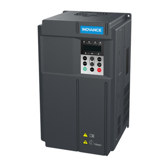
Page 22: Components Of The Md500
1. Product Information MD500 User Manual 1.2 Components of the MD500 MD500 unit. Figure 1-2 Components of the MD500 AC drive with a plastic housing (three-phase 380 to 480 V, 18.5 to 37 kW) Main circuit power indicator Never remove, install or wire the Fan cover drive when the indicator is on. - Page 23 MD500 User Manual 1. Product Information Figure 1-3 Components of the MD500 AC drive with a sheet metal housing (three-phase 380 to 480 V, 45 to 110 kW) Cooling fan For replacement, see section 9.3. Barcode View the serial number and model of the drive here.
- Page 24 1. Product Information MD500 User Manual - 24 - efesotomasyon.com...
- Page 25 Mechanical Installation efesotomasyon.com...
-
Page 26: Mechanical Installation
2. Mechanical Installation MD500 User Manual 2. Mechanical Installation 2.1 Installation Environment Item Requirements Ambient temperature -10°C to 50°C Heat dissipation Clearance” below. Use strong screws or bolts to secure the enclosure on the supporting surface. Mounting location Make sure the mounting location is: Away from direct sunlight Not in an area that has high humidity or condensation Protected against corrosive, combustible or explosive gases and vapours... -
Page 27: Mounting Orientation And Clearance
MD500 User Manual 2. Mechanical Installation 2.2 Mounting Orientation and Clearance Mounting Orientation Always mount the AC drive in an upright position. Mounting Clearance The mechanical clearance requirements for the MD500 vary with power classes of the AC drive. Figure 2-1 Correct mounting clearance of the MD500 Single drive installation Front view Side view... - Page 28 2. Mechanical Installation MD500 User Manual The MD500 series AC drive dissipates heat from the bottom to the top. When multiple AC drives are required to work together, install them side by side. Figure 2-2 Clearance for multi-drive installation Multi-drive installation...
-
Page 29: Physical Appearance And Mounting Dimensions
MD500 User Manual 2. Mechanical Installation 2.3 Physical Appearance and Mounting Dimensions 2.3.1 Physical Appearance Sheet metal housing Plastic housing 2.3.2 Mounting Dimensions Plastic Housing efesotomasyon.com... - Page 30 2. Mechanical Installation MD500 User Manual Sheet Metal Housing d x 4 Table 2-1 Mounting dimensions of the MD500 MD500 Model Dimensions (mm) Weight Three-phase 380 to 480 V MD500T18.5G Ø6 MD500T22G MD500T30G Ø7 MD500T37G MD500T45G Ø10 MD500T55G MD500T75G Ø10 51.5 MD500T110G - 30 -...
-
Page 31: Installation Method And Proces
MD500 User Manual 2. Mechanical Installation 2.4 Installation Method and Proces Installation Method WARNING MD500 units enclosed in a sheet-metal housing have weights of 35 kg or more. These units have eye bolts that Mounting Method Applicable Housing Remark Surface mounting Plastic housing The AC drive is mounted directly on a vertical supporting surface without requiring a rectangular cutout in the surface. - Page 32 2. Mechanical Installation MD500 User Manual See the following two examples. Figure 2-4 Surface-mounted installation of the MD500 plastic housing Figure 2-5 Surface-mounted installation of the MD500 sheet metal housing Eye bolt This completes the mechanical installation of a surface-mounted MD500 housing. You can now follow the instructions in ## to complete removal of the front cover of the MD500 before performing electrical installation.
- Page 33 MD500 User Manual 2. Mechanical Installation 2.4.2 Embedded Mounting There are three stages in the process of preparing an embedded mounting for the MD500 housing: Stage Applicable Housing Remark Stage 1 Fit hanging brackets to the MD500 housing. Stage 2 Prepare the mounting surface by making a cutout and drilling holes as required for the voltage and power rating for your model of MD500.
- Page 34 2. Mechanical Installation MD500 User Manual Figure 2-6 Hanging bracket installation for a plastic housing Installation of the hanging Fit the hanging bracket to the housing and secure bracket is completed. it to the housing by tightening the supplied screws. Continue to see Figure 2-8 Hanging...
- Page 35 MD500 User Manual 2. Mechanical Installation Stage 3: Installing the Housing 10. Lift the housing into the cutout you have prepared. Insert the housing from the correct side of the mounting surface, depending on whether you are using a front-mounting or a rear-mounting arrangement.
-
Page 36: Removing And Installing The
2. Mechanical Installation MD500 User Manual 2.5 Removing and Installing the Front Cover You must remove the front cover before performing electrical installation DANGER Ensure that the drive power-off time exceeds 10 minutes before removing the cover. Be careful when removing the front cover of the AC drive. Falling off of the 2.5.1 Removing and Reattaching the Front Cover of a Plastic Housing Removal Removal is completed. - Page 37 MD500 User Manual 2. Mechanical Installation 2.5.2 Removing and Reattaching the Front Cover of a Sheet Metal Housing Removal Removal is completed. Pinch inwards on the hook found at Hold the lower part of the front cover. either side of the front cover . Lift the front cover.
- Page 38 2. Mechanical Installation MD500 User Manual - 38 - efesotomasyon.com...
- Page 39 Electrical Installation efesotomasyon.com...
-
Page 40: Electrical Installation
3. Electrical Installation MD500 User Manual 3. Electrical Installation 3.1 Typical System Connection For models of to 110 kW For models of 18.5 to 75 kW MDBUN Breaker Contactor Fuse J4 extension port +24V MD38PG5 Forward run (F4-00 = 1) (optional) Reverse run (F4-01 = 2) -
Page 41: Main Circuit Wiring
MD500 User Manual 3. Electrical Installation 3.2 Main Circuit Wiring 3.2.1 Main Circuit Terminals Terminal Arrangement Plastic housing Sheet metal housing POWER MOTOR Terminal Function Table 3-1 Description of input and output connections of MD500 Terminal Name Description R, S, T Three-phase supply input Connections to the three-phase power supply. - Page 42 3. Electrical Installation MD500 User Manual Cable Dimensions and Tightening Torque AC Drive Model Rated Input Current (A) Recommended Cable Tightening Recommended Cable Diameter (mm Torque (N·m) Lug Model MD500T18.5G GTNR10-6 MD500T22G GTNR16-6 161.6 20.2 18.4 20.2 18.4 BR (+) (-) POWER MOTOR AC Drive Model...
- Page 43 MD500 User Manual 3. Electrical Installation 24.8 26.8 POWER MOTOR M8 flat washer combination + spring washer screw + nut AC Drive Model Rated Input Current (A) Recommended Cable Tightening Recommended Cable Diameter (mm Torque (N·m) Lug Model MD500T45G 10.5 GTNR25-8 MD500T55G 10.5...
- Page 44 3. Electrical Installation MD500 User Manual The recommended cable lug is manufactured by Suzhou Yuanli Metal Enterprise. Figure 3-5 Appearance of recommended cable lugs CTNR series TNR series Figure 3-6 Dimensions of recommended TNR series cable lugs Table 3-6 Models and dimensions of the TNR series cable lugs C a b l e L u g Cable Range Current (A)
- Page 45 MD500 User Manual 3. Electrical Installation Figure 3-7 Dimensions of recommended GTNR series cable lugs Table 3-7 Models and dimensions of the GTNR series cable lugs Cable Lug Model Crimping Tool GTNR1.5-5 16.0 RYO-8 GTNR2.5-4 18.0 YYT-8 GTNR2.5-5 20.0 RYO-14 GTNR2.5-6 10.2 GTNR4-5...
- Page 46 3. Electrical Installation MD500 User Manual 3.2.2 Wiring Precautions Cable Selection Inovance recommends symmetrical shielded cable as main circuit cable, which can reduce electromagnetic radiation of the entire conductive system compared with the four-conductor cable. PE conductor and shield Shield...
- Page 47 MD500 User Manual 3. Electrical Installation DC Bus Terminals The DC bus terminals, labeled (+) and (–), are signal terminals that carry a residual voltage for a period after the AC drive has been switched off. To avoid the risk of electric shock, wait for at least 10 minutes after the CHARGE indicator goes off before you touch the equipment.
- Page 48 3. Electrical Installation MD500 User Manual Installation of the cable bracket is as follows: Remove the front cover. Mount the cable bracket to the drive and take three M4*12 screws to fix the Remove the two M4*12 screws bracket at the positions here. from the air inlet plate.
- Page 49 Line Voltage System The MD500 series AC drive is applicable to the line voltage system with neutral point grounded. If it is used in an IT In the scenarios for use with a residual-current circuit breaker (RCCB), if the MCCB opens at startup, remove the EMC...
-
Page 50: Control Circuit Wiring
3. Electrical Installation MD500 User Manual 3.3 Control Circuit Wiring 3.3.1 Control Circuit Terminals Terminal Arrangement Analog input Digital input Pulse input Power and power Relay output +10V GND GND CME COM +24V Pulse output and Analog output Digital common and ground open-collector output and power... - Page 51 MD500 User Manual 3. Electrical Installation Type Terminal Name Description Digital Digital output 1 Optically-coupled isolation, dual-polarity open outputs collector output Output voltage range: 0 to 24 V Output current range: 0 to 50 mA. Note that CME and COM are internally insulated, but are shorted to apply external power to DO1.
- Page 52 3. Electrical Installation MD500 User Manual 3.3.2 Wiring Diagram AI1 Wiring Analog signals at low levels can suffer from the effects of external interference. To reduce this effect, it is important to use shielded cables shorter than 20 m long to carry analog signals. Figure 3-10 Wiring method for use with analog input 1 20 m MD500...
- Page 53 MD500 User Manual 3. Electrical Installation AI2 Wiring Figure 3-12 Wiring method for use with analog input 2 Current flow in direction MD500 Ferrite magnetic core Cross or wind two or three turns in the same direction. DI1-DI5 Wiring (Sink, Source) Where possible, use shielded cables shorter than 20 m long to carry digital on the power supply.
- Page 54 3. Electrical Installation MD500 User Manual In the SINK wiring mode, do not connect the DI terminals of different AC drives in parallel, otherwise a digital input fault will occur. If it is necessary to connect different AC drives in parallel, connect a diode in series at the digital input. The diode characteristics must satisfy the following requirements: Forward current rating If: >10 mA Figure 3-14 Parallel connection of DI terminals in SINK mode...
- Page 55 MD500 User Manual 3. Electrical Installation Wiring of DI5 (High-speed Pulse Input) As high speed pulse input terminal, the DI5 allows maximum frequency input of 100 kHz. MD500 +24V 2.4k Pulse output device DO Wiring When the digital output terminal must drive the relay, it is necessary to install an absorption diode across the relay coil. This diode prevents inductive switching transients causing damage to the DC 24V power supply.
-
Page 56: Wiring Checklist
3. Electrical Installation MD500 User Manual 3.4 Wiring Checklist Item Check the received drive to ensure that you receive a correct model . Make sure the correct peripheral devices (regen resistor, braking Check the optional cards to ensure that the receiving is correct. Check that the mounting method and location meet the requirements. - Page 57 Operations efesotomasyon.com...
-
Page 58: Operations
4. Operations MD500 User Manual 4. Operations 4.1 Introduction to the Operating Panel The operating panel, shown in Figure 4-1, allows you to monitor system operation, modify parameters and start or stop the MD500. Figure 4-1 Details of the operating panel Command source indicator Running direction indicator ON: terminal;... - Page 59 MD500 User Manual 4. Operations Keys on operation panel Key Name Function Enter or exit the Level I menu. Programming Return to the previous menu. Enter each level of the menu interface. ENTER When navigating a menu, it moves the selection up through the screens available. Increment When editing a parameter value, it increases the displayed value.
- Page 60 4. Operations MD500 User Manual Relevant parameters for operation panel setting Function Code Parameter Name Setting Range Default F7-01 MF.K key function selection 0: MF.K key disabled 1: Switchover from remote control (terminal or communication) to keypad control 2: Switchover between forward rotation and reverse rotation 5: Individualized parameter display F7-02 FP-03...
- Page 61 MD500 User Manual 4. Operations Unit Indicators There are three red unit indicators below the data display. These indicators operate individually or in pairs to show the units used to display data, as shown in Figure 4-2. Figure 4-2 Unit indicator explanation Indicator appearance Meaning Hz for frequency...
-
Page 62: Operating Panel Menu Structure
4. Operations MD500 User Manual 4.2 Operating Panel Menu Structure The MD500 operating panel has three levels of menu: 1. Level I - the function parameter group 2. Level II - the function parameter 3. Level III - the function parameter value Figure 4-3 Structure of the three levels of menu F0 28 F0 01... - Page 63 MD500 User Manual 4. Operations The operation procedure of the three levels of menu is as follows: State parameter (default screen) Level I menu ENTER Return Return Level II menu ENTER Return ENTER Level III menu ENTER The following shows how to modify F3-02 from 10.00 Hz to 15.00 Hz. Return ENTER ENTER...
- Page 64 4. Operations MD500 User Manual Press from a Level III menu to: ENTER 1. Save the parameter value you have set 2. Return to the Level II menu, and then 3. Select the next function parameter. Press from a Level III menu to: 1.
-
Page 65: Overall Arrangement Of Function Parameters
MD500 User Manual 4. Operations 4.3 Overall Arrangement of Function Parameters The MD500 includes functions in group F, and new function groups A and U. Function Code Group Description Standard Function Parameters F0 to FP Standard function code group Standard function parameters A0 to AC Advanced function code group U0 to U3... -
Page 66: Function Parameter Operations
4. Operations MD500 User Manual 4.4 Function Parameter Operations 4.4.1 Viewing and Editing Function Parameters Viewing Function Parameters The MD500 provides three display modes for viewing function parameters, described in Table 4-1. Table 4-1 Function parameter display modes Function Code Display Mode Parameter Name Setting Range Base mode... - Page 67 MD500 User Manual 4. Operations Table 14 Setting FP-03 to select the quick-view display modes Value of FP-03 Not displayed Not displayed Not displayed Displayed Displayed Not displayed 11 (default) Displayed Displayed Editing Function Parameters This editing method is mostly used in on-site commissioning. Pressing in Level I menu is to quickly change the function parameter group.
- Page 68 4. Operations MD500 User Manual 4.4.3 Password Security controls this function. When FP-00 has the default value zero, it is not necessary to enter a password to program the MD500. To enable the password protection, do as follows: 2. Make a written note of the value you have set for FP-00 and keep the note in a safe location. 3.
- Page 69 Quick Setup efesotomasyon.com...
-
Page 70: Quick Setup
5. Quick Setup MD500 User Manual 5. Quick Setup 5.1 Get Familiar With Operation Panel panel allows you to monitor system operation, modify parameters and start or stop the MD500. Command source indicator Running direction indicator ON: terminal; ON: reverse; OFF: operation panel;... -
Page 71: Setup Flowchart
MD500 User Manual 5. Quick Setup 5.2 Setup Flowchart START Para. Parameter name Default Commission Before power on Check voltage of power supply Bear in mind that if a higher voltage power supply than necessary is connected to inverter, then inverter will probably get damaged instantly, for example 380V So please check it before power on with a reliable instrument. - Page 72 5. Quick Setup MD500 User Manual CONTINUE Para. Parameter name Default Commission If an encoder is used Set encoder parameters F1-27 Encoder pulses per revolution 1024 1 to 65535ppr F1-28 Encoder type 0: ABZ incremental encoder 1: UVW incremental encoder 2: Resolver 4: Wire-saving UVW encoder F1-30...
- Page 73 MD500 User Manual 5. Quick Setup CONTINUE Para. Parameter name Default Commission Select frequency reference source F0-03 Main frequency source X selection 0:Digital setting F0-08 (pressing can revise F0-08 easily, and the revised value won’t be cleared even after power off) 1:Digital setting F0-08 (pressing can change F0-08 easily, but the revised value would be cleared after power off)
- Page 74 5. Quick Setup MD500 User Manual CONTINUE Para. Parameter name Default Commission If AI3 is frequency reference Set AI3 F4-23 AI curve 3 minimum input 0.00 0 V to F4-25; F4-24 Corresponding setting of AI3 minimum input 0.0 -100.0% to 100.0% F4-25 AI3 maximum input 10.00...
- Page 75 MD500 User Manual 5. Quick Setup CONTINUE Para. Parameter name Default Commissioning If any digital input is used Set DI function F4-00 DI1 function selection F4-01 0: No function 1: Forward RUN (FWD) 2: Reverse RUN (REV) 3: Three-wire control 4: Forward JOG (FJOG) 5: Reverse JOG (RJOG) 6: Terminal UP...
- Page 76 5. Quick Setup MD500 User Manual CONTINUE Para. Parameter name Default Commission F4-00 DI1 function selection 33: External fault normally closed (NC) input 35: PID action direction reverse 36: External STOP terminal 1 37: Command source switchover terminal 2 38: PID integral disabled 40: Switchover between auxiliary frequency source Y and preset frequency 41: Motor selection terminal 1 42: Motor selection terminal 2...
- Page 77 MD500 User Manual 5. Quick Setup CONTINUE Para. Parameter name Default Commissioning If any digital output is used Set DO function F5-00 FM output mode selection 0: FM terminal outputs pulses, the frequency of which represents the value of variable which is assigned by F5-06. 1: FM terminal outputs switch signal, the value of which represents the status of variable which is assigned by F5-01 F5-01...
- Page 78 5. Quick Setup MD500 User Manual CONTINUE Para. Parameter name Default Commissioning If any digital output is used Set DO function F5-01 FM (switch signal) function selection 26: Frequency 1 reached 27: Frequency 2 reached 28: Current 1 reached 30: Timing duration reached 31: AI1 input limit exceeded 32: Load lost 33: Reverse running...
- Page 79 MD500 User Manual 5. Quick Setup CONTINUE Para. Parameter name Default Commissioning F5-04 DO1 function selection Setting range same as FM F5-05 Extension card DO2 function selection Setting range same as FM F5-06 FM (pulse signal) function selection 0: Running frequency 1: Set frequency 2: Output current 3: Output torque (absolute value)
- Page 80 5. Quick Setup MD500 User Manual CONTINUE Para. Parameter name Default Commissioning if it is VF control Set VF parameters F3-00 SETTING RANGE: 0 to 11; F3-01 Torque boost 0.0 to 30.0 %; NOTE: if it is 0, then auto torque boost is activated, and it is recommended to use auto torque boost.
- Page 81 MD500 User Manual 5. Quick Setup CONTINUE Para. Parameter name Default Commissioning if it is SVC or FVC control F2-00 Speed loop proportional gain 1 To achieve better performance 0 to 100. F2-01 Speed loop integral time 1 0.01 to 10.00 Sec. F2-02 Switchover frequency 1 5.00...
- Page 82 5. Quick Setup MD500 User Manual - 82 - efesotomasyon.com...
- Page 83 MD500 User Manual 6. Parameter Table Parameter Table - 83 - efesotomasyon.com...
-
Page 84: Parameter Table
6. Parameter Table MD500 User Manual 6. Parameter Table 6.1 Introduction Note Password protection is available for use with the MD310 AC Drive. If this protection has been enabled, you See section 4.4.3 "Password Security" for instructions to set and remove password protection. Groups F and A include standard function parameters. -
Page 85: Standard Parameters
MD500 User Manual 6. Parameter Table 6.2 Standard Parameters Parameter No. Parameter Name Setting Range Default Property Group F0: Standard Parameters F0-00 1 and 2 Model dependent F0-01 Motor 1 control mode 0 to 2 F0-02 Command source selection 0 to 2 F0-03 Main frequency reference setting channel selection... - Page 86 6. Parameter Table MD500 User Manual Function Code Parameter Name Setting Range Default Property F0-23 Retentive of digital setting 0, 1 frequency upon stop F0-24 Motor parameter group selection 0: Motor parameter group 1 1: Motor parameter group 2 F0-25 0 to 2 time base frequency F0-26...
- Page 87 MD500 User Manual 6. Parameter Table Function Code Parameter Name Setting Range Default Property F2-02 Switchover frequency 1 0.00 to F2-05 5.00 Hz F2-03 Speed loop proportional gain 2 1 to 100 F2-04 Speed loop integral time 2 0.01s to 10.00s 1.00s F2-05 Switchover frequency 2...
- Page 88 6. Parameter Table MD500 User Manual Function Code Parameter Name Setting Range Default Property F3-14 Digital setting of voltage 0 V to rated motor voltage F3-15 0.0s to 1000.0s 0.0s F3-16 Voltage decline time 0.0s to 1000.0s 0.0s F3-17 Stop mode selection 0: Frequency and voltage declining to 0 independently 1: Frequency declining after voltage declines to 0...
- Page 89 MD500 User Manual 6. Parameter Table Function Code Parameter Name Setting Range Default Property F4-23 AI3 curve min. input -10.00 V to F4-25 0.00 V F4-24 Corresponding percentage -100.00% to 100.0% 0.0% of AI3 curve min. input F4-25 AI3 curve max. input F4-23 to 10.00 V 10.00 V F4-26...
- Page 90 6. Parameter Table MD500 User Manual Function Code Parameter Name Setting Range Default Property F6-00 Startup mode 0: Direct start 1: Catching a spinning motor 2: Pre-excited start F6-01 Mode of catching a 0: From stop frequency spinning motor 1: From zero speed 2: From max.
- Page 91 MD500 User Manual 6. Parameter Table Function Code Parameter Name Setting Range Default Property Group F8: Auxiliary Functions F8-00 Jog running frequency reference 0.00 Hz to maximum frequency 2.00 Hz F8-01 Jog acceleration time 0.0s to 6500.0s 20.0s F8-02 Jog deceleration time 0.0s to 6500.0s 20.0s F8-03...
- Page 92 6. Parameter Table MD500 User Manual Function Code Parameter Name Setting Range Default Property F8-37 Output overcurrent 0.00s to 600.00s 0.00s detection delay F8-38 Detection of current 1 0.0% to 300.0% (rated motor current) 100.0% Detection width of current 1 0.0% to 300.0% (rated motor current) 0.0% F8-40...
- Page 93 MD500 User Manual 6. Parameter Table Function Code Parameter Name Setting Range Default Property AC drive state upon 3rd fault Current power-on time upon 3rd fault Current running time upon 3rd fault Frequency upon 2nd fault Current upon 2nd fault Bus voltage upon 2nd fault DI state upon 2nd fault Digital output terminal...
- Page 94 6. Parameter Table MD500 User Manual Function Code Parameter Name Setting Range Default Property Load lost detection level 0.0% to 100.0% (rated motor current) 10.0% Load lost detection time 0.0s to 60.0s 1.0s Overspeed detection level 0.0% to 50.0% (max. frequency) 20.0% Overspeed detection time 0.0s to 60.0s...
- Page 95 MD500 User Manual 6. Parameter Table Function Code Parameter Name Setting Range Default Property Fb-02 Wobble step 0.0% to 50.0% 0.0% Fb-03 Wobble cycle 0.0s to 3000.0s 10.0s Fb-04 Triangular wave rising 0.0% to 100.0% 50.0% Fb-05 Set length 0 to 65535 m 1000 m Fb-06 Actual length...
- Page 96 6. Parameter Table MD500 User Manual Function Code Parameter Name Setting Range Default Property 0 to 3 of simple PLC reference 5 FC-30 Running time of simple 0.0s (h) to 6553.5s (h) 0.0s (h) PLC reference 6 FC-31 0 to 3 of simple PLC reference 6 FC-32 Running time of simple...
- Page 97 MD500 User Manual 6. Parameter Table Function Code Parameter Name Setting Range Default Property Fd-06 Current resolution read 0: 0.01 by communication 1: 0.1 Fd-08 CANlink communication 0.0 (Invalid) timeout time 0.1 to 60.0 FE-00 F0-00 to FP-xx, A0-00 to Ax-xx, U0- F0-00 00 to U0-xx, U3-00 to U3-xx FE-01...
- Page 98 6. Parameter Table MD500 User Manual Function Code Parameter Name Setting Range Default Property FP-04 Selection of parameter 0, 1 Group A0: Torque Control and Limit A0-00 0, 1 A0-01 Torque reference source 0 to 7 in torque control A0-03 Torque digital setting -200.0% to 200.0% 150.0%...
- Page 99 MD500 User Manual 6. Parameter Table Function Code Parameter Name Setting Range Default Property A2-04 Rated motor frequency 0.01 Hz to max. frequency Model dependent 1 to 65535 rpm Model A2-05 Rated motor speed dependent A2-06 Stator resistance Auto-tuning dependent A2-07 Rotor resistance Auto-tuning...
- Page 100 6. Parameter Table MD500 User Manual Function Code Parameter Name Setting Range Default Property A2-63 Motor 2 torque boost Model dependent 0.1% to 30.0% A2-65 Motor 2 oscillation 0 to 100 Model suppression gain dependent Group A5: Control Optimization A5-00 DPWM switchover 5.00 Hz to max.
- Page 101 MD500 User Manual 6. Parameter Table Function Code Parameter Name Setting Range Default Property Jump amplitude of AI3 input 0.0% to 100.0% 0.5% corresponding setting Group A7: User Programmable Card A7-00 User programmable 0: Disabled function selection 1: Enabled A7-01 AC drive output terminal 00000 to 11111 00000...
- Page 102 6. Parameter Table MD500 User Manual Function Code Parameter Name Setting Range Default Property AC-03 AI1 displayed voltage 2 Factory- corrected AC-04 AI2 measured voltage 1 0.500 to 4.000 V Factory- corrected AC-05 AI2 displayed voltage 1 0.500 to 4.000 V Factory- corrected AC-06...
-
Page 103: Monitoring Function Codes
MD500 User Manual 6. Parameter Table 6.3 Monitoring Function Codes Function Code Parameter Name Display Range Group U0: Monitoring Parameters U0-00 Running frequency 0.00 to 500.00 Hz U0-01 Frequency reference 0.00 to 500.0 Hz U0-02 Bus voltage 0.0 to 3000.0 V U0-03 Output voltage 0 to 1140 V... - Page 104 6. Parameter Table MD500 User Manual Function Code Parameter Name Display Range U0-62 Current fault code U0-63 Sending value of point-point communication -100.00% to 100.00% U0-64 Number of slaves 0 to 63 U0-65 Torque upper limit -200.00% to 200.00% U0-66 Communication extension card type 100: CANopen 200: PROFIBUS-DP...
- Page 105 Description of Parameters efesotomasyon.com...
-
Page 106: Description Of Parameters
7. Description of Parameters MD500 User Manual 7 Description of Parameters The MD500 AC drive has the following three control methods to start and to stop the MD500 AC drive. Operating panel keys Terminal control Communication control You can select the proper control mode in function parameter F0-02. Function Code Parameter Name Setting Range... - Page 107 MD500 User Manual 7. Description of Parameters 7.1.1 Terminal Control Function Code Parameter Name Setting Range Default F4-11 Terminal command mode 0: Two-wire control mode 1 1: Two-wire control mode 2 2: Three-wire control mode 1 3: Three-wire control mode 2 Figure 7-1 Four terminal control modes F0-02 Command source selection...
- Page 108 7. Description of Parameters MD500 User Manual The following example takes DI1, DI2 and DI3 to describe how to control the AC drive via DI terminals. F4-11 = 0: Two-wire Control Mode 1 It is the most commonly used two-wire control mode. Allocate the DI1 with the forward run function and the DI2 with the reverse run function.
- Page 109 MD500 User Manual 7. Description of Parameters Figure 7-3 Timing diagram of the two-wire control mode 1 on normal condition SW1 forward run command SW2 reverse run command Motor speed Motor rotating in Motor rotating in Stop forward direction reverse direction Figure 7-4 Timing diagram of the two-wire control mode 1 on abnormal condition SW1 forward run command...
- Page 110 7. Description of Parameters MD500 User Manual F4-11 = 1: Two-wire Control Mode 2 In this mode, DI1 is RUN enabled terminal, and DI2 determines the running direction. Allocate the DI1 with the run enabled function and the DI2 with the running direction. The parameters are set as below: Function Code Parameter Name...
- Page 111 MD500 User Manual 7. Description of Parameters F4-11 = 2: Three-wire Control Mode 1 In this mode, DI3 is the three-wire control terminal. The DI1 is allocated with the forward run function and the DI2 is allocated with the reverse run function. The parameters are set as below: Function Code Parameter Name Value...
- Page 112 7. Description of Parameters MD500 User Manual F4-11 = 3: Three-wire Control Mode 2 In this mode, DI3 is the three-wire control command terminal. DI1 determines whether the run command is enabled and DI2 determines the running direction. The parameters are set as below: Function Code Parameter Name Value...
- Page 113 MD500 User Manual 7. Description of Parameters 7.1.2 Communication Control as Modbus, PROFIBUS-DP, CANlink, or CANopen. To use communication with the MD500, the matching communication card must be installed. If the communication protocol is Modbus, PROFIBUS-DP or CANopen, select the proper serial communication protocol in F0-28. The CANlink protocol is always valid.
-
Page 114: Frequency Reference Settings
7. Description of Parameters MD500 User Manual 7.2 Frequency Reference Settings Main frequency reference Auxiliary frequency reference Main & auxiliary superposition Binding command source to main frequency reference 7.2.1 Setting the Main Frequency Reference The main frequency reference has nine setting modes. 2. - Page 115 MD500 User Manual 7. Description of Parameters Figure 7-12 select a proper channel to set the main frequency reference Operation panel Digital setting Non-retentive F0-08 Digital setting Retentive Analog inputs Main 0 to 10 V frequency reference 0 to 10 V F4-33 (Select AI curve) 4 to 20 mA...
- Page 116 7. Description of Parameters MD500 User Manual Digital Setting (Non-retentive at Power Down) The initial value of the frequency reference is F0-08 (Preset frequency). You can change the frequency reference by pressing When the MD500 is powered on again after power down, the frequency reference continues from the value of F0-08. Digital Setting (Retentive at Power Down) The initial value of the frequency reference is F0-08 (Preset frequency).
- Page 117 MD500 User Manual 7. Description of Parameters Analog Input 2. AI1 (0 to 10 V voltage input) 4. AI3 (-10 to 10 V voltage input) The frequency reference is entered from an analog input (AI) terminal. To input the frequency reference from an AI terminal, do as follows: Steps Related Parameters...
- Page 118 7. Description of Parameters MD500 User Manual When the analog input voltage exceeds the value of F4-15, the AC drive uses the maximum value. When the analog input voltage is below the value of F4-13, the AC drive uses the minimum value or 0.0%, determined by the setting of F4-34.
- Page 119 MD500 User Manual 7. Description of Parameters curve 3 are linear correspondence and AI curve 4 and AI curve 5 are four-point correspondence. Figure 7-15 Diagram of curve 4 and curve 5 AI corresponding 100% percentage Corresponding percebtage of AI max. input Corresponding percentage of AI curve inflexion 1 input...
- Page 120 7. Description of Parameters MD500 User Manual Step 2: Select a proper curve for the AI terminal. group F4. Curve 4 and curve 5 are 4-point curves, set in group A6. Function Code Parameter Name Setting Range Default F4-33 AI curve selection Curve 1 (2 points, see F4-13 to F4-16) Curve 2 (2 points, see F4-18 to F4-21) Curve 3 (2 points, see F4-23 to F4-26)
- Page 121 MD500 User Manual 7. Description of Parameters Example 2: On the condition that the analog input from AI2 is current, if the input is 0 to 20 mA, it corresponds to voltage input of 0 to 10 V. If the input is 4 to 20 mA, it corresponds to 2 to 10 V. To make the current input at AI2 to control the frequency reference and correspond 4 to 20 mA to 0 to 50 Hz, the settings are shown Figure 7-17 Current input at AI2 to control the frequency reference Corresponding...
- Page 122 7. Description of Parameters MD500 User Manual Pulse Reference (DI5) (voltage range) and 0 to 100 kHz (frequency range). The corresponding value 100% of the pulse reference corresponds to the value of F0-10 (Max. frequency). Note The main frequency reference set via pulse reference and the pulse output of the FM terminal (F5-00 = 1) cannot be used simultaneously.
- Page 123 MD500 User Manual 7. Description of Parameters Multi-reference continuously, and where only several frequencies are required. The multi-reference is a relative value and is a percentage of F0-10 (max. frequency). Whether the setting is positive or negative determines the drive running direction. If negative, it indicates that the AC drive runs in the reverse direction. The multiple references are set in group FC, as listed in the following table.
- Page 124 7. Description of Parameters MD500 User Manual Here uses DI2, DI4, DI7 and DI8 for setting the multi-reference function. The diagram and related parameter setting of the multi- Figure 7-20 Using multi-reference to control the frequency reference 16 frequency (Binary) references (%) State combination FC-00...
- Page 125 MD500 User Manual 7. Description of Parameters Simple PLC When using the simple PLC mode as the frequency reference setting channel, the MD500 running frequency can be switched among the 16 frequency references. Figure 7-21 Using the simple PLC mode to control the frequency reference Running FC-14 direction...
- Page 126 7. Description of Parameters MD500 User Manual Function Code Parameter Name Setting Range Default FC-33 0 to 3 of simple PLC reference 7 FC-34 Running time of simple 0.0s (h) to 6553.5s (h) 0.0s (h) PLC reference 8 FC-35 0 to 3 of simple PLC reference 8 FC-36 Running time of simple...
- Page 127 MD500 User Manual 7. Description of Parameters FC-16 determines the simple PLC running mode. Function Code Parameter Name Setting Range Default FC-16 Simple PLC running mode 0: Stop after running one cycle 2: Repeat after running one cycle FC-16 = 0: Stop after running one cycle The AC drive stops after running one cycle, and will not start up until receiving new RUN command.
- Page 128 7. Description of Parameters MD500 User Manual PID Reference pressure, temperature, and so on. The purpose of the PID control is to keep the drive output frequency as close as possible to a desired reference via the PID Proportional gain (Kp1) A large value tends to reduce the present error, but too large setting will cause system oscillation.
- Page 129 MD500 User Manual 7. Description of Parameters Figure 7-23 Function block diagram of the PID control FA-00 PID reference setting channel FA-1 FA-03 PID 1 FA-05: P gain 1 PID operation direction PID limit Pulse reference FA-06: I time 1 0: Forward operation F0-10 in forward direction FA-07: D time 1...
- Page 130 7. Description of Parameters MD500 User Manual Function Code Parameter Name Setting Range Default FA-03 PID operation direction 0: Forward operation 1: Reverse operation FA-04 PID reference and 0 to 65535 1000 feedback range FA-05 Proportional gain Kp1 0.0 to 100.0 20.0 FA-06 Integral time Ti1...
- Page 131 MD500 User Manual 7. Description of Parameters Function Code Parameter Name Setting Range Default FA-15 Proportional gain Kp2 0.0 to 100.0 20.0 FA-16 Integral time Ti2 0.01s to 10.00s 2.00s FA-17 Differential time Td2 0.000s to 10.000s 0.000s FA-18 PID parameter switchover 0: No switchover condition 1: Switchover via DI...
- Page 132 7. Description of Parameters MD500 User Manual Function Code Parameter Name Setting Range Default FA-23 Max. deviation between two PID 0.00% to 100.00% 1.00% outputs in forward direction FA-24 Max. deviation between two PID 0.00% to 100.00% 1.00% outputs in reverse direction FA-23 and FA-24: These function parameters limit the deviation between two PID outputs (2 ms per PID output) to suppress rapid change of PID output and stabilize the drive running.
- Page 133 MD500 User Manual 7. Description of Parameters Communication Reference as Modbus, PROFIBUS-DP, CANlink, or CANopen. To use communication with the MD500, the matching communication card must be installed. If the communication protocol is Modbus, PROFIBUS-DP or CANopen, select the proper serial communication protocol in F0-28. The CANlink protocol is always valid.
- Page 134 7. Description of Parameters MD500 User Manual 7.2.2 Setting the Auxiliary Frequency Reference The auxiliary frequency reference has the same nine setting modes as the main frequency reference does. F0-04 selects a proper channel to set the auxiliary frequency reference. Function Code Parameter Name Setting Range...
- Page 135 MD500 User Manual 7. Description of Parameters 7.2.3 Main & Auxiliary Superposition reference in F0-07. and between auxiliary or main & auxiliary superposition. F0-08 Digital input (non-retentive) F0-03 Digital input (retentive) F0-08 Analog input Fx-xx Pulse input Fx-xx Main frequency reference Main Multi- frequency input Fx-xx...
- Page 136 7. Description of Parameters MD500 User Manual Function Code Parameter Name Setting Range Default F0-07 Final frequency reference Unit's digit: Frequency reference selection setting selection 0: Main frequency reference 1: Main and auxiliary superposition (superposition relationship determined by ten's digit) 2: Switchover between main and auxiliary 3: Switchover between main and "main &...
- Page 137 MD500 User Manual 7. Description of Parameters 7.2.4 Binding Command Source to Frequency Reference Setting Channel It is possible to bind the three command sources separately to any of the frequency reference setting channel. Operating panel Unit's Unit's digit Ten's Main Hundred's Auxiliary...
- Page 138 7. Description of Parameters MD500 User Manual 7.2.5 Frequency Reference Limit Function Code Parameter Name Setting Range Default F0-10 Max. frequency 50.00 to 500.00 Hz 50.00 Hz F0-11 Setting channel of frequency 0: Set by F0-12 reference upper limit 1: AI1 2: AI2 3: AI3 4: Pulse reference (DI5)
-
Page 139: Start/Stop The Ac Drive
MD500 User Manual 7. Description of Parameters 7.3.1 Start Mode You can set the start mode of the AC drive in F6-00, direct start, catching a spinning motor and pre-excited start. The related function parameters are listed as follows: Function Code Parameter Name Setting Range Default... - Page 140 7. Description of Parameters MD500 User Manual Figure 7-30 (2) Timing diagram of start with start frequency Output frequency F6-03 (start frequency) Start command Acceleration time F6-04 (Start frequency holding time) Output frequency Start command Acceleration time command F6-06 1 active time) F6-00 = 1: Catching a spinning motor To catch a spinning motor, the AC drive detects the speed and direction of the spinning motor, and then starts to run from the spinning motor frequency, minimizing impact of power supply to the motor.
- Page 141 MD500 User Manual 7. Description of Parameters 6.3.2 Stop Mode You can set the stop mode of the AC drive in F6-10, decelerate to stop and coast to stop. The related function parameters are listed as follows: Function Code Parameter Name Setting Range Default F6-10...
- Page 142 7. Description of Parameters MD500 User Manual F6-10 = 0: Decelerate to stop Once the stop command is input, the AC drive decreases the output frequency based on the deceleration time to 0. Figure 7-33 Decelerate to stop Output frequency Start command Acceleration time Deceleration time...
- Page 143 MD500 User Manual 7. Description of Parameters frequency (F0-25). (F0-25) to 0 Hz. Output frequency (Hz) Accel decel. time base frequency Frequency reference Time (t) Actual decel. time Actual accel. time Set accel. time Set decel. time terminal. Group 1: F0-17, F0-18 Group 2: F8-03, F8-04 Group 3: F8-05, F8-06 Group 4: F8-07, F8-08...
- Page 144 7. Description of Parameters MD500 User Manual Function Code Parameter Name Setting Range Default F0-17 Acceleration time 1 Model dependent F0-18 Deceleration time 1 Model dependent F8-03 Acceleration time 2 0.0s to 6500.0s Model dependent F8-04 Deceleration time 2 0.0s to 6500.0s Model dependent F8-05...
-
Page 145: Motor Auto-Tuning
MD500 User Manual 7. Description of Parameters 7.4 Motor Auto-tuning You can obtain the parameters of the controlled motor through motor auto-tuning. The motor auto-tuning methods are static auto-tuning 1, static auto-tuning 2 and dynamic auto-tuning. You can select a proper auto-tuning method in F1-37. - Page 146 7. Description of Parameters MD500 User Manual F1-37 = 2: Dynamic auto-tuning If the motor has the constant output characteristic and is used for high-accuracy application, disconnect the motor from the load and use the dynamic auto-tuning. It is applicable to the SVC or CLVC mode. The dynamic auto-tuning process is as follows: Steps Description...
- Page 147 MD500 User Manual 7. Description of Parameters The related parameters are described as follows: Function Code Parameter Name Setting Range Default F1-00 Motor type selection 0: Common asynchronous motor 1: Variable frequency asynchronous motor F1-01 Rated motor power 0.1 to 1000.0 kW Model dependent F1-02...
- Page 148 7. Description of Parameters MD500 User Manual Function Code Parameter Name Setting Range Default F1-28 Encoder type 0: ABZ incremental encoder 2: Resolver F1-28: Different types of encoders require different PG cards. Set this function parameter correctly after installation of a proper PG card is completed.
-
Page 149: Control Performance
MD500 User Manual 7. Description of Parameters 7.5 Control Performance Function Code Parameter Name Setting Range Default F3-00 F3-01 Torque boost Model dependent 0.1% to 30% F3-02 Cut-off frequency of torque boost 0.00 Hz to max. frequency 50.00 Hz F3-03 0.00 Hz to F3-05 0.00 Hz F3-04... - Page 150 7. Description of Parameters MD500 User Manual Output voltage Rated voltage F3-08: V3 F3-06: V2 Rated frequency F3-04: V1 Output frequency F3-03 F3-05 F3-07 F3-03. Output voltage F1-02 (Rated voltage) F1-04 (Rated frequency) F3-01 (Torque boost) Output frequency The output voltage and the output frequency change according to the square curve when below the rated frequency. It is applicable to light-load application where the load does change usually, such as fan and water pump.
- Page 151 MD500 User Manual 7. Description of Parameters Function Code Parameter Name Setting Range Default F3-13 0: Set by F3-14 1: AI1 2: AI2 3: AI3 4: Pulse reference (DI5) 5: Multi-reference 6: Simple PLC 7: PID 8: Communication reference 100.0% corresponds to the rated motor voltage (F1-02, A2-02). F3-14 Digital setting of voltage 0 V to rated motor voltage...
- Page 152 7. Description of Parameters MD500 User Manual 7.5.2 Torque Boost and Slip Compensation Torque Boost Function Code Parameter Name Setting Range Default F3-01 Torque boost Model dependent 0.1% to 30% F3-02 Cut-off frequency of torque boost 0.00 Hz to max. frequency 50.00 Hz in motor overheat and AC drive overcurrent.
- Page 153 MD500 User Manual 7. Description of Parameters Slip Compensation The slip compensation function compensates for the motor speed slip when load increases. Function Code Parameter Name Setting Range Default F1-05 Rated motor speed 1 to 65535 RPM Model dependent 0% to 200.0% 0.0% is obtained from calculation of the rated motor frequency and rated motor speed.
- Page 154 7. Description of Parameters MD500 User Manual Function Code Parameter Name Setting Range Default F3-18 Overcurrent stall prevention level 50% to 200% 150% Overcurrent stall 0: Disabled prevention selection 1: Enabled F3-20 Overcurrent stall prevention gain 0 to 100 F3-21 Speed multiplying overcurrent 50% to 200% stall prevention level...
- Page 155 MD500 User Manual 7. Description of Parameters 7.5.4 Overvoltage Stall Prevention and Braking Unit Action Voltage When the bus voltage exceeds the value set F3-22, it indicates that the motor becomes an electric generator (motor speed larger (dissipates the regenerative energy). Using this function will increase the deceleration time and avoid overvoltage trip.
- Page 156 7. Description of Parameters MD500 User Manual 7.5.5 Speed Loop Function Code Parameter Name Setting Range Default F2-00 Speed loop proportional gain 1 0 to 100 F2-01 Speed loop integral time 1 0.01 to 10.00s 0.50s F2-02 Switchover frequency 1 0.00 to F2-05 5.00 Hz F2-03...
- Page 157 MD500 User Manual 7. Description of Parameters 7.5.6 Vector Control Slip Compensation Gain Function Code Parameter Name Setting Range Default F2-06 Vector control slip 50% to 200% 100% compensation gain 7.5.7 SVC Speed Feedback Stability Function Code Parameter Name Setting Range Default F2-07 0.000s to 1.000s...
- Page 158 7. Description of Parameters MD500 User Manual Setting Torque Limit in Speed Control Function Code Parameter Name Setting Range Default Torque limit source in 0: F2-10 speed control (motoring) 1: AI1 2: AI2 3: AI3 4: Pulse reference (DI5) 5: Communication reference 6: Min.
- Page 159 MD500 User Manual 7. Description of Parameters Setting Torque Limit in Torque Control Function Code Parameter Name Setting Range Default A0-01 Torque reference source 0: Set by A0-03 in torque control 1: AI1 2: AI2 3: AI3 4: Pulse reference (DI5) 5: Communication reference 6: MIN (AI1, AI2) 7: MAX (AI1, AI2)
- Page 160 7. Description of Parameters MD500 User Manual Function Code Parameter Name Setting Range Default F2-13 0 to 60000 2000 proportional gain F2-14 0 to 60000 1300 integral gain F2-15 0 to 60000 2000 proportional gain F2-16 0 to 60000 1300 These function parameters are vector control current loop PI parameters.
-
Page 161: Protections
MD500 User Manual 7. Description of Parameters 7.6 Protections This section introduces the functions on protecting the AC drive and the motor. 7.6.1 Motor Overload Protection Function Code Parameter Name Setting Range Default Motor overload 0: Disabled protection selection 1: Enabled Motor overload protection gain 0.20 to 10.00 1.00... - Page 162 7. Description of Parameters MD500 User Manual For example, the application requires report of Err11 when the motor runs at 150% of rated motor current for two minutes. According to Figure 7-47, 150% (I) is in the range of 145% (I1) and 155% (I2). 145% corresponds to the overload protection time 6 minutes (T1) and 145% corresponds to the overload protection time 4 minutes (T2).
- Page 163 MD500 User Manual 7. Description of Parameters 7.6.3 Fault Reset Function Code Parameter Name Setting Range Default Auto reset times 0 to 20 This function parameter sets the allowable times of auto fault reset. If the reset times exceed the value set in this parameter, the AC drive will keep the fault state.
- Page 164 7. Description of Parameters MD500 User Manual Function Code Parameter Name Setting Range Default Fault protection action 00000 selection 3 Thousand’s digit: Load lost (Err30) 0: Coast to stop 1: Stop according to the stop mode 2: Continue to run at 7% of rated motor frequency and restore to the frequency reference if the load recovers Ten thousand's digit: PID feedback lost during drive running (Err31)
- Page 165 MD500 User Manual 7. Description of Parameters 7.6.5 Motor Overheat Protection Function Code Parameter Name Setting Range Default Type of motor temperature sensor 0: No temperature sensor 1: PT100 2: PT1000 Motor overheat 0°C to 200°C 110°C protection threshold Motor overheat pending threshold 0°C to 200°C motor overheat protection.
- Page 166 7. Description of Parameters MD500 User Manual Function Code Parameter Name Setting Range Default Power dip ride-through 0: Disabled function selection 1: Bus voltage constant control 2: Decelerate to stop Voltage level of power dip ride- 85% to 120% through function disabled Judging time of bus voltage 0.1s to 10.0s 0.5s...
- Page 167 MD500 User Manual 7. Description of Parameters 7.6.8 Overspeed Protection Function Code Parameter Name Setting Range Default Overspeed detection level 0.0% to 50.0% (max. frequency) 20.0% Overspeed detection time 0.0s to 60.0s 1.0s sensor. Function Code Parameter Name Setting Range Default Detection level of too large 0.0% to 50.0% (max.
-
Page 168: Monitoring
7. Description of Parameters MD500 User Manual 7.7 Monitoring The monitoring function enables you to view the AC drive state in the LED display area on the operation panel. You can monitor the AC drive state in the following two ways: 1. - Page 169 MD500 User Manual 7. Description of Parameters Function Code Parameter Name Setting Range Default F7-03 LED display running 0000 to FFFF parameters 1 Running frequency 1 (Hz) Frequency reference (Hz) Bus voltage (V) Output voltage (V) Output current (A) Output power (kW) Output torque (%) DI state (V) DO state...
- Page 170 7. Description of Parameters MD500 User Manual Function Code Parameter Name Setting Range Default F7-05 LED display stop parameters 0000 to FFFF Frequency reference (Hz) Bus voltage (V) DI state DO state AI1 voltage (V) AI2 voltage (V) AI3 voltage (V) Count value Length value PLC stage...
- Page 171 MD500 User Manual 7. Description of Parameters View Parameters in Group U0 You can view the parameter values by using operation panel, convenient for on-site commissioning, or from the host computer by means of communication (address: 0x7000-0x7044). Function Code Parameter Name Display Range Group U0: Monitoring Parameters U0-00...
- Page 172 7. Description of Parameters MD500 User Manual Function Code Parameter Name Display Range Feedback speed -320.00 to 320.00 Hz -500.0 to 500.0 Hz If the ten's digit is set to 2, the display range is -320.00 to 320.00 Hz. If the ten's digit is set to 1, the display range is -500.0 to 500.0 Hz. Function Code Parameter Name Display Range...
- Page 173 MD500 User Manual 7. Description of Parameters Function Code Parameter Name Display Range U0-30 Main frequency X 0.00 to 500.00 Hz U0-31 Auxiliary frequency Y 0.00 to 500.00 Hz U0-34 Motor temperature 0°C to 200°C U0-35 Target torque -200.0% to 200.0% U0-36 Resolver position U0-37...
- Page 174 7. Description of Parameters MD500 User Manual Function Code Parameter Name Display Range U0-44 DI set for function state display 2 Function Code Parameter Name Display Range U0-58 Phase Z counting 0 to 65535 U0-58: It displays the phase Z counting of the current ABZ or UVW encoder. The value increases or decreases by 1 every time the encoder rotates one revolution forwardly or reversely.
-
Page 175: Process
MD500 User Manual 7. Description of Parameters 7.8 Process This section introduces the three commonly used process functions, the wobble function, the fixed length control and the counting function. 7.8.1 The Wobble Function It indicates the output frequency wobbles up and down with the frequency reference as the center. Set wobble function related parameters. - Page 176 7. Description of Parameters MD500 User Manual The related function parameters are as follows: Function Code Parameter Name Setting Range Default Fb-00 Wobble setting mode 0: Relative to the frequency reference 1: Relative to the max. frequency This function parameter selects the base value of the wobble amplitude. Function Code Parameter Name Setting Range...
- Page 177 MD500 User Manual 7. Description of Parameters Any of F5-00 Allocate DO with the to F5-05 = 10 length reached function. Fb-05 Allocate DI5 with the length signal F4-04 = 27 Set length pulses counting function. DO outputs the length Compare reached signal.
- Page 178 7. Description of Parameters MD500 User Manual 7.8.3 The Counting Function The MD500 has the counting function. The sampling DI terminal must be set for the function 25 "Counter input ". For high pulse frequency, use terminal DI5. Function Code Parameter Name Setting Range Default...
- Page 179 MD500 User Manual 7. Description of Parameters 7.8.4 Motor 2 Parameters The MD500 supports driving two motors at different time. For the two motors, you can: Set motor nameplate parameters respectively Perform motor auto-tuning respectively Set encoder-related parameters respectively You can select the desired motor parameter group in F0-24 or via a DI terminal 1.
- Page 180 7. Description of Parameters MD500 User Manual Function Code Parameter Name Setting Range Default A2-10 No-load current Auto-tuning parameter 0.1 to F1-03 (AC drive power > 55 kW) A2-27 Encoder pulses per revolution 1 to 65535 1024 A2-28 Encoder type 0 to 2 Speed feedback PG selection 0 to 2...
- Page 181 MD500 User Manual 7. Description of Parameters Figure 7-54 The user programmable use schematic (2) Control mode AC drive control Unit's digit of A7-01 (See details in group PLC program modified (FM used as digital PLC controls PLC program 0: output invalid output) digital output control...
- Page 182 7. Description of Parameters MD500 User Manual 1. Set whether the user programmable card is valid. Function Code Parameter Name Setting Range Default A7-00 User programmable 0: Disabled function selection 1: Enabled 2. Set the AI3 and AO2 function on the user programmable card. Function Code Parameter Name Setting Range...
- Page 183 MD500 User Manual 7. Description of Parameters 4. Set the running command When F0-02 = 2 (the command source is communication) and A7-00 = 1 (the user programmable card is enabled), the drive running is controlled by the setting of A7-08. You can implement control of the AC drive via the PLC program by operating the corresponding D component.
- Page 184 7. Description of Parameters MD500 User Manual 7.8.6 Master and Slave Control The master and slave control is designed for the multi-drive application, where the system is driven by multiple AC drives and the motor shafts are coupled by gear, chain or conveyor belt. The load is averagely allocated to the AC drives in the master and slave control mode.
- Page 185 MD500 User Manual 7. Description of Parameters Installation Figure 7-57 Connection of the master and slaves CANH CANL Slave Master Slave Slave MD38CAN1 MD38CAN1 MD38CAN1 MD38CAN1 MD500 MD500 MD500 MD500 DI COM TA TB TA TB TA TB Note You can use a relay for the slave fault feedback or set the ten's digit of A8-02 to 1 to send the salve fault information to the master via communication.
- Page 186 7. Description of Parameters MD500 User Manual Function Code Parameter Name Setting Range Setting A8-02 Selection of action 000 to 111 of the slave in point- 0: No point communication 1: Yes Unit's digit: Whether to follow the master's command Ten's digit: Whether to send fault information to the master when a fault occurs on it Hundred's digit: Whether to alarm...
- Page 187 MD500 User Manual 7. Description of Parameters 2. Flexible connection Function Code Parameter Name Setting Range Setting Fd-00 Baud rate Keep the thousand's digit of this parameter to the same value for the master and slave. A8-00 Selection of point-point 0: Disabled communication 1: Enabled...
- Page 188 7. Description of Parameters MD500 User Manual Function Code Parameter Name Setting Range Setting F0-03 Main frequency reference 0: Digital setting (non- setting channel selection retentive at power down) 1: Digital setting (retentive at power down) 2: AI1 3: AI2 4: AI3 5: Pulse reference 6: Multi-reference...
- Page 189 MD500 User Manual 7. Description of Parameters Function Code Parameter Name Setting Range Default A8-00 Selection of point-point 0: Disabled communication 1: Enabled This function parameter determines whether to enable the point-point communication function. The point-point communication indicates direct communication between two or more MD500 AC drives via CANlink. The master sends frequency or torque reference to the slaves based on the frequency or torque signal it received.
- Page 190 7. Description of Parameters MD500 User Manual Function Code Parameter Name Setting Range Default A8-07 Master data sending cycle in 0.001s to 10.000s 0.001s point-point communication This function parameter sets the data sending cycle of the master in point-point communication. Function Code Parameter Name Setting Range...
-
Page 191: Input And Output Terminals
MD500 User Manual 7. Description of Parameters This section describes the functions of the DI, DO, virtual DI, virtual DO, AI and AO terminals. Function Code Parameter Name Setting Range Default F4-00 DI1 function selection F4-01 DI2 function selection F4-02 DI3 function selection F4-03 DI4 function selection... - Page 192 7. Description of Parameters MD500 User Manual Value Function Description deceleration time selection through combinations of four states of these two terminals. deceleration time selection Frequency source switchover The terminal set for this function is used to perform switchover between two frequency sources according to the setting in F0-07.
- Page 193 MD500 User Manual 7. Description of Parameters Value Function Description PID integral disabled When the terminal set for this function becomes on, the integral function becomes disabled. However, the proportional and differentiation functions are still effective. When the terminal set for this function becomes on, the frequency Switchover between main frequency reference and preset frequency reference is replaced by the preset frequency set in F0-08.
- Page 194 7. Description of Parameters MD500 User Manual Function Code Parameter Name Setting Range Default F4-35 DI1 delay 0.0s to 3600.0s 0.0s F4-36 DI2 delay 0.0s to 3600.0s 0.0s F4-37 DI3 delay 0.0s to 3600.0s 0.0s When the state of DI terminals changes, these three function parameters set the delay time of the change. Now the MD500 supports the delay function on DI1, DI2 and DI3 only.
- Page 195 MD500 User Manual 7. Description of Parameters The MD500 provides a digital output (DO) terminal, an analog output (AO) terminal, a relay terminal and an FM terminal (either high-speed pulse output or open-collector output). Function Code Parameter Name Setting Range Default F5-00 FM terminal output mode...
- Page 196 7. Description of Parameters MD500 User Manual Value Function Description Accumulative running time reached The terminal set for this function becomes on when the accumulative running time of the AC drive exceeds the value set in F8-17. Frequency limited The terminal set for this function becomes on when the frequency reference exceeds the frequency upper or lower limit, and the output frequency of the AC drive also reaches the upper or lower limit.
- Page 197 MD500 User Manual 7. Description of Parameters Value Function Description Alarm output If a fault occurs on the AC drive and the AC drive continues to run, the terminal outputs an alarm signal. Motor overheat pending The terminal set for this function becomes on when the motor threshold).
- Page 198 7. Description of Parameters MD500 User Manual The VDI terminals have the same functions as the DI terminals do. They can be used for multifunctional digital inputs. Function Code Parameter Name Setting Range Default A1-00 VDI1 function selection A1-01 VDI2 function selection A1-02 VDI3 function selection A1-03...
- Page 199 MD500 User Manual 7. Description of Parameters The VDO terminals have the same digital output functions (1 to 41) as the DO terminals do. The VDO can be used together with VDIx to implement some simple logic control. Function Code Parameter Name Setting Range Default...
- Page 200 7. Description of Parameters MD500 User Manual Function Code Parameter Name Setting Range Default A1-07 Function selection for AI1 used as DI A1-08 Function selection for AI2 used as DI Function selection for AI3 used as DI A1-10 Active state selection 0: High level active for AI used as DI 1: Low level active...
- Page 201 MD500 User Manual 7. Description of Parameters Note The max. value in the range indicates Xmax in the following formulas to Function Code Parameter Name Setting Range Default Max. FMP output frequency 0.01 to 100.00 kHz 50.00 kHz This function parameter sets the maximum pulse output frequency when the FM terminal is used for pulse output. Function Code Parameter Name Setting Range...
-
Page 202: Communication
7. Description of Parameters MD500 User Manual 7.10 Communication MD500 supports the communication links, Modbus, PROFIBUS-DP, CANlink (always valid), or CANopen. You can monitor and control of the AC drive, for example, view or modify the function parameters by using a host computer. Make sure to set the communication parameters correctly. - Page 203 MD500 User Manual 7. Description of Parameters Master Command Slave Response ADDR ADDR Parameter address high bits Parameter address high bits Parameter address low bits Parameter address low bits Number of function parameters Number of function parameters CRC high bits CRC high bits CRC low bits CRC low bits...
- Page 204 7. Description of Parameters MD500 User Manual 7.10.2 Read and Write State Parameters The state parameters include the monitoring parameters in group U (U0 to UF), the drive fault information and the drive running state. The highest 8 bits in the communication of parameters in U0 to UF is 70 to 7F, while lowest eight bits indicate the hexadecimal number converted from the SN in the function code group.
- Page 205 MD500 User Manual 7. Description of Parameters The sending message format of the read operation is described as follows: CANopen Data Description 11-bit ID 0x600 + Node-ID The Node-ID of the equipment is set via the DIP switch. Remote frame sign "0" DATA0 Command code returned Correct: 0x4B...
- Page 206 7. Description of Parameters MD500 User Manual Here takes the CANlink protocol as an example to describe the communication process of the host computer to write running command to the AC drive. Before writing the running command, set the baud rate and local address. The settings of related parameters are as follows: Function Parameter Setting Description Fd-00 (Baud rate)
- Page 207 MD500 User Manual 7. Description of Parameters The returned CANlink frame of the write operation is as follows: CANlink Description IDbit28–25 Arbitration sign The arbitration sign of the command frame is 1000. IDbit24 Q&A sign Q&A sign: 0 is the answer frame. IDbit23–16 Command code Write register command is 0x05.
- Page 208 7. Description of Parameters MD500 User Manual 7.10.5 Control of Digital Output (DO, Relay, FMR) If a digital output terminal is allocated with the function 20: Communication setting, you can control the digital output by using the host computer. The related communication address and command are as follows: Communication Address Command Description 2001H...
-
Page 209: Auxiliary Function
MD500 User Manual 7. Description of Parameters 7.11 Auxiliary Function 7.11.1 Jog to stop). Function Code Parameter Name Setting Range Default F0-25 0: Maximum frequency (F0-10) time base frequency 1: Frequency reference 2: 100 Hz F8-00 Jog frequency reference 0.00 Hz to maximum frequency 2.00 Hz F8-01 Jog acceleration time... - Page 210 7. Description of Parameters MD500 User Manual 7.11.2 Jump Frequency Figure 7-61 Jump frequency Output frequency (Hz) Jump frequency 2 Jump frequency 1 Time (t) width is twice of F8-11. Function Code Parameter Name Setting Range Default 0.00 Hz to max. frequency 0.00 Hz F8-10 0.00 Hz to max.
- Page 211 MD500 User Manual 7. Description of Parameters 2. Reverse run prohibited Figure 7-63 Control of reverse run Motor Frequency > 0 runs in FWD direction RUN command reference (operation panel) Forward RUN command runs in REV direction (terminal, communication) Frequency reference F8-13 runs in REV direction...
- Page 212 7. Description of Parameters MD500 User Manual 1. Accumulative power-on time reached Function Code Parameter Name Setting Range Default F8-16 Accumulative power- 0 to 65000 h on time threshold If the accumulative power-on time (F7-13) reaches the value set in this parameter, the digital output terminal set for function 24 becomes ON.
- Page 213 MD500 User Manual 7. Description of Parameters Function Code Parameter Name Setting Range Default Frequency detection value 1 0.00 Hz to max. frequency 50.00 Hz F8-20 Frequency detection hysteresis 1 0.0% to 100.0% 5.0% F8-28 Frequency detection value 2 0.00 Hz to max. frequency 50.00 Hz Frequency detection hysteresis 2 0.0% to 100.0%...
- Page 214 7. Description of Parameters MD500 User Manual Output frequency (Hz) Frequency reference F8-25 F8-26 Time (t) Deceleration Deceleration Acceleration Acceleration time 1 time 2 time 2 time 1 During acceleration, if the running frequency is below F8-25, acceleration time 2 is selected. If it is above F8-25, acceleration time 1 is selected.
- Page 215 MD500 User Manual 7. Description of Parameters 7.11.7 Any Frequency Detection This function sets the detection value and detection width any frequency. Figure 7-67 Any frequency reached detection Output frequency (Hz) Frequency detection width Frequency detection level Frequency detection width Time Frequency detection signal (DO or relay)
- Page 216 7. Description of Parameters MD500 User Manual This is to provide the overcurrent protection for the AC drive. If the drive's output current is equal to or smaller than the value set in F8-36 and the duration exceeds the value set in F8-37, the digital output terminal set for function 36 becomes on.
- Page 217 MD500 User Manual 7. Description of Parameters 7.11.11 Timing Function Function Code Parameter Name Setting Range Default F8-42 Timing function 0: Disabled 1: Enabled F8-43 Timing running time setting channel 0: Set by F8-44 1: AI1 2: AI2 3: AI3 (100% of analog input corresponds to the value of F8-44) F8-44 Timing running time...
- Page 218 7. Description of Parameters MD500 User Manual 7.11.15 Hibernating and Wakeup The hibernating and wakeup function is used in the water supply application. Generally, set the wakeup frequency equal to or higher than the hibernating frequency. If they are set to 0, the function is disabled. Figure 7-71 Hibernating and wakeup Frequency reference...
- Page 219 Interfaces and Communication efesotomasyon.com...
-
Page 220: Interfaces And Communication
8. Interfaces and Communication MD500 User Manual 8 Interfaces and Communication 8.1 About the Use of MD500 Terminals Use of DI Terminals board, DI-6 to DI-10,which are available to use if you have this option installed. Logic 0 (terminal is inactive) is when the DI terminal 24 V line is not shorted to COM. Logic 1 (terminal is active) is when the DI terminal 24 V line is shorted to COM. - Page 221 MD500 User Manual 8. Interfaces and Communication Terminal Corresponding Function Code Output Feature Description Transistor F5-06 when F5-00 = 0 able to output high-speed pulses 10 Hz to 100 KHz FM-CME Drive capacity: 24 VDC, 50 mA Transistor F5-01 when F5-00 = 1 Drive capacity: 24 VDC, 50 mA Relay TA-TB-TC...
- Page 222 8. Interfaces and Communication MD500 User Manual Where: Y = the output parameter after correction. X = the output parameter before correction. k = the scaling factor set by function code F5-11. b = the offset set by function code F5-10. Note that the scaling and offset values can be positive or negative.
-
Page 223: Serial Communication
MD500 User Manual 8. Interfaces and Communication 8.2 Serial Communication You must install the relevant extension card in the MD380 and set the correct value for function code F0-28 before you can use one of the available serial communication protocols. The available serial communication protocols are: RS485 PROFIBUS-DP CANopen... -
Page 224: About Multifunctional Extension Interfaces
User programmable Available for models of User-programmable extension card, completely MD38PC1 3.7 kW and above. compatible with the Inovance H1U series PLC. card Differential encoder Available for all models. Differential resolver interface card. MD38PG1 Requires a 5 VDC power supply. - Page 225 MD500 User Manual 8. Interfaces and Communication The MD500 series AC drive supports four communication protocols (Modbus-RTU, CANopen, CANlink, and PROFIBUS-DP). The user programmable card and point-to-point communication are derivation of the CANlink protocol. The host computer can commands, running state, running parameters and alarm information.
- Page 226 8. Interfaces and Communication MD500 User Manual 8.4.2 Non-Parameter Data MD500 non-parameter data Status data (read-only) Group U (monitoring parameters), AC drive fault information and AC drive running state Control parameters (write-only) Control commands, communication setting values, DO control, AO1 control, AO2 control, high-speed pulse (FMP) output control and parameter initialization Status Data The status data includes group U (monitoring parameters), AC drive fault description and AC drive running state.
- Page 227 MD500 User Manual 8. Interfaces and Communication 3. DO control When a DO terminal is allocated with function 20 (Communication setting), the host computer can implement control on DO the following table. Communication Address of AC Drive's Running State 2001H BIT0: DO1 output control BIT1: DO2 output control BIT2: Relay1 output control...
-
Page 228: Modbus Communication Protocol
8. Interfaces and Communication MD500 User Manual 8.5 Modbus Communication Protocol The MD500 provides the RS485 communication interface and supports the Modbus-RTU communication protocol so that the user can implement centralized control, such as setting running commands and function codes, and reading working status and fault information of the AC drive, by using a PC or PLC. - Page 229 MD500 User Manual 8. Interfaces and Communication 8.5.3 Data Format The MD500 supports reading and writing of word-type parameters only. The reading command is 0x03 and the writing command is 0x06. It does not support reading and writing of bytes or bits. The Modbu-RTU protocol communication data format of the MD500 is as follows: >...
- Page 230 8. Interfaces and Communication MD500 User Manual The frame format is described in the following table. Frame header (START) Greater than the 3.5-byte transmission idle time Communication address : 1 to 247 Slave address (ADR) 0: Broadcast address 03:Read slave parameters Command code (CMD) 06: Write slave parameters Function code address (H)
- Page 231 MD500 User Manual 8. Interfaces and Communication CRC check In the Modbus-RTU mode, a message includes a CRC-based error-check field. The CRC field checks the content of the entire and then added to the message. The receiving device recalculates a CRC value after receiving the message, and compares the in the register.
- Page 232 8. Interfaces and Communication MD500 User Manual Read and Written Parameters Function parameters can be read and written (except the ones that cannot be changed because they are only for the factory use or for monitoring). The parameter group No. and parameter identifying No. are used to express the parameter address. High-order bytes: F0 to FF (groups F), A0 to AF (groups A), 70 to 7F (group U) Low-order bytes: 00 to FF For example, to read parameter F3-12, the communication address of F3-12 is expressed as 0xF30C.
- Page 233 MD500 User Manual 8. Interfaces and Communication Parameter Address Description Parameter Address Description Communication setting value 1000 1010 PID reference (Decimal): -10000 to 10000 1001 Running frequency 1011 PID feedback 1002 Bus voltage 1012 PLC process 1003 Output voltage 1013 Pulse input frequency, unit: 0.01 kHz 1004 Output current...
- Page 234 8. Interfaces and Communication MD500 User Manual Command Address Command Content 2001H BIT0: DO1 control BIT1: DO2 control BIT2: RELAY1 control BIT3: RELAY2 control BIT4: FMR control BIT5: VDO1 BIT6: VDO2 BIT7: VDO3 BIT8: VDO4 AO1 control (write-only) Command Address Command Content 2002H 0 to 7FFF indicates 0% to 100%.
- Page 235 MD500 User Manual 8. Interfaces and Communication AC drive fault description AC Drive Fault Address AC Drive Fault Information 8000 0000: No fault 0015: Parameter read and write fault 0001: Reserved 0016: AC drive hardware fault 0002 Overcurrent during acceleration 0017: Motor short circuited to ground 0003: Overcurrent during deceleration 0018: Reserved...
- Page 236 8. Interfaces and Communication MD500 User Manual 8.5.5 Group Fd Communication Parameter Description Function Code Parameter Name Setting Range Default Fd-00 Baud rate Unit's digit (Modubs) 6005 0: 300 bps 1: 600 bps 2: 1200 bps 3: 2400 bps 4: 4800 bps 7: 38400 bps 8: 57600 bps This parameter is used to set the data transmission speed between the host computer and the AC drive.
- Page 237 MD500 User Manual 8. Interfaces and Communication Function Code Parameter Name Setting Range Default Fd-05 Communication protocol 0: Non-standard Modbus protocol 1: Standard Modbus protocol Fd-05 = 1: Standard Modbus protocol Fd-05 = 0: For the read command, the slave returns an additional byte. For details, see "Data Format" in this appendix. Function Code Parameter Name Setting Range...
- Page 238 8. Interfaces and Communication MD500 User Manual - 238 - efesotomasyon.com...
-
Page 239: Peripherals And Options
Peripherals and Options efesotomasyon.com... - Page 240 9. Peripherals and Options MD500 User Manual DANGER To Prevent Electric Shock Never wire the AC drive while the power is on. Always keep the MCCB in the off state. WARNING o Prevent Overheating and Fire When installing the drive inside the enclosed cabinet, use the cooling fan or air conditioner to keep the air inlet temperature below 50°C.
-
Page 241: Connecting Peripheral Devices
MD500 User Manual 9. Peripheral and Options Three-phase AC power supply Moulded case circuit breaker (MCCB) or leakage breaker Electromagnetic contactor MD500 AC reactor on input side LOCAL REMOT FED REV TUNE TC ENTER QUICK STOP MF.K Fuse External operating panel (MDKE) EMC filter R S T... - Page 242 Use regen resistor for the G-type model of 75 kW and below. Dissipate the regenerative energy during the motor deceleration Braking unit Use the braking unit MDBUN of Inovance and the recommended regen resistor for the P-type model of 75 kW and below. Dissipate the regenerative energy during the motor deceleration...
- Page 243 MD500 User Manual 9. Peripheral and Options MD500 Model IEC Cable on Cable on Input IEC Ground NEC Ground IEC Cable Cable on Input Side (mm Cable (mm Cable (AWG) on Output Output Side Side (mm MD500T18.5G 3 x 10 3 x 10 MD500T22G 3 x 16...
- Page 244 9. Peripherals and Options MD500 User Manual Selection of Resistance of Regen Resistor The AC drive transfers the regenerative energy generated during the braking of the motor to the externally mounted regen resistor. U refers to the braking voltage at system stable braking. The U value varies with the system.
- Page 245 MD500 User Manual 9. Peripheral and Options Selection Guidance AC Drive Model Resistance for Power for Long Min. Min. Braking Remark Long Running Running Resistance Power Unit (ohm) (ohm) MD500T18.5GB 82.2 38000 13000 Built-in MD500T22PB MD500T22GB 45000 13000 MD500T30PB MD500T30GB 50.7 61000 16000...
- Page 246 9. Peripherals and Options MD500 User Manual Mounting Dimensions Unit: mm Always mount the MDBUN series braking unit in an upright position. Hot air Upright Unit: mm Cold air For use and installation of the MDBUN series braking unit, refer to the MDBUN Series Braking Unit User Manual. - 246 - efesotomasyon.com...
-
Page 247: Options
MD500 User Manual 9. Peripheral and Options The MD32NKE1 is the external operating panel applicable to the MD500 drive. It adopts the LED display and has the same operation mode as the operating panel on the drive. It is designed to facilitate you to commission the drive. 27.0 15.0 11.0... - Page 248 9. Peripherals and Options MD500 User Manual Overview MD38IO1 is developed by Inovance and is designed for extension of input and output terminals of the MD500 drive. Item Description Input terminals Five digital input (DI) terminals One analog input (AI) terminal Supports -10 to 10 V input.
- Page 249 MD500 User Manual 9. Peripheral and Options Description of Terminals and Jumpers The following table describes the terminals of the MD38IO1. Type Terminal Terminal Name Function Description Provide a +24 V power supply to an external unit. External +24V +24V-COM power supply Max.
- Page 250 9. Peripherals and Options MD500 User Manual Jumper Description Meaning Setting Voltage AO2 output selection: voltage or current Current Matching the terminal resistor CAN terminal resistor matching selection Not matching the terminal resistor Matching the terminal resistor DIP switch set to ON RS485 terminal resistor matching selection Not matching the terminal resistor DIP switch set to OFF...
- Page 251 MD500 User Manual 9. Peripheral and Options Overview Physical Appearance Mechanical Installation Description of Terminals and Jumpers The following table describes the terminals of the MD38IO1. Type Terminal Terminal Name Function Description Provide a +24 V power supply to an external unit. External +24V +24V-COM power supply...
- Page 252 The card can read special variables of the drive besides the standard function codes and is more advantageous than combination of PLC and AC drive. MD38PC1 is compatible with Inovance’s PLC programming environment. In the condition that the program capacity and peripheral Item...
- Page 253 MD500 User Manual 9. Peripheral and Options Type Terminal Terminal Name Function Description Optically-coupled isolation input, supporting differential voltage input, current input and temperature detection resistance input Input voltage range: -10 to 10 VDC Analog input AI3-PGND Analog input 3 Input current range: -20 to 20 mA Connect the PT100 or PT1000 temperature sensor Input mode determined by DIP switch S1, multiple...
- Page 254 9. Peripherals and Options MD500 User Manual Jumper Description Meaning Setting Voltage AI3 input selection: voltage or current Current Voltage AO2 output selection: voltage or current Current Matching the terminal resistor RS485 terminal resistor matching selection Not matching the terminal resistor Stop If DI connected in SINK mode, OP1 connected to +24V OP1 connecting mode selection...
- Page 255 MD500 User Manual 9. Peripheral and Options Overview be a slave in the bus, controller by the master. Besides the PROFIBUS-DP communication, the MD38DP2 provides the CANlink communication interface. Physical Appearance Mechanical Installation The MD38DP2 has the same installation mode as the MD38IO1 does. Description of Terminals and Jumpers The following table describes the terminals of the MD38IO1.
- Page 256 9. Peripherals and Options MD500 User Manual Type Terminal Terminal Name Function Description ON: indicates that the drive is powered on. D4 in red Power supply indicator OFF: indicates that the drive is not powered on or the DP card is installed improperly. ON: indicates normal communication between the DP card and the master.
- Page 257 MD500 User Manual 9. Peripheral and Options Vacant Data line B internally Data line A Terminal Wiring PROFIBUS MD38DP2 MD38DP2 MD38DP2 master slave 1 slave 2 slave N B DG PE B DG PE B DG PE B DG PE Shield It is necessary to connect a matching terminal resistor to the end of the PROFIBUS bus and set the DIP switch properly.
- Page 258 CANlink is based on CAN bus and developed by Inovance. It is an open communication protocol and the equipments supporting this protocol can be connected to the CANlink bus. The products of Inovance such as AC drive, servo drive, HMI and PLC cal be connected to the CANlink bus seamlessly.
- Page 259 MD500 User Manual 9. Peripheral and Options Terminal Wiring CANH Shield Matching Matching terminal terminal resistor resistor CANL * It is controlled by the * It is controlled by the CANH CANL CANH CANL PGND CANH CANL CANlink card CANlink card CANlink card AC drive Servo drive...
- Page 260 9. Peripherals and Options MD500 User Manual Overview standard. The equipments supporting this protocol can be connected to the CANopen bus. 1. The Node Guard protocol, with which the master can read the equipment status 2. The Heartbeat protocol, with which the slave reports the current state to the master regularly 3.
- Page 261 MD500 User Manual 9. Peripheral and Options Note DIP Switch Setting The DIP switches S2 and S3 of the MDCAN2 form a 8-bit DIP switch to set the CAN bus baud rate and communication equipment address. When the DIP switch is set to ON, it indicates 1. When the DIP switch is set to OFF, it indicates 0. Baud rate CANopen address You can set the baud rate via the DIP switch according to the following table.
- Page 262 It helps to implement control of the drive running and parameter setting through the remote serial port. For details on this card, see the MD380 Serial Communication Protocol. You can log on to Inovance's website www.inovance.cn, or Physical Appearance Mechanical Installation The MD38TX1 has the same installation mode as the MD38IO2 does.
- Page 263 MD500 User Manual 9. Peripheral and Options RS485 Bus Topology 485+ Shield Matching Matching terminal terminal resistor resistor 485- * It is controlled by the * It is controlled by the 485+ 485+ 485- CGND 485+ 485- CGND 485- CGND Master 1 Node 2 Node 3...
- Page 264 9. Peripherals and Options MD500 User Manual Terminal Wiring 1. Terminal wiring if the node has the CGND terminal The MD38TX1 has three cables to connect the 485+, 485- and CGND terminals respectively. Check that the RS485 bus on site has these three cables and the terminals are not connected reversely or wroingly.
- Page 265 MD500 User Manual 9. Peripheral and Options The MD500 provides multiple types of encoder extension cards (PG cards) for your choice. The PG card is necessary for closed- loop vector control. Select a proper PG card according to the encoder output mode. The PG card models are listed in the following table.
- Page 266 9. Peripherals and Options MD500 User Manual MD38PG1 Terminals Mark Description Encoder output signal A positive Encoder output signal A negative Encoder output signal B positive Encoder output signal B negative Encoder output signal Z positive Encoder output signal Z negative Power ground Shield connecting point MD38PG1 Jumpers...
- Page 267 MD500 User Manual 9. Peripheral and Options User interface Oblique terminal block Clearance 3.5 mm Screw Flathead Pluggable Max. frequency 100 kHz Mark Description Encoder output signal A Encoder output signal B Encoder output signal Z Power ground and frequency dividing ground Power ground and frequency dividing ground PG card frequency dividing output signal A (OC output, 0 to 24 V, 0 to 50 mA)
- Page 268 9. Peripherals and Options MD500 User Manual Mark Description Encoder output signal A positive Encoder output signal A negative Encoder output signal B positive Encoder output signal B negative Encoder output signal Z positive Null Encoder 5V power supply positive Encoder power supply negative Encoder output signal Z negative Frequency dividing output signal A positive...
- Page 269 MD500 User Manual 9. Peripheral and Options Description of Use of MD38PG4 1. The MD38PG4 card has two red LED indicators marked as D5 and D6. They are used to indicate the MD38PG4 state. The indicators are described in the following table. MD38PG4 State Solution Normal...
- Page 270 9. Peripherals and Options MD500 User Manual Connecting Encoder to the PG Card Shield PG card Encoder A1, B1 A, B, Z A, B, Z Encoder PG card Shield A+, B+, Z+ A+, B+, Z+ A-, B-, Z- Twisted Frequency- 26C32 A-, B-, Z- division output...
- Page 271 MD500 User Manual 9. Peripheral and Options EMC Guidance Never bundle the encoder cables and the power cables together. Failure to comply will result in encoder interference. The motor housing must be connected to the grounding terminal of the AC drive. Meanwhile, connect the grounding cable of the motor to the motor housing reliably.
- Page 272 9. Peripherals and Options MD500 User Manual - 272 - efesotomasyon.com...
- Page 273 efesotomasyon.com...
- Page 274 Item Description Standard functions Max. frequency 0 to 500 Hz Carrier frequency 0.8 to 12 kHz depending on load characteristics. Input frequency resolution Digital setting: 0.01 Hz Analog setting: Max. frequency x 0.025% Control mode Sensorless vector control (SVC) Closed-loop vector control (CLVC) Startup torque G type: P type:...
- Page 275 User programmable function Option: The optional programming card supports secondary development in a programming environment compatible with the Inovance programmable logic controller (PLC). Advanced background software Embedded software operating in the MD500 allows users to oscilloscope display that shows system status information - 275 - efesotomasyon.com...
- Page 276 Item Description Command source Allows different methods of switching between command sources: Operating panel control Terminal control Communication control Main frequency reference Supports up to 10 frequency sources and allows different setting channel methods of switching between frequency source settings: Digital setting Analog voltage reference Analog current reference...
- Page 277 Item Description Display and LED display The 6-character LED display shows parameter values. operating panel LCD display Option: Users can clone parameters easily by using the optional LCD control panel. Key locking and function selection Keys on the control panel can be locked or partially locked electronically to prevent accidental peration.
-
Page 278: Rating
10.2 De-rating The drive can be operated at above the rated ambient temperature, altitude and default carrier frequency by de-rating the drive capacity. Carrier Frequency De-rating When the carrier frequency of the MD500 AC drive is increased above the default setting, you need to de-rate the drive's rated output current according to the following table: Power Carrier Frequency... - Page 279 Maintenance efesotomasyon.com...
-
Page 280: Maintenance And Inspection
11. Maintenance MD500 User Manual 11 Maintenance and Inspection 11.1 Daily Inspection DANGER To Prevent Electric Shock Never wire the AC drive while the power is on. Cut off all power supplies and wait for at least ten minutes before any checking work so that the residual voltage on capacitors can discharge safely. Never modify wiring, disconnect the cable, remove the optional extension card or replace the cooling fan while the drive is running. -
Page 281: Periodic Inspection
MD500 User Manual 11. Maintenance may cause potential faults or reduce the service life of the AC drive. Therefore, it is necessary to carry out routine and periodic maintenance. More frequent inspection will be required if it is used in harsh environments, such as: High ambient temperature Frequent starting and stopping Fluctuations in the AC power supply or load... - Page 282 11. Maintenance MD500 User Manual Inspection Item Inspection Points Solutions Checked General Check for wastes, dirt and dust on the surface of the AC drive. Use a vacuum cleaner to suck up wastes and dust to prevent direct touching. Wipe the surface dirt with alcohol and wait until the surface becomes dry.
-
Page 283: Replacement Of Vulnerable Components
MD500 User Manual 11. Maintenance 11.3 Replacement of Vulnerable Components operating environment and maintenance status. Generally, the service life is shown as follows: Component Service Life Possible Cause Judging Criteria Bearing worn Whether there is crack on the blade Blade aging Whether there is abnormal vibration noise upon startup Electrolytic capacitor... - Page 284 11. Maintenance MD500 User Manual Removing and Installing the Fan of a Plastic Housing Removal 2. Pull the fan upward and disconnect 1. Depress the fan cover hooks. 2. Take the fan cover off the top of the drive. the fan cable from the drive. Fan cable connector Installing...
- Page 285 3. Fix the screws and ensure correct air flow direction. Replacement of Electrolytic Capacitor Replacement of electrolytic capacitor will influence internal components of the drive. It is prohibited that you replace the electrolytic capacitor yourself. If replacement is required, contact Inovance. - 285 - efesotomasyon.com...
-
Page 286: Storage
1. Free warranty only applies to the AC drive itself. 2. Inovance will provide 18-month warranty from date of manufacturing for the failure or damage under normal use conditions. If the equipment has been used for over 18 months, reasonable repair expenses will be charged. - Page 287 Troubleshooting efesotomasyon.com...
-
Page 288: Troubleshooting
12. Troubleshooting MD500 User Manual 12 Troubleshooting 12.1 Safety Information DANGER Never wire the AC drive while the power is on, and keep all breakers in the OFF state. Failure to comply may result in electric shock. WARNING Never wire the AC drive while the power is on, and keep all breakers in the OFF state. Failure to comply may result in electric shock. Never remove the protective cover or touch the internal circuit while the power is on. -
Page 289: Troubleshooting During Trial Run
MD500 User Manual 12. Troubleshooting 12.2 Troubleshooting During Trial Run This section provides the solutions to oscillation, poor torque or speed response, or other problems that occur while performing a trial run. Drive in Open-loop Vector Control (F0-01 = 0: Default value) The AC drive implements control of the motor speed and torque without an encoder for speed feedback. - Page 290 12. Troubleshooting MD500 User Manual Problem Solutions Increase the setting of F0-15 (carrier frequency) properly. Loud motor noise Note that increase in carrier frequency will result in an increase in the leakage current of the motor. Check whether the torque upper limit is small. If yes, please: Increase the setting of F2-10 (digital setting of torque upper limit in speed control mode) in the speed control mode.
-
Page 291: Fault Display
MD500 User Manual 12. Troubleshooting 12.3 Fault Display When a fault occurs during running, the AC drive stops output immediately, the fault indicator TUNE/TC fault relay acts. The operation panel displays the fault code such as Tuning Torque RUN indicator control Fault indicator LOCAL REMOT... -
Page 292: Faults And Diagnostics
12. Troubleshooting MD500 User Manual 12.5 Faults and Diagnostics Troubleshoot the fault according to the following table. If the fault cannot be eliminated, contact the agent or Inovance. Operating Panel Display Fault Name Overcurrent during acceleration Cause Possible Solution The output circuit is grounded or short circuited. - Page 293 MD500 User Manual 12. Troubleshooting Operating Panel Display Fault Name Motor speed Overcurrent at constant speed Motor r forward Cause Possible Solution The output circuit is grounded Eliminate external faults, and check whether short- or short circuited. circuit occurs on the motor or contactor. The control mode is SVC or CLVC but Set the motor parameters according to the motor motor auto-tuning is not performed.
- Page 294 Instantaneous power failure occurs The AC drive's input voltage is not within the allowable range. The bus voltage is abnormal. Contact the agent or Inovance. Contact the agent or Inovance. board or the control board are abnormal. Operating Panel Display...
- Page 295 The AC drive's three-phase outputs are Check whether the motor three-phase winding is normal and eliminate the fault. unbalanced when the motor is running. The drive board or the IGBT Contact the agent or Inovance. module is abnormal. Operating Panel Display Fault Name...
- Page 296 12. Troubleshooting MD500 User Manual Operating Panel Display Fault Name Contactor fault Cause Possible Solution The drive board and power supply are abnormal. Replace the faulty drive board or power supply board. The contactor is abnormal. Replace the contactor. The lightening protection board is abnormal. Replace the lightening protection board.
- Page 297 MD500 User Manual 12. Troubleshooting Operating Panel Display Fault Name Cause Possible Solution Reset the operation. Reset the operation. Operating Panel Display Fault Name Accumulative power-on time reached Cause Possible Solution The accumulative power-on time Clear the record through the parameter initialization function. reaches the setting value.
- Page 298 Cause Possible Solution The resistance of the regen resistor is too small. Replace a large regen resistor. Operating Panel Display Fault Name Short-circuit of braking circuit Cause Possible Solution The braking module is abnormal. Contact the agent or Inovance. efesotomasyon.com...
-
Page 299: Symptoms And Diagnostics
AC drive is faulty. Re-connect the 8-core and 28-core cables. The buffer resistor of the AC drive is damaged. Contact the agent or Inovance. The control board or the operating panel is faulty. The cable connecting the control board and the drive board and the operating panel breaks. - Page 300 Motor 1 control mode (F0-01) and command source selection (F0-02) The cable connecting the drive board and the control board is in poor contact. The drive board is faulty. Contact the agent or Inovance. Operating Panel Display Fault Description The DI terminals are disabled. Cause Possible Solution The related parameters are set incorrectly.
- Page 301 efesotomasyon.com...
-
Page 302: Emc
13. EMC MD500 User Manual 13 EMC 13.1 CE Mark The CE mark indicates compliance with European safety and environmental regulations. It is required for engaging in business and commerce in Europe. European standards include the Machinery Directive for machine manufacturers, the Low Voltage Directive for electronics manufacturers, and the EMC guidelines for controlling noise. - Page 303 MD500 User Manual 13. EMC Installing Fuse on the Input Side To prevent accidents caused by short circuit, install fuse on the input side and the fuse must comply with the UL standard. MD500 Model FWH Series Fuse Manufacturer: Bussmann Rated Current Model MD500T18.5G...
-
Page 304: Emc Guidelines Compliance
13. EMC MD500 User Manual 13.3 EMC Guidelines Compliance Electromagnetic compatibility (EMC) describes the ability of electronic and electrical devices or systems to work properly in the In other words, EMC includes two aspects: The electromagnetic interference generated by a device or system must be restricted WARNING compliance described in this chapter, take measures to avoid the radio interference if required. -
Page 305: Selection Of Peripheral Emc Devices
MD500 User Manual 13. EMC 13.5 Selection of Peripheral EMC Devices 13.5.1 AC Input Filter Installation Note Standard EMC Filter Physical appearance Changzhou Jianli EBK5 series filter Schaffner FN3258 series filter Schaffner FN3270H series filter Selection Input AC Filter Model Input AC Filter Model MD500 Model (Schaffner) - Page 306 13. EMC MD500 User Manual Rated Current 22.5 37.5 42.5 26.5 70.5 Unit: mm Rated Current 1000 26.5 26.5 26.5 26.5 26.5 26.5 12.5 12.5 12.5 f13.5 f13.5 - 306 - efesotomasyon.com...
- Page 307 MD500 User Manual 13. EMC Unit: mm Filter Model DL-25EBK5 DL-35EBK5 6.4 x DL-50EBK5 DL-65EBK5 DL-80EBK5 DL-100EBK5 6.4 x DL-130EBK5 DL-160EBK5 DL-200EBK5 Unit: - 307 - efesotomasyon.com...
- Page 308 13. EMC MD500 User Manual Simple EMC Filter running. than 30 cm. Selection MD500 Model MD500T18.5 MD500T22 MD500T30 MD500T37 MD500T45 MD500T55 MD500T75 Unavailable MD500T110 Unavailable Mounting Dimensions 6.5 ± 0.2 Unit: mm 4.5 ± 0.2 M6 x 6 17 ± 1 Mounting length: 80 ±...
- Page 309 MD500 User Manual 13. EMC Safety Capacitance Box and Magnetic Ring In some applications, connect the safety capacitance box and wind a magnetic ring to remove some interference during the drive running. Connect the safety capacitance box to the grounding terminal of the drive, and the ground cable length cannot exceed 30 cm. PE R S T Cable Cable length 30 cm...
- Page 310 MD-ACL-80-4T-303-2% MD500T37 MD500T45 MD-ACL-120-4T-453-2% MD500T55 MD-ACL-150-4T-553-2% MD500T75 MD-ACL-200-4T-753-2% MD-ACL-250-4T-114-2% MD500T110 MD-ACL-250-4T-114-2% Designation Rule MD-ACL Inovance AC Input Reactor Mark Voltage Drop Percentage Mark Rated Current Mark Applicable Power 50 A 18.5 kW Mark 380 V Rated Voltage - 310 -...
- Page 311 MD500 User Manual 13. EMC Dimensions The dimensions of the AC reactor of 50 to 120 A are shown as below: Rated Current 6 x 15 8.5 x 20 8.5 x 20 8.5 x 20 8.5 x 20 The dimensions of the AC reactor of 150 to 250 A are shown as below: Rated Current 11 x 18 11 x 18...
- Page 312 200 to 500 18.5 200 to 500 200 to 500 AC Reactor Model The recommended AC reactor manufacturer and models are listed in the following table. AC Drive Model AC Reactor Model (Inovance) MD500T18.5 MD-OCL-50-4T-183-1% MD500T22 MD-OCL-60-4T-223-1% MD500T30 MD-OCL-80-4T-303-1% MD500T37...
- Page 313 MD500 User Manual 13. EMC Mounting Dimensions The dimensions of the AC reactor of 50 to 120 A are shown as below: Rated Current 6 x 15 8.5 x 20 8.5 x 20 8.5 x 20 8.5 x 20 The dimensions of the AC reactor of 150 to 250 A are shown as below: Rated Current 11 x 18 11 x 18...
- Page 314 13. EMC MD500 User Manual motor temperature and extending the motor service life and meanwhile reduce interference on surrounding devices. Rated Current Rated Power of Rated Power Total at 40 °C Standard Motor Inductance Consumption (kg) (mH) (kW) RWK 305-4-KL 1.47 RWK 305-7.8-KL 0.754...
- Page 315 MD500 User Manual 13. EMC Mounting Dimensions 4-45A 60-110A 124-330A Reactor Series 4 and 7.8A max.60 max.115 2.5m m max.70 max.115 2.5m m max.70 max.135 5 x 8 2.5m m max.75 max.135 5 x 8 2.5m m max.75 max.135 5 x 8 4m m max.170 8 x 12...
- Page 316 13. EMC MD500 User Manual 13.5.5 Common-mode Filter The common-mode filter is installed on the output side (close to the AC drive) to reduce the bearing current and reduce interference on the surrounding devices. Cable length 30 cm Magnetic ring (wind three turns) Common-mode Filter Model Dimensions...
-
Page 317: Breaker & Fuse Selection
MD500 User Manual 13. EMC 13.6 Breaker & Fuse Selection The earth leakage current of the AC drive is larger than 3.5 A, requiring grounding protection. The AC drive produces DC leakage current inside protective conductor, thus a B-type (delay-type) leakage breaker must be used. When the leakage breaker acts accidentally, you can: Use a leakage breaker of higher rated action current or use a delay-type leakage breaker. -
Page 318: Shielded Cable
13. EMC MD500 User Manual 13.7 Shielded Cable 13.7.1 Requirements for Shielded Cable The shielded cable must be used to satisfy the EMC requirements of CE marking. Shielded cables are classified into three- a four-conductor cable, of which one phase conductor is PE cable. PE conductor and shield Shield... -
Page 319: Solutions To Current Leakage
MD500 User Manual 13. EMC 13.8 Solutions to Current Leakage The AC drive outputs high-speed pulse voltage, producing high-frequency leakage current during running of the AC drive. Each AC drive produces more than 100 mA leakage current. Therefore, it is necessary to select a residual current circuit-breaker with rated operating current of 100 mA above. - Page 320 13. EMC MD500 User Manual The AC drive generates very strong interference. Although EMC measures are taken, the interference may still exist due to improper cabling or grounding during use. When the AC drive interferes with other devices, adopt the following solutions. Interference Type Solution Leakage protection...
-
Page 321: Warranty Agreement
Warranty Agreement 1. The warranty period of the product is 18 months from date of manufacturing. During the warranty period, if the product fails or is damaged under the condition of normal use by following the instructions, Inova will be responsible for free maintenance. 2. -
Page 322: Product Warranty Card
Product Warranty Card Customer information Address: Company name: Contact person: Postcode: Tel or Email: Product information Product model: Serial No (Attach here): Name Supplier who supplied you the unit Failure Description (eg. Fault code) Maintenance personnel: - 322 - efesotomasyon.com...
Need help?
Do you have a question about the MD500 Series and is the answer not in the manual?
Questions and answers