HP A-F1000-E Installation Manual
Vpn firewall
Hide thumbs
Also See for A-F1000-E:
- Product end-of-life disassembly instructions (3 pages) ,
- Getting started manual (145 pages)

Related Manuals for HP A-F1000-E


Summary of Contents for HP A-F1000-E
- Page 1 HP A-F1000-E VPN Firewall Installation Guide Part number: 5998-1412 Document version: 6PW101-20110909...
- Page 2 The only warranties for HP products and services are set forth in the express warranty statements accompanying such products and services. Nothing herein should be construed as constituting an...
-
Page 3: Table Of Contents
Contents Product overview·························································································································································· 1 Front panel view································································································································································1 Rear panel view ································································································································································2 Preparing for installation ············································································································································· 3 Safety recommendations ··················································································································································3 Safety symbols ··························································································································································3 General safety recommendations ···························································································································3 Safety with electricity ···············································································································································3 Safety with laser ·······················································································································································4 Examining the installation site ·········································································································································4 Temperature and humidity·······································································································································4 Altitude ······································································································································································5 Cleanness ··································································································································································5 Cooling system ·························································································································································5... - Page 4 Configuring service management························································································································ 26 Configuring the IP address for an interface········································································································ 28 Configuring NAT ··················································································································································· 29 Completing the configuration wizard ················································································································· 30 Hardware management and maintenance ··············································································································32 Displaying detailed information about the firewall ···································································································· 32 Displaying software and hardware version information of the firewall ··································································· 33 Displaying the electrical label information of the firewall ·························································································...
- Page 5 10A AC power cables used in different countries or regions··················································································· 60 16A AC power cables used in different countries or regions··················································································· 63 Support and other resources ·····································································································································66 Contacting HP ································································································································································ 66 Subscription service ·············································································································································· 66 Related information························································································································································ 66 Documents ······························································································································································ 66 Websites·································································································································································...
-
Page 6: Product Overview
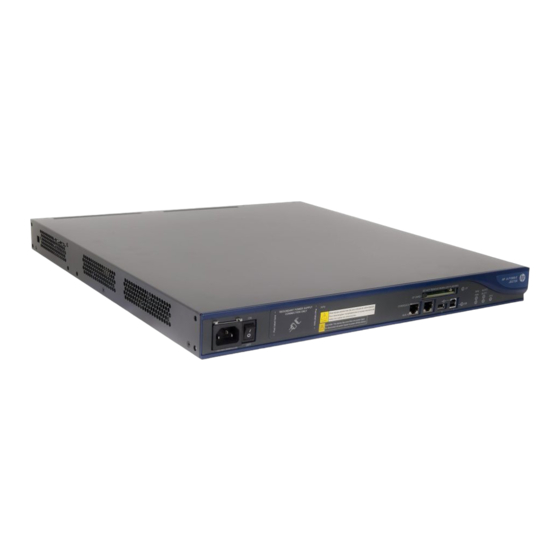
Product overview This chapter describes the HP A-F1000-E VPN firewall and includes these sections: Front panel view • Rear panel view • Front panel view Figure 1 Front panel view (1) AC-input power receptacle (100 VAC to 240 VAC, 50 or 60 Hz at 2.5 A) -
Page 7: Rear Panel View
Rear panel view Figure 2 Rear panel view (1) Grounding screw and grounding sign (2) 1000 Mbps fiber port LED (3) 10/100/1000 Mbps copper port LED (4) Combo copper port (5) Combo SFP fiber port (6) Interface module slot 1 (7) Interface module slot 2... -
Page 8: Preparing For Installation
• Safety recommendations To avoid possible bodily injury and equipment damage, read the safety recommendations in this chapter carefully before installing an A-F1000-E firewall. The recommendations do not cover every possible hazardous condition. This section includes these topics: Safety symbols •... -
Page 9: Safety With Laser
Install a dust plug on the transceiver module to avoid damage to the transceiver module. • Examining the installation site The HP A-F1000-E firewall can only be used indoors. To ensure that the firewall works properly and to prolong its service lifetime, the installation site must meet the following requirements: Temperature and humidity •... -
Page 10: Altitude
Table Table 5 Harmful gas limits in an equipment room Max. (mg/m 0.006 0.05 0.01 Cooling system The HP A-F1000-E firewall adopts left to right airflow for heat dissipation. Figure 3 A-F1000-E airflow... -
Page 11: Esd Prevention
Check the resistance of the ESD-preventive wrist strap for safety. The resistance reading should be in the range of 1 to 10 megohm (Mohm) between human body and the ground. No ESD-preventive wrist strap is provided with the HP A-F1000-E firewall. Prepare it yourself. •... -
Page 12: Emi
All electromagnetic interference (EMI) sources, from outside or inside of the firewall and application system, adversely affect the firewall in a conduction pattern of capacitance coupling, inductance coupling, electromagnetic wave radiation, or common impedance (including grounding system) coupling. To prevent EMI, note the following guidelines: Take measures against interference from the power grid. -
Page 13: Accessories Supplied By The Firewall
NOTE: No installation tool or ESD-preventive wrist strap is provided with the firewall. Prepare them yourself. Accessories supplied by the firewall Rear mounting Front mounting Console cable Grounding cable bracket and bracket and M4 Rubber pads load-bearing screw screws Checklist before installation Table 6 Checklist before installation Item Requirements... - Page 14 Item Requirements Result • The grounding cable of the chassis is well grounded. Lightning • The grounding terminal of the AC power receptacle is protection well grounded. • Equip an uninterrupted power supply (UPS). Electricity safety • In case of emergency during operation, switch off the external power switch.
-
Page 15: Installing The Firewall
Connecting an AC power cord • Connecting an RPS DC power cord • Installation flow Figure 5 HP A-F1000-E firewall installation flow Installing the firewall in a 19-inch rack Installing cage nuts and rear mounting brackets to the rack As shown in Figure 6, install the cage nuts to proper positions on the rack posts. -
Page 16: Installing Front Mounting Brackets And Load-Bearing Screws To The Firewall
Figure 6 Install cage nuts As shown in Figure 7, install the rear mounting brackets to the rear rack posts. Step2 Figure 7 Install rear mounting brackets to the rack Installing front mounting brackets and load-bearing screws to the firewall Before installing the firewall to a rack, install the front mounting brackets and load-bearing screws to the firewall. -
Page 17: Installing The Firewall To The Rack
Align the screw holes on the mounting brackets with the screw holes on the firewall chassis, and then use Step1 a Phillips screwdriver to fasten the screws, as shown in callout 1 in Figure Attach the load-bearing screws to the appropriate screw holes on the firewall chassis, and use a Philips Step2 screwdriver to fasten the screws, as shown in callout 2 in Figure... -
Page 18: Grounding The Firewall
Grounding the firewall WARNING! Correctly connecting the firewall grounding cable is crucial to lightning protection and EMI protection. Follow these steps to connect the grounding cable: Remove the grounding screw from the rear panel of the firewall chassis. Step1 Attach the grounding screw to the OT terminal of the grounding cable. Step2 Use a screwdriver to fasten the grounding screw into the grounding screw hole. -
Page 19: Installing A Cf Card
Figure 11 Install an interface module Use a screwdriver to fasten the captive screws on the interface module. Step3 After the firewall is powered on, check the status LED on the front panel. On means the interface module Step4 is installed correctly and running properly. Off means the interface module has failed the power-on self-test (POST). -
Page 20: Connecting Ethernet Cables
LEDs.” Connecting an optical fiber Before connecting the firewall to the network, you must install a transceiver module to the firewall, and then insert the fiber connector to the transceiver module. The A-F1000-E Firewall supports LC connectors only. WARNING! When connecting an optical fiber, note the following guidelines: Never bend or curve a fiber when connecting it. - Page 21 Figure 13 Remove the dust plug Plug the transceiver module into the SFP interface of the firewall, as shown in Figure Step2 Figure 14 Install the transceiver module Remove the dust cap from the transceiver module and the protective caps from the fibers. Step3 Plug the LC connectors on one end of the fiber cable into the Rx and Tx ports, and plug the LC connectors Step4...
-
Page 22: Connecting An Ac Power Cord
Figure 15 Connect the fiber connectors After the firewall is powered on, check whether the LEDs of the optical interfaces are normal. If the LINK Step5 LED is solid green, you can be sure that the link is connected. For more information about the LED status, see the chapter “Appendix B LEDs.”... -
Page 23: Connecting An Rps Dc Power Cord
Connecting an RPS DC power cord Follow these steps to connect an RPS DC power cord: Check that RPS power source switch is off. Step1 Remove the adhesive tape from the protection cover of the RPS power supply. Step2 Loosen the screws on the RPS receptacle protection cover and remove the protection cover from the Step3 firewall, as shown in Figure... -
Page 24: Logging In To The Firewall And Configuring Basic Settings
Logging in to the firewall and configuring basic settings This chapter includes these sections: • Logging in to the firewall through the console port Logging in to the firewall through Telnet • Powering on the firewall • Logging to the firewall through a web browser •... -
Page 25: Setting Terminal Parameters
Figure 19 Connect the console cable CAUTION: When you connect a PC to a powered-on firewall, connect the DB-9 connector of the console cable to • the PC before connecting the RJ-45 connector to the firewall. When you disconnect a PC from a powered-on firewall, disconnect the DB-9 connector of the console •... - Page 26 Figure 20 Connection description of the HyperTerminal Type the name of the new connection in the Name text box and click OK. The following dialog box Step2 appears. Select the serial port to be used from the Connect using drop-down list. Figure 21 Set the serial port used by the HyperTerminal connection Click OK after selecting a serial port and the following dialog box appears.
- Page 27 Figure 22 Set the serial port parameters Click OK after setting the serial port parameters and the system enters the following interface. Step4 Figure 23 HyperTerminal window Click Properties in the HyperTerminal window to enter the aaa Properties dialog box. Click the Settings Step5 tab, set the Emulation to VT100, and then click OK.
-
Page 28: Powering On The Firewall
IP address of port GigabitEthernet 0/0: 192.168.0.1/24 Follow these steps to log in to the firewall through Telnet: Log in to the A-F1000-E through the console port and then use the telnet server enable command in Step1 system view to enable the Telnet function of the firewall. -
Page 29: Logging To The Firewall Through A Web Browser
Connect a cable to the A-F1000-E. Step1 Connect the Ethernet interface GigabitEthernet 0/0 of the A-F1000-E to a PC by using a network cable. Configure an IP address for the PC, ensuring the PC and the A-F1000-E can ping each other. -
Page 30: Launching The Basic Configuration Wizard
Launching the basic configuration wizard Select Wizard from the navigation tree to enter the Configuration Wizard page, and then click the Basic Device Information hyperlink to enter the first page of the basic configuration page, as shown in Figure Figure 25 Basic configuration wizard: 1/6 Configuring the system name and user password Click Next on the first page of the basic configuration wizard to enter the basic information configuration page, as shown in... -
Page 31: Configuring Service Management
Table 7 Basic information configuration items Item Description Sysname Set the system name. By default, the system name of the firewall is HP. Modify Current User Specify whether to modify the login password of the current user. Password To modify the password of the current user, set the new password and the confirm New Password password, and the two passwords must be identical. - Page 32 Figure 27 Basic configuration wizard: 3/6 (service management) Table 8 Service management configuration items Item Description Specify whether to enable FTP on the device. Disabled by default. Specify whether to enable telnet on the device. Telnet Disabled by default. Specify whether to enable HTTP on the device, and set the HTTP port number. Enabled by default.
-
Page 33: Configuring The Ip Address For An Interface
Item Description Specify whether to enable HTTPS on the device, and set the HTTPS port number. HTTPS is the HTTP protocol that supports the Secure Sockets Layer (SSL) protocol. It can improve device security. Disabled by default. IMPORTANT: If the current user logged in to the web interface through HTTPS, disabling •... -
Page 34: Configuring Nat
Table 9 Interface IP address configuration items Item Description Set the approach for obtaining the IP address, including: • None: The IP address of the interface is not specified, that is, the interface has no IP address. • Static Address: Specify the IP address for the interface IMPORTANT: manually;... -
Page 35: Completing The Configuration Wizard
Table 10 NAT configuration items Item Description Select an interface on which the NAT configuration will be applied. Generally, it is Interface the outgoing interface of the device. Specify whether to enable dynamic NAT on the interface. If dynamic NAT is enabled, the IP address of the interface will be used as the IP Dynamic NAT address of a matched packet after the translation. - Page 36 Figure 30 Basic configuration wizard: 6/6 On this page, you can set whether to save the current configuration to the startup configuration file (which can be .cfg or .xml file) for the next device boot when you submit the configurations. This page lists all configurations you have made in the basic configuration wizard.
-
Page 37: Hardware Management And Maintenance
Hardware management and maintenance This chapter includes these sections: Displaying detailed information about the firewall • Displaying software and hardware version information of the firewall • Displaying the electrical label information of the firewall • • Displaying the CPU usage of the firewall Displaying the memory usage of the firewall •... -
Page 38: Displaying Software And Hardware Version Information Of The Firewall
HP Comware Platform Software Comware Software, Version 5.20, Release 3166P13 Copyright (c) 2010-2011 Hewlett-Packard Development Company, L.P. HP A-F1000-E uptime is 0 week, 0 day, 0 hour, 15 minutes CPU type: xxxx 1024M bytes DDR2 SDRAM Memory 4M bytes Flash Memory 495M bytes CF0 Card Version:Ver.B... -
Page 39: Displaying The Cpu Usage Of The Firewall
Displaying the CPU usage of the firewall Use the display cpu-usage command to display the CPU usage of a firewall. <Sysname> display cpu-usage Unit CPU usage: 1% in last 5 seconds 1% in last 1 minute 1% in last 5 minutes Table 11 Output description Field Description... -
Page 40: Displaying The Operational Status Of The Fans
Field Description Size Storage capacity of the CF card Displaying the operational status of the fans Use the display fan command to display the operational status of the fans. <Sysname> display fan 1 State: Normal Table 13 Output description Field Description Number of the fan The fan state:... -
Page 41: Displaying Operational Statistics Of The Firewall
SlotNo Temperature Lower limit Upper limit Field Description System Temperature information (degree centigrade) System temperature (°C) SlotNO Number of the slot holding the interface module Temperature Current temperature Lower limit Lower threshold Upper limit Upper threshold Displaying operational statistics of the firewall When you perform routine maintenance or the system fails, you may need to display the operational information of each functional module for locating failures. -
Page 42: Rebooting The Firewall
during the process. The fast saving mode is suitable for environments where the power supply is stable. • Safe saving: Executing the save command with the safely keyword. The mode saves the file more slowly but can retain the configuration file in the device even if the device reboots or the power fails during the process. - Page 43 CAUTION: If the main host software file is not specified, do not use the reboot command to reboot the firewall. In • this case, you should specify the main host software file first, and then reboot the firewall. The precision of the rebooting timer is 1 minute. One minute before the rebooting time, the firewall •...
-
Page 44: Replacement Procedures
Replacement procedures This chapter includes these sections: Safety recommendations • Replacing an interface module • Replacing a CF card • • Replacing a transceiver module Safety recommendations Always wear an ESD-preventive wrist strap or ESD-preventive gloves when maintaining the firewall hardware. -
Page 45: Replacing A Cf Card
Figure 31 Remove an interface module If you do not install a new interface module in the slot, install two blank panels. To install an interface Step3 module, see the chapter “Installing the firewall.” Replacing a CF card Follow these steps to replace a CF card: Make sure that the CF card LED is not blinking. -
Page 46: Replacing A Transceiver Module
Figure 33 Press the eject button to eject the CF card Install a new CF card. For more information, see the chapter “Installing the firewall.” Step4 CAUTION: • To avoid hardware damage, do not remove the CF card when the firewall is booting or the CF card LED is blinking. - Page 47 Figure 34 Remove a transceiver module...
-
Page 48: Troubleshooting
Keep the tamper-proof seal on a mounting screw on the chassis cover intact, and if you want to open the • chassis, contact the local agent of HP for permission. Otherwise, HP shall not be liable for any consequence caused thereby. -
Page 49: Configuration Terminal Problems
Configuration terminal problems If the configuration environment setup is correct, the configuration terminal displays boot information when the firewall is powered on. If the setup is incorrect, the configuration terminal displays nothing or garbled text. No terminal display If the configuration terminal displays nothing when the firewall is powered on, check the following items: The power supply system works properly. -
Page 50: Password Loss
To save the new password, execute the save command after modifying the user password. • • HP recommends saving the modification as the default configuration file. Super password loss You can clear the super password by selecting 8 on the BootWare main menu. -
Page 51: Cooling System Failure
If the temperature inside the firewall exceeds 80°C (176°F), the following information appears on the Step3 configuration terminal: %May 19 19:38:59:134 2011 HP DRVMSG/3/Temp2High:Temperature Point 0/1 Too High. #May 19 19:39:03:227 2011 HP DEV/1/BOARD TEMPERATURE UPPER: Trap 1.3.6.1.4.1.25506.8.35.12.1.16: chassisIndex is 0, slotIndex 0.0 %May 19 19:39:03:228 2011 HP DEV/4/BOARD TEMP TOOHIGH: Board temperature is too high on Chassis 0 Slot 0, type is RPU. - Page 52 Check whether the interface module cable is correctly selected. Step1 Check whether the interface module cable is correctly connected. Step2 Use the display command to check whether the interface has been correctly configured and is working Step3 properly.
-
Page 53: Appendix A Technical Specifications
Appendix A Technical specifications Dimensions and weight Table 16 Dimensions and weight Item Specification 44 mm (1.73 in), which is approximately one rack Height (H) unit Width (W) 442 mm (17.40 in) Depth (D) 463 mm (18.23 in) Weight 7.5 kg (16.53 lb) Storages Table 17 Storages Item... -
Page 54: Rps Power Supply (Optional)
The default working port of a combo interface is the copper port. Console port The A-F1000-E firewall provides an RS-232 asynchronous serial console port that can be connected to a computer for system debugging, configuration, maintenance, management, and host software loading. -
Page 55: Aux Port
AUX port The AUX port is an RS-232 asynchronous serial port used for remote configuration or dialup backup. You must connect the local modem to the remote modem through public switched telephone network (PSTN) and then to the remote device for remote system debugging, configuration, maintenance, and management. - Page 56 Table 25 Technical specifications for 1000 Mbps fiber Ethernet ports Item Specification Connector SFP/LC Compliant 802.3, 802.3u, and 802.3ab standard Short-haul Medium-haul Ultra-long Long-haul Long-haul multi-mode single-mode haul optical optical module optical module Type optical Optical optical module module (1550 module (850 (1310 nm) (1550 nm)
-
Page 57: Appendix B Leds
Appendix B LEDs Front panel LEDs Table 26 Description of front panel LEDs Status Meaning No RPS DC power input. RPS power LED Solid green Both AC power input and RPS DC input are normal. (yellow/green) AC power input is abnormal, and RPS DC input is Solid yellow normal. - Page 58 Status Meaning Data is being received or transmitted at a rate of 10/100 Flashing yellow Mbps. No link is present. Solid green A 1000 Mbps link is present. Ethernet fiber Data is being received or transmitted at a rate of 1000 port LED Flashing green Mbps.
-
Page 59: Appendix C Interface Modules
Appendix C Interface modules HP A-F1000-E VPN firewall provides two interface module slots, and supports the 4GBE, 8GBE, 1EXP, and 4GBP hot-swappable interface modules. Hot swapping refers to using the remove slot number command to stop an interface module from working and then unplugging the interface module, and plugging an interface module without powering off the device. - Page 60 Figure 36 Front panel of 8GBE (1) Captive screw (2) GE interface (3) GE interface status LED (4) Ejector lever LEDs Table 28 Description of the LEDs on the front panel of 4GBE/8GBE Status Meaning No link is present. Solid green A 1000 Mbps link is present.
-
Page 61: 4Gbp
Interface calbes For how to connect a 4GBE/8GBE interface cable, see “Installing the firewall.” 4GBP Introduction A 4GBP high-speed Layer 3 Gigabit Ethernet interface module provides four Small Form-Factor Pluggable (SFP) interfaces. Each interface is provided with an LED, which indicates the running status of the interface. -
Page 62: 1Exp
Item Specification Max. 0 dBm –3 dBm 5 dBm 1 dBm 2 dBm Receiving sensitivity –17 dBm –20 dBm –23 dBm –21 dBm –22 dBm Central wavelength 850 nm 1310 nm 1310 nm 1550 nm 1550 nm 62.5/125 μm 9/125 μm 9/125 μm 9/125 μm 9/125 μm... - Page 63 Front panel Figure 39 Front panel of 1EXP (1) Captive screw (2) XFP interface (3) Carrier signal LED (LINK/ACT) of XFP (4) Ejector lever LEDs Table 32 Description of the LED on the front panel of 1EXP Status Meaning No link is present. Solid green A link is present, but no data is being received or transmitted.
- Page 64 Interface cables A 1EXP module must use an XFP transceiver module and fibers with LC connectors. For how to connect an optical fiber, see “Installing the firewall.” Figure 40 XFP transceiver module...
-
Page 65: Appendix D Ac Power Cables Used In Different Countries Or Regions
Appendix D AC power cables used in different countries or regions 10A AC power cables used in different countries or regions Table 34 10A AC power cables used in different countries or regions Countries or regions where the type of power Other countries or Countries or regions Connect... - Page 66 Holland, Denmark, Sweden, Finland, 04041056 (3 Indonesia, Turkey, F type Norway, Germany, India m, i.e., 9.8 ft) Russia, and CIS France, Austria, Belgium, and Italy Connector outline Power cable outline Connector outline Countries or regions where the type of power Other countries or Countries or regions Connect...
- Page 67 Connector outline Power cable outline Connector outline Countries or regions where the type of power Other countries or Countries or regions Connect cables conforms to local regions using this type seldom using this type of Code (Length) or type safety regulations and of power cables power cables can be used legally...
-
Page 68: Ac Power Cables Used In Different Countries Or Regions
16A AC power cables used in different countries or regions Table 35 16A AC power cables used in different countries or regions Countries or regions where the type of Countries or Other countries or Connector power cables regions seldom Code (Length) regions using this type of type conforms to local... - Page 69 Holland, Denmark, Sweden, Finland, 0404A061 (3 Indonesia, Turkey, F type Norway, Germany, m, i.e., 9.8 ft) Russia, and CIS France, Austria, Belgium, and Italy Connector outline Power cable outline Connector outline Countries or regions where the type of Countries or Other countries or Connector power cables...
- Page 70 0404A01A (3 I type Australia m, i.e., 9.8 ft) Connector outline Power cable outline Connector outline...
-
Page 71: Support And Other Resources
Related information Documents To find related documents, browse to the Manuals page of the HP Business Support Center website: http://www.hp.com/support/manuals For related documentation, navigate to the Networking section, and select a networking category. •... -
Page 72: Conventions
Conventions This section describes the conventions used in this documentation set. Command conventions Convention Description Boldface Bold text represents commands and keywords that you enter literally as shown. Italic Italic text represents arguments that you replace with actual values. Square brackets enclose syntax choices (keywords or arguments) that are optional. Braces enclose a set of required syntax choices separated by vertical bars, from which { x | y | ... - Page 73 Network topology icons Represents a generic network device, such as a router, switch, or firewall. Represents a routing-capable device, such as a router or Layer 3 switch. Represents a generic switch, such as a Layer 2 or Layer 3 switch, or a router that supports Layer 2 forwarding and other Layer 2 features.
-
Page 74: Index
Installing interface modules,13 Connecting Ethernet cables,15 Installing the firewall in a 19-inch rack,10 Contacting HP,66 Interface module, cable, and connection failure,46 Conventions,67 Cooling system failure,46 Logging in to the firewall through Telnet,23 Logging in to the firewall through the console... - Page 75 Storages,48 Using the AUX port as backup console port,44...