
Related Manuals for Struers Duramin-40


Summary of Contents for Struers Duramin-40
- Page 1 Duramin-40 Instruction Manual Original Instructions Doc. no.: 16607025_D_en Date of release: 2021.02.08...
- Page 2 Copyright The contents of this manual are the property of Struers ApS. Reproduction of any part of this manual without the written permission of Struers ApS is not allowed. All rights reserved. © Struers ApS 2021.02.08. Duramin-40...
-
Page 3: Table Of Contents
5.7 Mounting an XY-stage 5.8 Power supply 5.8.1 Connection to the machine 5.9 Noise 5.10 Vibration 6 Operating the device 6.1 Main screen 6.2 Front panel controls 6.3 Starting up Duramin-40 6.4 Mounting an indenter 6.5 Performing a basic test Duramin-40... - Page 4 7 Maintenance and service - Duramin-40 7.1 General cleaning 7.1.1 Daily 7.2 Weekly 7.2.1 Cleaning the monitor 7.2.2 Weekly inspection 7.3 Annually 7.3.1 Maintenance 7.3.2 Testing safety devices 7.3.3 Emergency stop 7.3.4 Calibration 7.4 Service and repair 7.4.1 Spare parts 7.4.2 Replacing the fuse...
- Page 5 11.0.9 Power supply 11.0.10 Connection to the machine 11.0.11 Safety specifications 11.0.12 Duramin-40 - Drilling guide 12 Manufacturer Declaration of Conformity Duramin-40...
-
Page 6: About This Manual
1 About this manual About this manual Instruction Manuals Struers equipment must only be used in connection with and as described in the instruction manual supplied with the equipment. Note Read the instruction manual carefully before use. Note If you wish to view specific information in detail, see the online version of this manual. -
Page 7: Duramin-40 Safety Precautions
16. Disconnect the machine from the power supply before cleaning it. Failure to do so can result in electric shock. 17. Struers equipment must only be used in connection with and as described in the instruction manual supplied with the equipment. -
Page 8: Safety Messages
This sign indicates that additional information and hints are available. Safety messages in this manual WARNING Struers equipment must only be used in connection with and as described in the instruction manual supplied with the equipment. CRUSHING HAZARD Take care of your fingers when handling the machine. -
Page 9: Getting Started
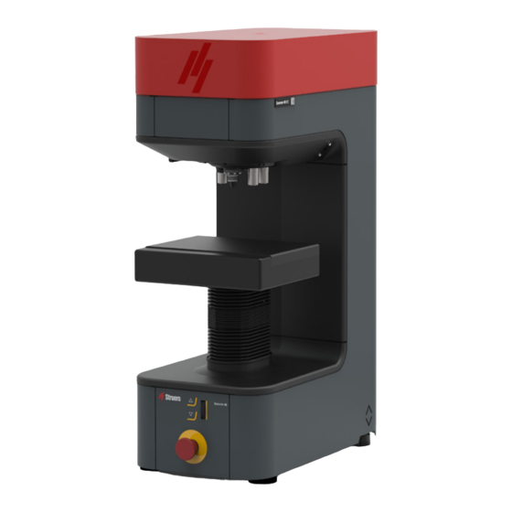
Getting started Device description Duramin-40 offers a technology base for manual, semi-automatic or fully automated testing of Micro and Macro Vickers, Knoop or Brinell assignments. The specimen is placed on the anvil/XY-stage, and the desired testing pattern is set up using the testing software. -
Page 10: Overview
E Connection for motorized XY-stage F Z-axis and focus control G Emergency stop Rear view A Power indicator B Power cable adapter C Power cable adapter, Monitor D USB ports E HDMI connector F Connector, Monitor G Internet connector Duramin-40... -
Page 11: Transport And Storage
Insufficient packaging could cause damage to the unit and will void the warranty. Contact Struers Service. • Struers recommends that all original packaging and fittings are kept for future use. Transport • Disconnect the unit from the electrical power supply. -
Page 12: Long-Term Storage Or Shipping
At the new location, make sure that the facilities required are in place. See also: Location ►40. Installation WARNING Struers equipment must only be used in connection with and as described in the instruction manual supplied with the equipment. Unpacking Note Struers recommends that all original packaging and fittings are kept for future use. -
Page 13: Checking The Packing List
Some components or parts can be packaged separately and may not be included in the accessories case or may be installed on the machine. Optional accessories may be included in the packing box. The packing box contains the following items: Duramin-40... -
Page 14: Lifting
5 Installation Pcs. Description Duramin-40 Accessories case Monitor, 15", (option) Instruction Manual set Accessories case Pcs. Description Indenters Objective lens Allen key 0.9 mm Z-spindle limiter bracket Mouse, (option) Power supply cables Spare fuse Calibration certificate (on memory stick) WiFi adapter... - Page 15 Support the lifting bar and remove the screws and washers from both sides of the bar using a 5 mm Allen key. Remove the transport protection of the XY-stage. Note Struers recommends that all original packaging and fittings are kept for future use. Duramin-40...
-
Page 16: Location
2: Spindle protrusion 140 mm (5.5”) Note If you wish to use the maximum spindle capacity, you must drill a hole in the table top to accommodate the full stroke of the spindle. See also: Duramin-40 - Drilling guide ►49 Duramin-40... -
Page 17: Placing The Machine
Removing the transport safety plate Note Only for motorized XY-stage option. Remove the transport safety plate before you switch on the machine. CAUTION The XY-stage will be damaged if the transport safety plate is not removed before you switch on the machine. Duramin-40... -
Page 18: The Monitor (Option)
XY-stage. Use an 2.5 mm (0.1") Allen key. Struers recommends that all original packaging and fittings are kept for future use. When you switch on the machine, the XY-stage will automatically move to perform a reference search. - Page 19 In the Duramin software, select System > Settings, and make sure that the option XY- stage is checked. Note The range of force that can be applied is limited when using a XY-stage. Excessive overload can result in irreparable damage to the machine. Duramin-40...
-
Page 20: Power Supply
5.8.1 Connection to the machine • Connect the electrical power cable to the machine (C14 IEC 320 connector). • Connect the cable to the electrical power supply. Duramin-40... -
Page 21: Noise
Do not place your hand between the sample and the indenter. CRUSHING HAZARD Do not hold on to the XY-stage or the anvil while you are using the machine. Electrical power switch The electrical power switch is located on the rear of the machine. Duramin-40... -
Page 22: Main Screen
Test settings The Test Settings menu is used to select test settings, such as dwell time, patterns, etc. Graphs/diagrams The Graphs/diagrams window shows a graph of the results obtained. Duramin-40... -
Page 23: Front Panel Controls
A Spindle up/down keys B Emergency stop C Scroll wheel for fine focus Starting up Duramin-40 Switch on the hardness tester using the electrical power switch at the rear. The software will initialize and you will see the progress bar on the monitor. -
Page 24: Mounting An Indenter
Always keep indenters in their case when you are not using them, otherwise they can be damaged. Checking the indenter length Start the Duramin software. Focus on a smooth test sample using the highest magnification available. Select Tester > Turret configuration. Duramin-40... -
Page 25: Performing A Basic Test
Press Stop if you want to stop the test. After the indent is made, the software automatically measures the indent and displays the result. The measured hardness value is displayed in the Test Result and in the Graph sections. Duramin-40... -
Page 26: Maintenance And Service - Duramin-40
You can also find this information in the Duramin software by selecting Tester > Info. General cleaning To ensure a longer lifetime for your machine, Struers strongly recommends regular cleaning. Note Do not use a dry cloth as the surfaces are not scratch resistant. -
Page 27: Weekly
7 Maintenance and service - Duramin-40 Weekly • Clean the front panel, the anvil and the XY-stage with a soft damp cloth and common household detergents. 7.2.1 Cleaning the monitor The touch screen Wipe the screen using a soft, clean cloth moistened with window cleaner. -
Page 28: Emergency Stop
Service and repair Struers recommends that a regular service check be carried out yearly or after every 1500 hours of use. Note Service must only be performed by a Struers engineer or a qualified technician (electromechanical, electronic, mechanical, pneumatic, etc.). -
Page 29: Spare Parts
If you have technical questions or when you order spare parts, state serial number and voltage/frequency. The serial number and the voltage are stated on the type plate of the machine. For further information, or to check the availability of spare parts, contact Struers Service. Contact information is available on Struers.com. -
Page 30: Troubleshooting - Duramin-40
Objective image flickers Go to Visuals > Contrast, and deselect Automatic. If the error remains, contact Struers Service. Most/all buttons are grayed out when The machine settings file is most likely starting up the software corrupted due to an improper shutdown. - Page 31 8 Troubleshooting - Duramin-40 Issue Action Timeout message shown: Restart the software to reset the USB bus. The problem could be caused by the Trinamic timeout removal of a USB device. Use a different Timeout Depthmeter Readout USB port for the USB drive or use a different USB drive.
-
Page 32: Technical Data
When in Focus on a sample and switching Perform an objective focus distance to the indenter, the stage moves up and the calibration sample touches the indenter Technical data Technical data - Duramin-40 Subject Specifications Electrical data Power supply 100 V AC – 240 V AC, 50/60Hz, single phase Power consumption Max. -
Page 33: Specifications
9 Technical data Specifications Force ranges Duramin-40 M1/A1/AC1 10gf - 10 kgf Duramin-40 M2/A2/AC2 10gf - 31.21kgf Duramin-40 M3/A3/AC3 1gf - 62.5kgf Hardness methods VICKERS ISO 6507 ASTM E384, E92 JIS B 7725 KNOOP ISO 4545 ASTM E92 JIS Z 2251... -
Page 34: System
SRP/CS (safety-related parts of a control system) are parts that have an influence on safe operation of the machine. Note Replacement of safety critical components must only be performed by a Struers engineer or a qualified technician (electromechanical, electronic, mechanical, pneumatic, etc.). -
Page 35: Diagrams
Total vibration exposure to upper parts of the body does not exceed 2.5 m/s Diagrams If you wish to view specific information in detail, see the online version of this manual. 9.5.1 Diagrams - Duramin-40 Title Duramin-40, Block diagram 16603050 B Duramin-40... - Page 36 DK-2750 Ballerup DK-2750 Ballerup DK-2750 Ballerup Denmark Denmark Denmark telephone: +45 44 600 800 telephone: +45 44 600 800 telephone: +45 44 600 800 Duramin-40, Block Diagram Duramin-40, Block Diagram Duramin-40, Block Diagram SSD1 SSD2 Size Size Size CAGE Code...
-
Page 37: Legal And Regulatory Information
Reorient or relocate the receiving antenna. • Increase the separation between the equipment and receiver. • Connect the equipment into an outlet on a circuit different from that to which the receiver is connected. 10 Drilling guide 10.1 Duramin-40 - Drilling guide Duramin-40... - Page 38 10 Drilling guide Duramin-40...
-
Page 39: 11 Pre-Installation Checklist
11 Pre-installation checklist 11 Pre-installation checklist Duramin-40... -
Page 40: Installation Requirements
To facilitate easy access for service technicians, allow sufficient space around the machine. Supply requirements The machine must be placed close to the power supply. Supply type Required Not required Power supply Required Water supply Not required Waste water outlet Not required Compressed air Not required Exhaust Not required Duramin-40... - Page 41 If you wish to use the maximum spindle capacity, you must drill a hole in the table top to accommodate the full stroke of the spindle. See also: Duramin-40 - Drilling guide ►49 Vibration Vibrations can lead to inaccurate measurements and must therefore be avoided.
-
Page 42: Dimensions
11 Pre-installation checklist 11.0.4 Dimensions Duramin-40 Front view Side view Duramin-40... -
Page 43: Recommended Space
11 Pre-installation checklist Footprint - Duramin-40 Seen from above Feet - Front view Feet - Side view 11.0.5 Recommended space Space in front of the machine • Make sure that there is enough room in front of the 100 cm/40”... -
Page 44: Transport And Storage
• Package the unit securely before transportation. Insufficient packaging could cause damage to the unit and will void the warranty. Contact Struers Service. • Struers recommends that all original packaging and fittings are kept for future use. -
Page 45: Unpacking
At the new location, make sure that the facilities required are in place. See also: Location ►40. 11.0.7 Unpacking Note Struers recommends that all original packaging and fittings are kept for future use. Note • Be careful when you handle the machine. • Do not drop or damage the machine. -
Page 46: Lifting
The lifting straps must be approved to lift at least twice the weight of the machine. Use a crane and lifting straps to lift the machine from the packing box. Make sure that the crane has a free pathway from the lifting point to the workbench. Duramin-40... - Page 47 Support the lifting bar and remove the screws and washers from both sides of the bar using a 5 mm Allen key. Remove the transport protection of the XY-stage. Note Struers recommends that all original packaging and fittings are kept for future use. Duramin-40...
- Page 48 11.0.10 Connection to the machine • Connect the electrical power cable to the machine (C14 IEC 320 connector). • Connect the cable to the electrical power supply. Duramin-40...
- Page 49 11 Pre-installation checklist Electrical power connection A Electrical power switch B Electrical power socket/ Fuse compartment C Electrical power connection, Monitor 11.0.11 Safety specifications Safety Circuit Emergency stop EN ISO 13849-1 PL c, Category 1 Categories/Performance Stop category 0 Level 11.0.12 Duramin-40 - Drilling guide Duramin-40...
- Page 50 11 Pre-installation checklist Duramin-40...
-
Page 51: 12 Manufacturer
Responsibility of the manufacturer The following restrictions should be observed, as violation of the restrictions may cause cancellation of Struers legal obligations. The manufacturer assumes no responsibility for errors in the text and/or illustrations in this manual. The information in this manual is subject to change without notice. The manual may mention accessories or parts not included in the supplied version of the equipment. -
Page 52: Declaration Of Conformity
Based on: 16607901 F Struers ApS Pederstrupvej 84 DK-2750 Ballerup, Denmark Declaration of Conformity EU / UE / EL / EC / EE / ES / EÚ / AB Manufacturer / Производител / Výrobce / Producent / Hersteller / Κατασκευαστής / Fabricante / Tootja / Valmistaja / Fabricant / Proizvođač / Gyártó / Fabbricante / Gamintojas / Ražotājs / Fabrikant / Producent / Fabricante / Producătorul / Výrobca / Proizvajalec / Tillverkare / 販...
Need help?
Do you have a question about the Duramin-40 and is the answer not in the manual?
Questions and answers