
Related Manuals for Satel VERSA Plus LTE


Summary of Contents for Satel VERSA Plus LTE
- Page 1 INSTALLER MANUAL versa_plus_lte_i_en 09/21 SATEL sp. z o.o. ul. Budowlanych 66 • 80-298 Gdańsk • POLAND tel. +48 58 320 94 00 www.satel.eu...
- Page 2 Please visit us: https://support.satel.eu Hereby, SATEL sp. z o.o. declares that the radio equipment type VERSA Plus LTE is in compliance with Directive 2014/53/EU. The full text of the EU declaration of conformity is available at the following internet address: www.satel.eu/ce...
-
Page 3: Table Of Contents
CONTENTS Introduction ........................3 Features ........................... 3 Keypads ........................... 5 Keypads features ....................... 6 Expansion modules ......................7 System installation ......................7 Installation plan ......................7 Estimation of the system current consumption ............7 Cabling ........................8 Installation of control panel mainboard ..............8 5.4.1 Description of the mainboard ................ - Page 4 VERSA Plus LTE SATEL Numeration of zones and outputs in the system ............34 Numeration of zones ....................34 6.1.1 Hardwired zones ....................34 6.1.2 Wireless zones ....................34 Numeration of outputs ..................... 35 6.2.1 Hardwired outputs .................... 35 6.2.2 Wireless outputs ....................
-
Page 5: Introduction
VERSA Plus LTE 1. Introduction This manual describes the VERSA Plus LTE control panel and how it should be installed. In addition, the manual provides information about devices compatible with the control panel and how they are to be connected. - Page 6 VERSA Plus LTE SATEL • Dual SIM (nano-SIM) support by cellular communicator. • Built-in 300 bps modem. Reporting • Reporting events to two monitoring stations: – several communication formats (including Contact ID and SIA), – 4 identifiers. • Multiple transmission paths: –...
-
Page 7: Keypads
– firmware update for the control panel and built-in modules. • Removable terminals. 3. Keypads SATEL offers the following keypads for VERSA Plus LTE alarm control panels: INT-TSG – hardwired touchscreen keypad, INT-TSG2 – hardwired touchscreen keypad, INT-TSH – hardwired touchscreen keypad,... -
Page 8: Keypads Features
For information on the INT-TSG, INT-TSG2, INT-TSH, INT-TSH2, VERSA-KWRL2 and VERSA-LCDM-WRL keypads, please refer to the manuals delivered with the keypads. Fig. 1. Examples of keypads supported by the VERSA Plus LTE control panel. Keypads features • Display 2 x 16 characters with backlight. -
Page 9: Expansion Modules
SATEL VERSA Plus LTE • Built-in proximity card reader. VERSA-LCDR • Tamper contact reacting to the enclosure opening or detaching from the wall. 4. Expansion modules INT-RX-S / INT-RX. 433 MHz keyfobs receiver expansion module. Enables operation of the alarm system using the 433 MHz keyfobs. -
Page 10: Cabling
VERSA Plus LTE SATEL If the sum of currents exceeds the maximum output current of the control panel power supply, expander with power supply or an additional power supply unit should be used. The sum of currents consumed by the devices connected to the power supply unit (expander with power supply) must not exceed the power supply output current. -
Page 11: Description Of The Mainboard
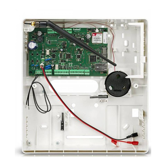
SATEL VERSA Plus LTE 5.4.1 Description of the mainboard Fig. 2. Mainboard of the control panel. battery connection cables (red +, black -). BATTERY CHARGE LED. Indicates that the battery is charging. a group of dedicated terminals for connecting the ABAX 2 (ACU-220 / ACU-280) / ABAX (ACU-120 / ACU-270 / ACU-100 / ACU-250) / MICRA (VERSA-MCU) wireless system controller. -
Page 12: Connecting Devices To The Communication Bus
VERSA Plus LTE SATEL ETHM LED: OFF – Ethernet communicator is disabled, ON – Ethernet communicator is enabled. SIM LED: OFF – cellular communicator is disabled, single flash – cellular communicator is enabled, SIM 1 card is active, double flash – cellular communicator is enabled, SIM 2 card is active. -
Page 13: Connecting Hardwired Keypads
SATEL VERSA Plus LTE The device can be powered directly from the control panel, if the distance to the control panel does not exceed 300 m. Where the distance is greater, another power source must be provided for the device (power supply or expander with power supply). -
Page 14: Connecting 433 Mhz Keyfobs Receiver Expansion Module
VERSA Plus LTE SATEL Fig. 3. Connecting keypads to the control panel. 5.5.2 Connecting 433 MHz keyfobs receiver expansion module One INT-RX-S or INT-RX expansion module can be connected to the control panel. The module enables 433 MHz keyfobs to be assigned to the users (up to 30 keyfobs). Address 7 (07h) must be set in the module. -
Page 15: Connecting Abax 2 / Abax Wireless System Controller
SATEL VERSA Plus LTE can support up to 30 wireless zones. If the wireless zone number coincides with that of the wired zone (on mainboard or in expander), the wireless zone is supported. The controller DIP-switches are not used. The VERSA-MCU controller is identified by the control panel as two devices: INT-RX (address 7) and VERSA-MCU (address 8). -
Page 16: Connecting The Hardwired Zone Expanders
VERSA Plus LTE SATEL Fig. 7. Connecting the ACU-220 / ACU-280 / ACU-120 / ACU-270 controller to the control panel. Fig. 8. Connecting the ACU-100 / ACU-250 controller to the control panel. Fig. 9. Setting the DIP-switches in the ABAX 2 / ABAX controllers. - Page 17 SATEL VERSA Plus LTE • define how the expander is to be identified – switch 10 (INT-E) or 8 (CA-64 E / CA-64 EPS). For detailed information on how the expander will be identified and what are the functional differences resulting from the identification, please refer to the manual delivered with the expander.
-
Page 18: Connecting The Hardwired Output Expander
VERSA Plus LTE SATEL Expander address Zone numbers decimally hexadecimally 7-14 15-22 23-30 Table 2. 5.5.6 Connecting the hardwired output expander One INT-O / INT-ORS / CA-64 O / CA-64 OPS expander can be connected to the control panel. This enables expansion of the system by adding 8 programmable wired outputs. -
Page 19: Connecting The Detectors
SATEL VERSA Plus LTE Fig. 14. Connecting the INT-IT / INT-IT-2 module to the control panel. Fig. 15. Setting the address, as in the case of the INT-IT / INT-IT-2 module. Connecting the detectors How the detector is connected to the zone must be suitable for the configuration chosen for that zone. - Page 20 VERSA Plus LTE SATEL Fig. 16. The ways to connect detectors to zones. The detector outputs are designated with letters: A - alarm, T – tamper. R=R1+R2. VERSA Plus LTE Fig. 17. Example of connecting an NC detector (NO detector connect in the same way).
- Page 21 SATEL VERSA Plus LTE VERSA Plus LTE Fig. 18. Example of connecting an NC detector in Single EOL configuration. VERSA Plus LTE Fig. 19. Example of connecting an NO detector in Single EOL configuration.
-
Page 22: End-Of-Line Resistors
VERSA Plus LTE SATEL VERSA Plus LTE Fig. 20. Example of connecting an NC detector in Double EOL (2EOL) configuration (NO detector connect in the same way). 5.6.1 End-of-line resistors For the control panel mainboard zones, use a 2.2 kΩ resistor in Single EOL configuration and two 1.1 kΩ... -
Page 23: Connecting The Radio Monitoring Transmitter
OUT 3/4 global option must be enabled in the control ERIAL DATA ON panel (see P manual). Table 3 contains description of the connector contacts in ROGRAMMING the NOKTON NR2-DSC transmitter, used for connecting to the VERSA Plus LTE control panel. Contact Description Connection method... -
Page 24: Connecting The Analog Telephone Line
VERSA Plus LTE SATEL Fig. 22. Connecting the NOKTON NR2-DSC transmitter to the control panel. The DB-15 female connector is shown from the solder side. Connecting the analog telephone line Do not send telephone signals and alarm system signals by one multicore cable. -
Page 25: Connecting The Ethernet Network
SATEL VERSA Plus LTE Fig. 23. Connecting analog telephone line to the control panel. 5.10 Connecting the Ethernet network The device is designed to be used only in the local area networks (LAN). It must not be connected directly to the public computer network (MAN, WAN). For establishing connection with public networks, use a router or xDSL modem. - Page 26 VERSA Plus LTE SATEL Fig. 24. Opening the INT-AVT terminal enclosure. 2. Disconnect the speaker plug from the electronics board. 3. Put the enclosure base to the wall and mark the location of mounting holes. 4. Drill the holes for wall plugs (screw anchors).
-
Page 27: Connecting The Power Supply And Starting The Control Panel
SATEL VERSA Plus LTE 5.12 Connecting the power supply and starting the control panel Do not connect power until all installation operations are completed. 5.12.1 Main power supply The control panel requires 18 VAC (±10%) power supply. It is recommended that a transformer with up to 40 VA rating be used. -
Page 28: Emergency Procedure Of The Control Panel Start-Up
VERSA Plus LTE SATEL If it is necessary to de-energize the control panel, turn off the main power supply (AC) first, and the backup power supply (battery) afterwards. Observe the above described procedure when reconnecting the power supply. 5.12.4 Emergency procedure of the control panel start-up If the control panel fails to start properly, keypads are not supported, codes are not accepted by the control panel etc., despite all connections having been made correctly, follow the steps... -
Page 29: Programming The Address Without Entering The Service Mode
SATEL VERSA Plus LTE 1. Enter the service code (by default 12345) and press the key. 2. Press in turn the keys. The service mode will start. 3. Press in turn the keys. The K . function will start. All... -
Page 30: Identification Of Devices Connected To The Bus
VERSA Plus LTE SATEL 5. Press the key with the number corresponding to the new address. The address change will be confirmed by four short beeps followed by a long one. Pressing allow to change the address again (the keypad restart will follow and information on the current address will be displayed again). -
Page 31: Connecting The Computer To The Control Panel
SATEL VERSA Plus LTE If the SIM card requires entering the PIN code, program the PIN code using the DLOADX program (see the P manual) before the SIM card is inserted. ROGRAMMING If an incorrect PIN code has been programmed, the control panel will report a trouble at the first attempt to use the code. - Page 32 VERSA Plus LTE SATEL Most of the ABAX 2 wireless devices are identified in the alarm system by the names known from the ABAX system. Some ABAX 2 devices you can only add by using the DLOADX program (e.g. ACD-220, ACMD-200 and ADD-200 detectors).
-
Page 33: Removing Abax 2 / Abax Wireless Devices
SATEL VERSA Plus LTE device list, the same name will be given to the other zones. If the device is to be assigned to outputs, the outputs will be given the same name. 6.3. In the “Zone” field, select the number of the zone to which you want to assign the device (if you have not done this before or if you want to change the previously selected number). -
Page 34: Installation Of Micra (433 Mhz) Wireless Detectors
VERSA Plus LTE SATEL 2. Click on the device you want to remove (if the device occupies two or more positions on the list, you can click on any of them). 3. Click on the “Delete” button. The “Confirm” window will open. - Page 35 SATEL VERSA Plus LTE 1. Click on the “Read” button to read the data related to wireless detectors from the controller (these data are not read after clicking on the button in the main menu). 2. Click on the zone to which a new wireless detector is to be assigned (you can also select the zone later in the “New wireless dev.”...
-
Page 36: Removing Micra (433 Mhz) Wireless Detectors
VERSA Plus LTE SATEL 5.18.2 Removing MICRA (433 MHz) wireless detectors DLOADX program You can remove the MICRA (433 MHz) wireless detectors in the “VERSA – Structure” window, “Hardware” tab, after clicking on the VERSA-MCU controller name in the list of devices. -
Page 37: Numeration Of Outputs
SATEL VERSA Plus LTE Numeration of outputs The control panel supports outputs having numbers from 1 to 12. The numbers of hardwired and wireless outputs may coincide. The control panel will support them simultaneously. 6.2.1 Hardwired outputs The hardwired outputs are assigned numbers automatically: •... -
Page 38: Versa-Lcd Keypad
VERSA Plus LTE SATEL Text messages ........................64 Email addresses for messaging ....................8 Users ............................30 Timers ............................4 Event log ..........................2047 Security grade according to EN50131 ................Grade 2 Environmental class according to EN50130-5 ................. II Operating temperature range .................. -10…+55°C Maximum humidity ...................... -
Page 39: Versa-Led Keypad
SATEL VERSA Plus LTE VERSA-LED keypad Supply voltage ....................12 VDC ±15% Standby current consumption VERSA-LED-GR ........33 mA VERSA-LED-BL ........40 mA Maximum current consumption VERSA-LED-GR ........ 110 mA VERSA-LED-BL ......... 120 mA Environmental class according to EN50130-5 ................. II Operating temperature range ..................
Need help?
Do you have a question about the VERSA Plus LTE and is the answer not in the manual?
Questions and answers