Table of Contents
Advertisement
Quick Links
Advertisement
Table of Contents

Subscribe to Our Youtube Channel
Related Manuals for Intense TRACER 279 EXPERT


Summary of Contents for Intense TRACER 279 EXPERT
- Page 1 2 022 // TRACER 27 9 EXPE RT & S MANUAL...
-
Page 2: Table Of Contents
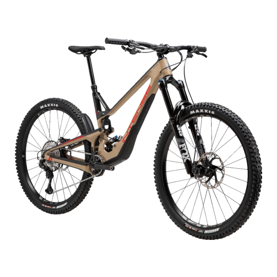
THE INTENSE TRACER Register your bike at: www.intensecycles.com/pages/registerbike The INTENSE Tracer Enduro bike has been completely redesigned for 2022. A brand new suspension configuration gives you 170mm (6.7”) of travel, a 29” front wheel and a 27.5” rear. Through extensive testing and racer feedback we have put... - Page 3 From the early days of INTENSE, when founder Jeff Steber worked alone in his garage, to today with our crew of talented people working in our Temecula, CA...
-
Page 4: Components
C Lower leg Front brake 05 Seatstay Rotor 06 Rear shock Spoke Saddle (seat) Tire Dropper seatpost Thru axle Seatpost clamp Model: INTENSE TRACER Model Year: 2022 Frame Travel: 170mm Compatible Forks: 170mm Headset: zs49/28.6 -ZS56/40 Seattube Diameter: 31.6mm BB Shell Width:... -
Page 5: Setup Guide
GO TO INTENSE.COM/PAGES/TECHVIDEOS WE ARE HERE TO HELP! If at any time you feel unsure about what you are doing then please contact us at INTENSE or seek the help of a professional mechanic at your local bike shop. INTENSE +1 951.307.9211... -
Page 6: Remove Wheels And
S T E P 1 REMOVE WHEELS & PUT BIKE IN STAND When you first open your bike box you will find an accessory/tool box and the bike itself. Carefully locate the tool box and remove the wheels from the bike box and put to one side. -
Page 7: Install Handlebars
S T E P 2 INSTALL HANDLEBARS Remove any packaging on the front of the bike, then spin the handlebar stem 180º so that the stem and forks are facing forward (A). Make sure that the forks are the correct way around – the front brake caliper should be on the left (non-drive) side of the bike, with the fork arch facing forward. - Page 8 S T E P 3 INSTALL SRAM REAR DERAILLEUR Move to the rear of the bike and cut off any zip-ties or packaging from the rear derailleur and chain. Using a 5mm Allen key, screw the derailleur into the derailleur hanger/frame (A). At this point be careful that the ‘B plate’...
- Page 9 S T E P 4 INSTALL REAR WHEEL Take out the rear brake pad spacer – this is usually orange, red or yellow plastic. Once removed be careful not to squeeze the brake lever until the rear wheel is in position.
- Page 10 S T E P 4 C O N T I N U E D . . . Once everything is lined up and in position, reinsert the axle and tighten using the integrated lever on the non-drive side (left), turning clockwise until tight (F). Reinstall the lever within the axle by pushing it firmly back in place.
- Page 11 S T E P 5 INSTALL FRONT WHEEL Remove all packaging from the front wheel making sure the hub end caps are still in the correct place and that they haven’t been pulled off by accident. If they do come off, just press them back into position. Then remove the brake pad spacer (usually orange, yellow or red) (B).
- Page 12 S T E P 6 INSTALL PEDALS Pedals are somewhat of a personal choice – some people prefer flat pedals, others clipless, and then of course there are all the different brands and designs. So please take note, your bike does not come supplied with pedals, so that you can choose your own.
- Page 13 S T E P 8 ADJUST HEADSET & HANDLEBARS Your bike’s headset comes ‘pre-loaded’ from our factory but it is good practice to check it. If it feels a little loose then undo the stem clamping bolts slightly using the Torx T25 tool and then gently tighten the top cap bolt using a 5mm Allen key to 2-4Nm.
- Page 14 S T E P 9 ADJUST SADDLE HEIGHT Set the height of your saddle (seat) with your seatpost in its fully extended position. Using a 5mm Allen key loosen the seatpost clamp and adjust the seatpost to the correct height. A good base measurement is to stand next to your bike in your riding shoes, putting your hand against the top of your hip bone (A).
- Page 15 TRACER 279 EXPERT Open (counterclockwise) The Tracer 279 Expert uses FOX air sprung suspension in the front fork and a coil Least amount of rebound spring on the rear. First you need to set the air pressure. Look at the air pressure damping.
- Page 16 S T E P 1 2 FRONT SUSPENSION SETUP TRACER 279 S The Tracer S uses Öhlins air sprung suspension in the front fork and a coil spring on the rear. First you need to set the air pressure of the fork. Look at the air pressure chart below (also to be found on the bottom of the right-hand fork leg) to calculate the air pressure you require.
- Page 17 S T E P 1 3 SETTING REAR SHOCK SAG REAR SUSPENSION SETUP TRACER 279 EXPERT The optimal sag on your rear shock is 30% of the piston’s movement inside the shock body (stroke). The distance between the two shock mounting bolts (eye- First check the spring rate-chart on the bottom of this page to make sure that the to-eye) without a rider on the bike is 205mm.
- Page 18 S T E P 1 3 SETTING REAR SHOCK SAG REAR SUSPENSION SETUP TRACER 279 S The optimal sag on your rear shock is 30% of the piston’s movement inside the shock body (stroke). The distance between the two shock mounting bolts (eye-to- First check the spring rate-chart on this page to make sure that the spring fitted on eye) without a rider on the bike is 205mm.
-
Page 19: Final Check
S T E P 1 4 FINAL CHECK You are almost ready to go riding. Now is a good time to check over your bike to make sure that everything looks correct – all packaging is removed, bolts are all tightened to the correct torques, etc. -
Page 20: The Flip Chip
Follow the steps below or check out the Tech Video for more details. The Flip Chip on the INTENSE Tracer 279 is located on the Lower Link of the suspension system where it bolts onto the rear shock. With the bike fully built... - Page 21 G E O M E T R Y FLIP CHIP... CONTINUED STEP 01 To remove the rear wheel shift the chain into the smallest gear on the cassette. Gently push your SRAM derailleur forward in a counterclockwise direction until it is vertical and then lock it in position using the ‘derailleur lock’...
- Page 22 G E O M E T R Y FLIP CHIP... CONTINUED STEP 04 Remove the two D-Lock Shoulder Bolts and pull the Top Link forward and carefully remove the silver spacers (F). STEP 05 In order for the Rear Triangle to move more freely pull the rear brake hose and rear derailleur cable through the frame by roughly 50mm/2”...
- Page 23 G E O M E T R Y FLIP CHIP... CONTINUED STEP 06 With a 5mm Allen key from the left (non-drive side) side loosen the Rear Shock Bolt (I). Once undone remove the Rear Shock Bolt by sliding it out (J). STEP 07 Remove your Flip Chips on both sides and flip them...
- Page 24 G E O M E T R Y FLIP CHIP... CONTINUED STEP 9 Now you need to reattach the Top Link. Make sure that the two Bearing Spacers are still in place (O). If they did dropout you can use a dab of grease here to help hold them in position.
- Page 25 G E O M E T R Y FLIP CHIP... CONTINUED STEP 13 Using a 5mm Allen key on the drive-side of the bike screw the D-Lock Nut onto the D-Lock Bolt (S). You’ll need to apply a little pressure on the end of the bolt on the left (non-drive side), just so that the bolt doesn’t get pushed out.
-
Page 26: The 'Chad System
I N T E R N A L S T O R A G E THE ‘CHAD SYSTEM’ Your INTENSE Tracer comes with a cool storage feature called the ‘CHAD System’, named after the late Chad Peterson, our former Product Manager, who developed the concept. -
Page 27: Geometry Charts
T R A C E R GEOMETRY CHARTS REACH SIZE LARGE (HI) SHOWN 77.9º 64.5º 1257 WHEELBASE HI SETTING LO SETTING SIZE SMALL MEDIUM LARGE EXTRA LARGE SIZE SMALL MEDIUM LARGE EXTRA LARGE WHEELBASE 1193MM / 47" 1228MM / 48.3" 1257MM / 49.5"... -
Page 28: Maintenance Schedule
CLEAN AND REGREASE INTERFACE WITH FRAME in any degree it’s best to have your frame FRAME PIVOTS REMOVE PIVOT BOLTS, CHECK BEARINGS FOR inspected by a qualified INTENSE, LLC PITTING AND WEAR dealer. Any direct impact to the frame can HEADSET DISASSEMBLE STEM, HEADSET AND FORK. -
Page 29: Parts Listings
T R A C E R 2 7 9 ITEM PART No. DESCRIPTION QTY. TORQUE SPEC. PARTS Bearing Cap 24mm OD 130765 Cap Bearing Blk Bearing Cap 130778 Cap Bearing Blk LISTING D-Lock Reducer 130803 Tracer RT D-Lock Reducer D-Lock Reducer 130805 Tracer Drive-Side RT Reducer Cone Adjuster... - Page 30 T R A C E R 2 7 9 ITEM PART No. DESCRIPTION QTY. TORQUE SPEC. PARTS 40 Hanger Hardware 410070 Hanger Stop, M4 x 8 x 10mm OD 2Nm / 18in-lbs 41 Rear Shock Bolt 410071 Bolt SHCS, M8 x 51, Rear Shock Bolt 16Nm / 140in-lbs LISTING CONT.
-
Page 31: Parts Kits
T R A C E R 2 7 9 PARTS KITS DOWNTUBE DOOR IT150144 Tracer Downtube Door 140070 Downtube Door Tracer 170000 Hook Velcro TOP LINK HARDWARE KIT IT150134 Top Link Hardware Kit Tracer 130813 Tracer RT D-Lock bolt 130803 Tracr RT D-Lock Reducer 130835 Cap Bearing Silver... - Page 32 Lower Link Flip Chip 130898 Lower Link M8 x 1.25 Thread, Flip Chip DERAILLEUR HANGER KIT IT150141 INTENSE Universal Derailleur Hanger (UDH) Kit 130897 Universal Derailleur Hanger (UDH) 410070 Hanger Stop, M4 x 8 x 10mm OD TOP LINK KIT...
-
Page 33: Torque Specifications
TORQUE SPECIFICATIONS Achieving correct torque is vital to ensuring the proper performance and function of the Tracer frame. Failure to do so could result in suboptimal performance of your frame as well as premature wear and tear of individual parts. In addition to this chart, torque values are laser etched onto corresponding hardware for your reference. - Page 34 20 22 / / T RACE R 2 7 9 E X P E R T & S MANUAL...
Need help?
Do you have a question about the TRACER 279 EXPERT and is the answer not in the manual?
Questions and answers