Table of Contents
Advertisement
Quick Links
Advertisement
Table of Contents

Summary of Contents for Vantage Hearth Vesper UAS
- Page 1 Vesper UAS Vision GCS Operator’s Manual v1.8...
-
Page 2: Table Of Contents
CONTENTS PAGE SYSTEM COMPONENTS & CONTROLS SAFETY A. FAILSAFE TRIGGERS B. EMERGENCY PROCEDURES C. LOW BATTERY D. LOSS OF GPS RC LOSS FAILSAFE LANDING LOCATION III. ENVIRONMENTAL CONDITIONS SETUP A. UNPACKING AND POWERING B. PAIRING C. PRE-FLIGHT CHECKLIST MANUAL FLIGHT A. - Page 3 A. GCS SETUP B. POWERING ON AND OFF C. PAIRING 1. INITIAL PAIRING 2. RE-PAIRING OR CHANGING BANDWIDTH 3. CONNECTING D. USER INTERFACE 1. VESPER STATUS ICONS ASSIGNING CONTROL BINDINGS GCS ANTENNAS VESPER HARDWARE A. ROTOR SETS B. TAKEOFF AND LANDING OPTIONS C.
-
Page 4: System Components & Controls
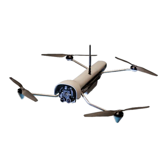
I. SYSTEM COMPONENTS & CONTROLS VESPER VISION GROUND CONTROL SYSTEM (VISION GCS) -
Page 5: Safety
II. SAFETY ● Read Vesper & Vision GCS Manual to completion before operating Vesper. ● Always ensure Vesper is at least 20 feet away from people before takeoff. ● Be mindful of where your hands and other body parts are, especially when Vesper is powered on. -
Page 6: Failsafe Triggers
FAILSAFE TRIGGERS & EMERGENCY PROCEDURES To program safe behavior for various scenarios: ● Click on the “Q” Ground Control logo on the top left-hand side ● Navigate to the Vehicle Setup menu at the top of the screen ● Select the Safety option The sections below detail how to program for specific situations:... -
Page 7: Low Battery
LOW BATTERY Vesper will automatically land and shut off once the battery level reaches 5%. The GCS will give multiple visual pop-up warnings in advance of the automatic landing. The operator can override the final 5% automatic landing with stick inputs, but should be aware that doing so risks loss of the aircraft. -
Page 8: Rc Loss
RADIO CONTROL (RC) LOSS Radio Control (RC) Loss means Vesper has lost connection to the Ground Control Station (GCS). In Q → Vehicle Setup → Safety, the operator can preemptively choose what actions Vesper will take should this scenario occur. By clicking the Failsafe Action dropdown menu, the operator can designate the best option for Vesper and determine how many seconds of data link loss will lead to time out. -
Page 9: Environmental Conditions
III. ENVIRONMENTAL CONDITIONS RANGE OF USE: ● Optimal flight conditions = open areas devoid of obstacles, crowds, power lines, trees, and bodies of water. ● To be field serviceable and to minimize dirt ingress, Vesper’s motors are partially sealed. Nonetheless, avoid contact with debris, sand and dirt whenever possible. -
Page 10: Setup
IV. SETUP IMPORTANT: READ SAFETY INSTRUCTIONS & ENTIRE MANUAL BEFORE FLYING VESPER UNPACKING AND POWERING 1. Remove Vesper from the field case and fully unfold all four arms. 2. Power on Vesper by grabbing battery on left and right sides; a beep, followed by a series of tones and illuminated tail LEDs indicate success. -
Page 11: Pairing
7. Once connection is established, place Vesper at chosen launch location. PAIRING 1. Power up Vesper and wait for the turquoise LED to switch to blue or green, indicating that boot is complete. 2. Pick up Vesper by the battery and flip Vesper upside down 3-4 times (flip from top to bottom and back) to initiate pairing. -
Page 13: Manual Flight
V. MANUAL FLIGHT Manual Mode allows the operator to have full control over Vesper’s path, using Vision GCS to direct all movement. You should only use Manual Mode if you are an experienced operator. When in Manual Mode ensure you are aware of your surroundings at all times, and whenever possible use the camera to view the flight direction. -
Page 14: Return To Launch Location (Rtl)
RETURN TO LAUNCH LOCATION (RTL) Command Vesper to return to the launch location by pressing the RTL button on Vision GCS. Vesper will respond by first ascending to 200 feet above takeoff altitude, or up to a cone extending up at 45° from the takeoff site, whichever is lower... -
Page 15: Automated Flight
VI. AUTOMATED FLIGHT Automated flight modes allow the operator to create a flight plan and have Vesper fly the entire route autonomously. Use-cases for Automated Flight Mode include: (a) rapidly flying to a predetermined location, (b) creating a photo dataset for 3D models, (c) creating a photo dataset for orthomosaics, and (d) automated search grids. - Page 16 3. Select Mission Mode. 4. Add waypoints * by selecting areas on the map. *Note: A waypoint is a point in three-dimensional space that the drone flies to as part of a mission. Each mission consists of a series of coordinated waypoints.
- Page 17 IMPORTANT : Set the first wappoint as close to the mission starting position as possible- this waypoint can mark the takeoff point. After plotting the route, the operator can set specific directions for Vesper at each waypoint, such as altitude, flight speed and camera. 5.
- Page 18 6. Set specific a ltitude directions for Vesper at each waypoint, as desired. By default, the altitude is set relative to home. The operator can change the altitude to be relative to sea level or relative to terrain.
- Page 19 7. Set the f light speed from the Mission Start position. ○ Operator MUST check the box next to “flight speed” and set the flight speed, otherwise Vesper will not proceed to the first waypoint upon takeoff.
- Page 20 8. From the mission sidebar, the operator may choose “Return to Launch” to automatically direct Vesper to return to the mission starting position. 9. Once waypoint(s) and additional directions are set, the operator can save the flight plan for future use by pressing the File button in the Plan menu.
- Page 21 10. The operator can see the Total Mission distance, time, and max range in the top information bar of QGC. The details are based on the chosen settings and directions and update in real time in response to the mission settings. 11.
- Page 22 USING FLIGHT PLAN FILES Flight Plans that have been created and saved, or loaded onto the GCS, are located in the Plan view under the File icon. Note: Flight Plan files are saved as “.plan” files.
- Page 23 CREATING A NEW FLIGHT PLAN FILE: 1. Under the File menu, select “New File” to create a new Flight Plan. 2. If there is already a Flight Plan open, a prompt will appear on the right side of the screen to ensure you want to remove any preselected commands.
- Page 24 LOADING A FLIGHT PLAN FILE: 1. Under the File menu, select “Open…” 2. A prompt will appear to open a Flight Plan file from storage.
- Page 25 3. If a Flight Plan is already open, a prompt will appear on the right side of the screen to ensure the operator wants to clear the existing file in order to open a new file. SAVING A FLIGHT PLAN FILE: 1.
-
Page 26: Flying A Mission Flight Plan
FLYING A MISSION FLIGHT PLAN 1. Once a flight path has been programmed and uploaded from the Plan view, navigate to the Fly view. A prompt to Start Mission will pop up at the bottom of the screen. Slide the blue arrow to confirm. -
Page 27: Returning Vesper After Flight
3. The Ground Control Station (GCS) will display Vesper on the map: ○ The red arrow indicates Vesper’s location. ○ The line indicates where Vesper has traveled. 4. If desired, the operator can make Vesper pause (suspended in the air) in its current location by using the control sticks on the GCS or by simply pressing the Pause button on the Fly menu. - Page 28 4. Vesper will then ascend and fly directly to the Mission Start location. ● Vesper will default to a 60 meter altitude for “Return to Launch” to ensure obstacle- and detection-avoidance. This pre-set altitude can be changed in Settings.
-
Page 29: Camera Control
VII. CAMERA CONTROL TAKE PHOTOS MANUALLY Note: s ee directions on Page 13 to automatically take photos on a mission. To take photos manually, touch the camera trigger (big circle) on the screen. The on-screen indicator will spin while photo capture is processing. SWITCH CAMERA MODES: ●... -
Page 30: Switch Sensors
SWITCH CAMERA SENSORS: ● Use button (19) on the GCS to toggle between Electro Optical (EO) and Thermal (LWIR) cameras. ● Alternatively,: ○ To select EO, tap the Icon on the right edge of the screen, above the camera control; or ○... -
Page 31: Zoom Control
● To stop recording, press the square icon. Camera controls for recording video: 1. Video/Photo control select 2. Record Start/Stop 3. Available storage space 4. Elapsed recording time Note: EO video recording continues even when switching to IR view mode (in which case both EO and IR streams are saved and available post flight). - Page 32 ● Zoom is achieved through a combination of optical and digital zoom. When capturing photos after zooming, photos are saved in the full resolution of the sensor and may appear less tightly zoomed than the view on the GCS. ● Zoom is only available on the optical cameras;...
-
Page 33: Post Flight
VIII. POST FLIGHT POWER DOWN ● Vesper will automatically shut off 5 minutes after the radio link is powered down. ● If the radio link to the GCS is active, Vesper will remain powered on until the battery is removed. POST-FLIGHT INSPECTION Inspection after every flight will help maintain Vesper and minimize safety risks. - Page 34 and with the antenna pointing up. ○ The gimbal faces outward when Vesper is in the field case correctly. TRANSFERRING VIDEOS Videos (and photos) may be stored to SD card or on the internal flash memory: ● If an SD card is installed, videos and photos will automatically be stored to it.
-
Page 35: Battery Usage And Charging
3. Access video downloads page. Open a web browser on your device. b. Navigate to "http://VantageUAS:5000" or alternatively "http://192.168.43.1:5000". Note: if access is through a Vantage GCS, there is a preloaded bookmark to this location. d. Upon loading, the Vesper download page will extract a few down-scaled frames and present them along with basic information for each video file. - Page 36 INSTALLING THE BATTERY: 1. Hold the battery in hand, touching both sides of the casing, with the magnets facing upward. 2. Verify a minimum of two green LEDs lit up, indicating the battery’s life is at least 50%. 3. Attach the battery to the underside of Vesper’s Fuselage: ●...
-
Page 37: Vision Ground Control Station
IX. VISION GROUND CONTROL STATION Vision Ground Control Station (GCS) controls Vesper while in flight. Vision GCS also programs flight paths, missions and functions. 1. Altitude/Yaw Joystick 2. Gimbal Pitch Joystick 3. Pitch/Roll Joystick 4. Return To Home 5. Camera Control 6. -
Page 38: Powering On And Off
POWERING ON & OFF 1. Press the Power button once to turn Vision GCS on. The Vantage Robotics logo will appear. b. Then the login screen will appear. 2. Login using the on-screen keyboard to type in default password “Vantage1”. 3. - Page 39 3. Click the PAIRING icon in the upper right of QGC. 4. A Discovering indicator will appear.
- Page 40 5. Tap the gear icon and ensure the pairing channel is set to 42 and the network ID is set to VANTAGE. These fields should already be set properly, this is just a troubleshooting step.
- Page 41 6. Flip Vesper, turning upside down, 3 times in a row consecutively. Vesper will play a tone to indicate that pairing mode has been triggered. 7. Once the Vesper is discovered, tap the Pair button to initiate the pairing process. 8.
- Page 42 9. To double check the connection, open the Pairing Manager and view the list of connected UAS (vehicles). ○ The name listed should match the name of the currently connected UAS, indicated on the upper left of the UI.
- Page 43 RE-PAIRING The operator can re-pair Vesper and Vision GCS or change the bandwidth by following the below steps: 1. Tap Pairing Manager. 2. Tap Disconnect. 3. Tap “Pair Another.” 4. Follow previous steps for pairing.
- Page 44 5. Change connection bandwidth, channel, and Tx Power in Settings -> Microhard. The default bandwidth is 4MHz. Do not select a bandwidth lower than 4 MHz. Connection channel can be changed to any available frequency other than the pairing channel (42). Note that there may be varying levels of interference on different channels.
-
Page 45: Connecting
CONNECTING: Once pairing steps have been completed, the operator should proceed with the following steps to connect Vesper and Vision GCS: 1. Power on Vesper and Vision GCS. 2. For 1.8 GHz units, ensure Vesper is at least 15 feet from Vision GCS (does not apply to 2.4GHz units). -
Page 46: Vesper Status Icons
Settings – configure the application Setup – configure and tune Vesper Plan – create pre-planned (autonomous) missions Fly – monitor Vesper while flying VESPER STATUS ICONS: Once Vesper is connected to Vision GCS, The Vesper status bar will show at the top of the screen. -
Page 47: Assigning Control Bindings
Vehicle messages – click to show a dropdown of messages. ● If there is a critical message, icon will change to a y ield sign ○ GPS Status – s atellite count, current Horizontal Dilution of ● Precision (HDOP) and other GPS information. - Page 48 2. Tap on the Joystick menu and then navigate to the Button Assignment tab. 3. Press a physical button on the GCS and see which button lights up in green on the Button Assignments page. 4. Use the dropdown menu next to the selected button to assign a function.
- Page 49 DISPLAYING MGRS COORDINATES INSTRUCTIONS FOR DISPLAYING MGRS COORDINATES: 1. Navigate to the “General” tab in the Application Settings menu and select “Display MGRS coordinates.” VISION GCS ANTENNAS The GCS has two antennas, Omni Antenna and Directional Antenna, that can be attached for different use cases: 1.
- Page 50 2. The Directional Antenna is foldable, wide and cone-shaped and is best for long distance and non-line-of-sight flight. ○ The Directional Antenna should be pointed directly towards Vesper for the most reliable signal. The operator can deploy the antenna by rotating the inner ring counter-clockwise with the palm of a hand.
- Page 51 NAVIGATING UBUNTU 1. Triple tap the menu bar to exit fullscreen mode in QGC. N ote: s creen below captures screen after fullscreen mode is exited.
- Page 52 2. To go full screen double tap top menu bar. 3. To exit QGC when not in fullscreen mode, tap the red X icon in the top right corner of the window..
- Page 53 4. To re-open QGC, double tap the QGC file on the desktop as shown below. Connecting to a Wifi Network. 1. Exit fullscreen mode by following instructions on p.48. 2. Tap the menu bar in the top right to access the quick settings menu.
- Page 54 3. Tap the Wifi icon to access the wifi quick settings menu. 4. Tap select network to show all available wifi networks.
- Page 55 5. Select the network you would like to connect to and enter the passphrase using the on-screen keyboard. Tap ‘Connect’ when done.
- Page 56 Accessing Ubuntu System Settings: 1. Tap the menu bar in the top right to access the quick settings menu.
- Page 57 2. Tap Settings to access Ubuntu System settings. We recommend that you do not change anything here as it may affect system performance. Disabling the lock screen: 1. Access the settings menu as shown above 2. Select Users in the Sidebar...
- Page 58 3. Tap Unlock in the top right corner of the screen. The authentication window will pop up. Enter the default password: Vantage1 4. Toggle the Automatic Login switch to disable the lockscreen on boot. 5. You can change the GCS password by selecting the Password Menu.
- Page 59 6. Enter the default password ‘Vantage1’ and then enter a new password. Tap Change to complete the change...
- Page 60 Accessing files: 1. Exit full screen mode by following the instructions above. 2. Tap the Folder icon in the dock on the left side to open the file browser.
-
Page 61: Vesper Hardware
X. VESPER HARDWARE ROTOR SETS Vesper has two rotor set options: the Safety Rotor Set and the Recon Rotor Set. Name Description Use for: ● Training, ● Flights near or Safety Rotor Set over people ● indoors / in other confined spaces. - Page 62 Never attempt hand launching Vesper when using the Recon Rotor Set INSTALLING THE RECON ROTOR SET: 1. Inspect the propellers for loose screws and damage. 2. Unfold the rotor arms so they are fully extended. 3. Confirm all magnets on Vesper’s fuselage and rotor set are free of sand and other debris.
-
Page 63: Takeoff And Landing Options
TAKEOFF AND LANDING OPTIONS Different takeoff and landing options can be used depending on the rotor set. RECON ROTOR SET CONFIGURATION: Ground Case Takeoff ( use field case as a takeoff platform) ● 1. Place the case lid side down, with the lid open, on a flat/level surface. - Page 64 ● Hand Takeoff Using Case: (use in rough terrain/moving platform) 1. Close the lid of the case. 2. Place the Vesper on top of the lid, aligning the magnets on the bottom of the battery to the magnets on the lid. 3.
- Page 65 ● Ground Takeoff: 1. When a flat surface is available Vesper can take off directly from the ground. 2. Always ensure blades have clearance to spin freely prior to takeoff. Note: g round takeoff mode is less desirable than the alternatives, since it increases the chance of dust/dirt getting on the camera lens.
- Page 66 CAMERA AND GIMBAL Vesper’s modular gimbal is equipped with (a) a low light, wide angle navigation camera, (b) a zoom camera and (c) a thermal camera. SENSOR SPECIFICATIONS: Lens Speed Horizontal FOV Resolution Navigation f1.0 63 degrees 3840x2160 Telephoto f2.4 17 degrees 3840x2160 Thermal...
-
Page 67: Field Case
TRANSPORTING VESPER VIsion GCS, Vesper, and Vesper accessories have customized cases and bags for storing and transporting properly. FIELD CASE: ● Store Vesper in the field case with the battery still attached by folding the Recon Rotor Set arms into the fuselage. ●... -
Page 68: Maintenance
XI. MAINTENANCE CLEANING & CARE ACCESSORY CASE The Vesper Cleaning & Care Accessory Case is a water resistant and contains: ● Set of four replacement propellers for the Recon Rotor Set and the Safety Rotor Set; ● Lens cleaning brush;uju ●... - Page 69 VESPER & VISION GCS CLEANING STEPS FOR CLEANING PARTS & SUBASSEMBLIES: 1. Preparation: Remove all components from the Field Case. b. Disassemble fuselage, battery and rotor set. 2. Battery: Remove any metal debris stuck to magnets. b. Recharge batteries with charging dock after use. Note: If a battery is cracked or otherwise unusable recycle it with other hazardous waste and replace it with a new battery.
-
Page 70: Replacing/Removing Gimbal
3. Rotor Set: Remove any metal debris stuck to magnets. b. Inspect the propellers for loose screws and damage. Confirm that all motors spin freely. 4. Fuselage: Clean the underside of the fuselage. b. Remove any metal debris stuck to magnets. 5. -
Page 71: Replacing Propellers
REPLACING PROPELLERS: ● Recon Rotor Set: 1. Gently pull the propeller directly off of the motor. 2. Replace with a new propeller. ■ The new propeller will snap into place easily; listen for a click sound. 3. Spin the blades with one finger to check that the new propeller is attached correctly;... - Page 72 ● Safety Rotor Set: 1. Remove the two screws attaching the propeller to the motor using a 1.5mm allen head screwdriver, turning screws counter-clockwise. 2. Set screws aside. 3. Ensure the new propeller is correct: for SRS → the white blades, and for RRS →...
- Page 73 5. The curves and direction of the slant must be the same as the previous blade used. B blades move counter-clockwise & A blades clockwise Note: When oriented as the picture below, the layout is: 7. Place the new propeller over the holes and attach with the screws.
-
Page 74: Troubleshooting
XII. TROUBLESHOOTING Common issues will be reported on the Vision GCS display as a warning/error message. For example, a lost or low link strength will result in a message displayed on the GCS, indicating that action should be taken. Below is a list of common issues, how to identify them, and troubleshooting steps to resolve them. - Page 75 4. If not successful, cancel pairing and try again. 5. If not successful, power cycle Vesper and repeat instructions. 6. If not successful, power cycle Vision GCS and repeat again. Pairing process High power 1. Confirm Vesper is on by checking gets stuck on transition the gimbal is active.
-
Page 76: Connecting
CONNECTING Problem Indicator Operator Response No telemetry No telemetry 1. Confirm that Vesper is on by or video or video checking that gimbal is active. appears after appears after 2. Confirm that the radio is plugged 60 seconds 60 seconds in correctly. -
Page 77: Pre-Flight
PRE-FLIGHT: Problem Indicator Operator Response (P) / Cooperator Response (C) Propeller(s) Propeller 1. (C) Check propellers for damage not rotating does not (i.e. cracks). freely make 2 2. (C) Check for obstruction (dirt, rotations sand, etc.) in the motor. when spun 3. - Page 78 attempts Gimbal is not Gimbal does 1. (C) Restart vesper while operating not maintain tilting/holding gimbal to the right properly level while (roll) of Vesper’s flight direction rotating the for 25 sec. After being released fuselage the gimbal will auto calibrate and return to level position.
-
Page 79: Flight
FLIGHT Problem Indicator Operator Response (P) / Cooperator Response (C) Lost “No Video” 1. (P) Confirm the antenna is pointing communication shown, in the correct direction. link telemetry stops 2. (P) Check antenna connections. updating Lost video “No Video” 1. (C/P) Confirm the antenna is stream shown, pointing in the correct direction. - Page 80 and Vesper >1km away Downed Vesper Unplanned 1. (P) Use the last known location on (LoS, BLoS) landing or the map to locate Vesper. Vesper brought 2. (P)/(C) Go to the search location down for Vesper recovery. Latency Slow video Early 1.
-
Page 81: Restarting Qgc
TAIL LED INDICATOR AND VEHICLE STATE REFERENCE Solid Pulsing Blinking Armed Ready Blue No GPS No GPS Armed Ready Green Turquoise Booting Failsafe Mode Purple (vehicle will RTL or land) Amber Low Battery Error, Critical Low Battery RESTARTING QGC: 1. Tap the top of the QGC window three times to make the window smaller.
Need help?
Do you have a question about the Vesper UAS and is the answer not in the manual?
Questions and answers