JVC VN-V25U VN-V26U Instructions Manual
Ip camera
Hide thumbs
Also See for VN-V25U VN-V26U:
- Instructions manual (92 pages) ,
- Specifications (4 pages) ,
- Quick start manual (2 pages)

Related Manuals for JVC VN-V25U VN-V26U


Summary of Contents for JVC VN-V25U VN-V26U
- Page 1 IP CAMERA VN-V25U VN-V26U VN-V25U INSTRUCTIONS VN-V26U Thank you for purchasing this JVC product. Before operating this unit, please read the instructions carefully to ensure the best possible performance. LST0674-001A...
-
Page 2: Getting Started
If you wish to dispose of this product, please visit our web page Union. www.jvc-europe.com to obtain information about the take-back of the product. [Other Countries outside the European Union] If you wish to dispose of this product, please do so in accordance with applicable national legislation or other rules in your country for the treatment of old electrical and electronic equipment. - Page 3 This apparatus is in conformance with the valid European directives and standards regarding electromagnetic compatibility and electrical safety. European representative of Victor Company of Japan, Limited is: JVC Technology Centre Europe GmbH Company name changed in: JVC Technical Services Europe GmbH...
-
Page 4: Important Safeguards
Getting Started These are general IMPORTANT SAFEGUARDS and certain items may not apply to all appliances. 1. Read all of these instructions. 2. Save these instructions for later use. 3. All warnings on the product and in the operating instructions should be adhered to. 4. -
Page 5: Table Of Contents
Contents Getting Started ... 2 Safety Precautions ... 2 Main Features ... 6 Operating Environment ... 7 Cautionary Notes ... 8 Name and Function of Parts ... 10 Front / Bottom / Side ... 10 Side ... 11 Rear ... 12 Features ... -
Page 6: Main Features
Getting Started Main Features High Picture Quality The camera unit of this product employs a 330,000-pixel CCD (1/4") which enables high quality video surveillance. Support for Dual Stream Simultaneous distribution of JPEG and MPEG4 images is possible. Realization of Full Frame Rate Data transmission is possible in VGA size at a rate of 30 fps. -
Page 7: Operating Environment
VN-V25U and VN-V26U are indicated as VN-V25U. Content of this manual ● All rights reserved by JVC. Unauthorized duplication or reprinting of this manual, in whole or in part, is strictly prohibited. ● Windows is a registered trademark of Microsoft Corporation in the U.S. -
Page 8: Cautionary Notes
Exemption of Liability The motion detection feature is not a feature to prevent theft or fire. JVC shall not be liable for any damage that occurs. JVC shall not be liable for any damage due to the invasion of privacy by images of this camera. - Page 9 If a high luminance object (such as a lamp) is shot, a white smear may appear at the upper and lower ends of this object on the screen. This phenomenon (smear) is characteristic of solid-state image sensors, and is not a malfunction.
-
Page 10: Name And Function Of Parts
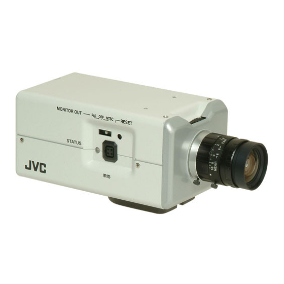
Getting Started Name and Function of Parts Front / Bottom / Side The model illustrated in the diagram is VN-V26U. Back Focus Adjustment Ring This ring is used for back focus adjustment and switching the lens mount method. To operate, loosen the I back focus fastening screw by turning it in the anti-clockwise direction, and turn the screw in the clockwise direction to fasten after operation is complete. -
Page 11: Side
Side [MONITOR OUT] Monitor Output Selection Switch Use this switch to select the availability of output from the O [MONITOR OUT] terminal as well as the signal system. NTSC : Outputs NTSC signals. : No output. Select this value when distributing images to the network. -
Page 12: Rear
Getting Started Rear VN-V25U AC24V MONITOR 10BASE-T/ SEE INSTRUCTION MANUAL 100BASE-TX CAUTION AC 24V : NEVER USE AT THE SAME TIME DO NOT CONNECT TO THE TELEPHONE NETWORK [MONITOR OUT] Monitor Video Signal Output Terminal (RCA) This is an output terminal for composite video signals (1 V (p-p), output impedance of 75 K). -
Page 13: Features
Features Surveillance Using the Built-in Viewer VN-V25U/26U comes with a built-in ActiveX JPEG Viewer and MPEG4 Viewer. JPEG images and MPEG4 images of VN-V25U/26U can be monitored using the computer by installing this built-in viewer on the computer. JPEG images that are currently displayed can also be captured in the computer’s hard disk. - Page 14 Getting Started Sending audio to the network (VN-V26U only) Sends out audio picked up using the built-in microphone of VN-V26U to computers. VN-V26U MAC address Built-in mike Network Receiving and outputting audio from the computer via the network (VN-V26U only) Receives audio that is input to a computer, and outputs the audio to a speaker that is connected to [AUDIO OUT] terminal of VN-V26U.
-
Page 15: Setup Procedures
Setup Procedures Step 1 Connection/Installation (A Page 17) Connect the lens mount, power supply cord, LAN cable and alarm. Next, mount the camera to the ceiling. Remember also to mount the fall prevention wire. After the camera is mounted, connect the video monitor to the [MONITOR OUT] terminal at the rear of the unit, followed by adjusting the camera angle. -
Page 16: Connection / Installation
Connection / Installation Mounting the Lens Check the mounting method of the lens to be used before mounting ● The default method used for this camera is CS mount. To use a C mount lens, loosen the back focus fastening screw using a screwdriver, followed by turning the back focus adjustment ring using a finger or pointed object (e.g., screwdriver, etc.) to... -
Page 17: Power Connection
Power Connection Electricity can be supplied to this product either by connecting to the AC 24 V power supply or using the PoE (A Page 18). When power is supplied to this product, the [STATUS] indicator at the side lights up. The indicator lights up in orange color during startup, and switches to green color after startup is complete. -
Page 18: Using The Poe
Connection / Installation ● In a system where multiple units of VN-V25U/ 26U are used, turn on the power of only one unit to configure the IP address settings using the Internet Explorer. Upon doing so, turn on the power of the second unit and configure accordingly. -
Page 19: Lan Cable Connection
LAN Cable Connection Connect the camera to a hub or computer using a LAN cable. Cable to use ● Shielded cable ● Length of 100 m or shorter When connecting to a hub Make use of a straight cable. When connecting to a computer Make use of a cross cable. -
Page 20: Alarm Input/Output Terminal Connection
Connection / Installation Alarm Input/Output Terminal Connection Connect the alarm input/output terminals with external devices, such as a sensor or buzzer. Plug/Unplug the cable while pressing the button as shown in the diagram below. Cable to use ● Shielded cable ●... -
Page 21: Mounting The Camera
Mounting the Camera Use the screw hole on the camera mounting bracket to mount this camera to a fixer or rotating platform. Camera Mounting Camera Mounting Screw Hole Bracket Fastening Screw 1/4-20UNC (2 pcs: M2.6 x 6 mm) Anti-rotation Hole Mounting the camera mounting bracket on the top of the camera Caution:... -
Page 22: Mounting To The Housing Using The Inner Tripod Base
Connection / Installation Warning ● Special attention is required when mounting the camera to a wall or ceiling. Users should get professional contractors to perform mounting operations instead of doing it themselves. Failure to do so may cause the camera to fall off and result in injuries or accidents. -
Page 23: Back Focus Adjustment
Inner Tripod Base Mounting Screw Make use of 1/4-20UNC screw. The length of the mounting screw shall be between 6 mm to 7 mm from the mounting surface. Caution: ● Using a screw with a length longer than specified may damage the internal parts of the camera, while using a length shorter than specified may cause the camera to fall off. -
Page 24: Network Requirements
Connection / Installation Network Requirements ● Ensure that there is sufficient network bandwidth for the data volume to be sent out by VN-V25U/26U. Do not send multicast stream that exceeds the bandwidth. If the entire bandwidth is used by the multicast stream, control of this camera via the network may fail. - Page 25 Restrictions on the Number of Distributions for VN-V25U/26U The maximum number of distributions for VN-V25U/26U is determined by the settings as well as requirements from the client. When only JPEG images are distributed, the maximum number of distributions is determined based on the highest bit rate within the stream.
- Page 26 Connection / Installation Network Requirements (continued) List of Protocols and Port Numbers Used by VN-V25U/26U VN-V25U/26U uses the protocols and port numbers listed below. Ensure that these ports are allowed through the firewall when a firewall is to be installed. Protocol/Port No.
-
Page 27: Network Settings
Network Settings IP Address Settings Setting the IP address for VN-V25U/26U There are two methods to set the IP address for VN-V25U/26U as follows. (A) Assigning an IP address to VN-V25U/26U from the DHCP server (B) Assigning a static IP address to VN-V25U/ (A) Assigning an IP address from the DHCP server ●... - Page 28 Network Settings IP Address Settings (continued) IP address setting at the computer Set the computer to an IP address that enables communication with VN-V25U/26U. Click [Start] ● Select in the sequence of [Control Panel]-[Network Connection]-[Local Area]. The computer on which Internet Explorer is launched automatically selects the connected network ●...
- Page 29 Changing the IP address using the Internet Explorer Launch the Internet Explorer on the computer When proxy settings are enabled in the Internet Explorer, follow the steps below to disable the proxy of the Internet Explorer ● Select in the order of [Tool]-[Internet Options]-[Connections]-[LAN Setting], followed by deselecting the check for [Use a proxy server for your LAN] under [Proxy Server] of the [Local Area Network (LAN) Settings] window.
- Page 30 Network Settings IP Address Settings (continued) Changing the IP address using the Internet Explorer (continued) Launch the Internet Explorer Enter the following IP address into the address field. http://192.168.0.2 Note: ● If the proxy server settings for access to the Internet via the Internet Explorer is enabled, you may not be able to specify the IP address directly.
- Page 31 The top page of VN-V25U/26U appears The [Basic] page with the IP address settings appears when DHCP is not in use A confirmation screen appears. Press the [OK] button. VN-V25U/26U restarts using the new IP address. It takes about one minute for the camera to reboot. Note: ●...
-
Page 32: When The Ip Address Of Vn-V25U/26U Is Known
Network Settings IP Address Settings (continued) When the IP address of VN-V25U/26U is known When the IP address of VN-V25U/26U is known, it can be changed by accessing the built-in web page of VN-V25U/26U via the Internet Explorer on the computer. Refer to ASetting Using Internet ExplorerB (A Page 33). -
Page 33: Setting Using Internet Explorer
Setting Using Internet Explorer Setup Internet Explorer Setup Launch the Internet Explorer on the computer When proxy settings are enabled in the Internet Explorer, follow the steps below to disable the proxy of the Internet Explorer ● Select in the order of [Tool]-[Internet Options]-[Connections]-[LAN Setting], followed by deselecting the check for [Use a proxy server for your LAN] in [Proxy Server] of the [Local Area Network (LAN) Settings] window. -
Page 34: Enter User Name And Password
Setting Using Internet Explorer Setup (continued) Disable pop-up block Connection of VN-V25U/26U cannot be established when pop-up block in the Internet Explorer is set to AEnableB. Follow the steps below to set the pop-up block to AdisableB. ● Selecting [Tool]-[Pop-up Blocker]-[Turn Off Pop-up Blocker] permits all sites. - Page 35 ● operator Image [View] [Camera] [Encoding] [Audio] (VN-V26U only) External [Alarm] [Alarm Environment] [Privacy Mask] [Motion Detection] Network [Streaming] Utility [LED State] [Miscellaneous] Status [Operation] [Settings] ● user Image [View] Utility [Miscellaneous] Note: ● The [Security Settings] screen appears before the top page is displayed. Press the [Yes] button to proceed.
-
Page 36: Setting
Setting Using Internet Explorer Setting View Page This top page is displayed upon access using any of the user names AadminB, AoperatorB or AuserB. The camera image is displayed as a still image. Links to each page are found at the left end. The links displayed vary according to the user name. For example, in the case of AadminB or AoperatorB, three links, namely [View], [Camera] and [Encoding] are displayed upon clicking [Image]. - Page 37 Reload Still Press this button to refresh the displayed still image. Clicking [View] or re-entering the Internet Explorer address will only display the Image page that is temporarily stored in the Internet Explorer, and still images may not be refreshed. To refresh still images using the above operations, change the Internet Explorer settings as follows.
-
Page 38: Camera Page
Setting Using Internet Explorer Setting (continued) Camera Page This page is for setting the camera’s parameters. This page can be used during access using AadminB or AoperatorB. ● Press the [OK] button to enable the new settings. ● If the [OK] button is pressed upon entering an invalid value, a warning message will appear and the entry will be denied. - Page 39 Camera ID Character strings entered here will be written to the JPEG comment segment (item name: camera). Refer to the API Guide on the file formats of JPEG. Monitor Type For selecting the monitor type according to the monitor used to display the video images.
- Page 40 Setting Using Internet Explorer Setting (continued) Camera Page (continued) For setting the AGC (automatic gain control) level. High Super [Set values: Off, Mid, High, Super] Note: ● This feature cannot be configured when the [Easy Day and Night] is set to AOnB.
- Page 41 Shutter Speed For setting the shutter speed. Auto 1/30 ~ 1/10000 Flickerless [Set values: Auto, 1/30, 1/50, 1/60, 1/100, 1/250, 1/500, 1/1000, 1/2000, 1/4000, 1/10000, Flickerless] Note: ● AAutoB is only recommended when using a manual iris lens. ● Flickers may occur when this is set to a value other than A1/50B, A1/100B, or AFlickerlessB.
- Page 42 Setting Using Internet Explorer Setting (continued) Camera Page (continued)
- Page 43 White Balance For selecting the white balance control feature. White balance can be adjusted for a light source with a color temperature range of 2800K to 9500K. Switches to the Auto-Tracking White Balance (automatic color temperature tracking) mode. Adjusts the white balance automatically according to the color temperature of the light.
-
Page 44: Encoding Page
Setting Using Internet Explorer Setting (continued) Encoding Page This page is for setting JPEG and MPEG4 encoding parameters. This page can be used during access using AadminB or AoperatorB. ● Press the [OK] button to enable the new settings. ● If the [OK] button is pressed upon entering an invalid value, a warning message will appear and the entry will be denied. - Page 45 JPEG Quality/Size For specifying the rate control mode and target file size for JPEG. When AVFS1B to AVFS7B is selected, the quantization table during JPEG encoding will be maintained and the file size will increase/decrease according to the input signals. Stipulated values will be displayed in the Size field.
-
Page 46: Audio Page (Vn-V26U Only)
Setting Using Internet Explorer Setting (continued) Audio Page ( VN-V26U only) This page is for setting the audio parameters. This page can be used during access using AadminB or AoperatorB ● To enable the new settings, press the [OK] button. Duplex Mode For setting the audio transmission method. -
Page 47: Alarm Page
Alarm Page This page is for setting actions when there is an alarm. Up to 5 actions (No. 01 - No. 05) may be set. This page can be used during access using AadminB or AoperatorB. ● Press the [OK] button to enable the new settings. Only items that are valid under the selected action will be saved. - Page 48 Setting Using Internet Explorer Setting (continued) Alarm Page (continued) Action For specifying the type of action. Disable Mail TCP/UDP Data : Input up to 127 alphanumeric characters. Output 1 Make Output 2 Make Output 1 Break Output 2 Break For VN-V26U, you can specify the following items in addition to the above. BlackWhite B Color Color B BlackWhite Auto Low...
- Page 49 1st Trigger For specifying the first trigger to be activated. Either alarm input (make), alarm input (break) or motion detection can be selected. For VN-V26U, you can specify the following items in addition to the above. BlackWhite B Color Color B BlackWhite Note: ●...
- Page 50 Setting Using Internet Explorer Setting (continued) Alarm Page (continued)
- Page 51 Mail Mail Address Mail Text Attach Image TCP/UDP TCP/UDP IP Address TCP/UDP Port Number TCP/UDP Data Alarm Output For setting the alarm output time from the alarm output terminal. When this is set to “0”, it is not possible to revert back to break (or make) Duration after changing to make (or break).
-
Page 52: Alarm Environment Page
Setting Using Internet Explorer Setting (continued) Alarm Environment Page This page is for setting alarm-related environments. This page can be used during access using AadminB or AoperatorB. ● Press the [OK] button to enable the new settings. ● If the [OK] button is pressed upon entering an invalid value, a warning message will appear and the entry will be denied. - Page 53 Mail For setting the mail environment when [Mail] is specified as an action on the Alarm page. [SMTP] and [POP] can be used. Configure only the [SMTP] settings under usual circumstances. Enter the camera’s mail address as the recipient’s mail address. Configure the [POP] settings as well if [POP before SMTP] is enabled.
- Page 54 Setting Using Internet Explorer Setting (continued) Alarm Environment Page (continued)
- Page 55 Time Filter: For specifying the periodic FTP transfer action with respect to each day of the week and setting the corresponding time of the day. Applicable day of week : Sunday, Monday, Tuesday, Wednesday, Alarm action Applicable time period : For specifying the start and end time in hours and Pre-/Post-recording parameter: [PrePostRecording Frame Rate] [PrePostRecording Before Trigger] : For setting the FTP pre-recording...
-
Page 56: Privacy Mask Page
Setting Using Internet Explorer Setting (continued) Privacy Mask Page Privacy Mask is a feature that enables masking of a portion of the image. VN-V25U/26U enables privacy masks to be specified in different shapes. The Privacy Mask masks area by uploading a BMP file painted in red (created separately). The displayed color is determined by the color specified on this page. - Page 57 Mode For specifying whether to activate the Privacy Mask feature. When this is set to AOnB, the privacy mask specified using the following items will appear on the image. Note: ● When MPEG4 is set to the same frame size as JPEG, privacy masks are displayed on both images.
-
Page 58: Motion Detection Page
Setting Using Internet Explorer Setting (continued) Motion Detection Page This page is for setting motion detection. ● The area valid for motion detection is displayed in blue. ● The area where motion is detected is displayed in red. - Page 59 Display Screen The screen is divided into blocks of 10 (horizontal) x 8 (vertical). Use this to set whether to mask each block. All blocks are masked in the default setting. The block turns blue when it is clicked, indicating that it is unmasked. Click again to return to the masked state.
-
Page 60: Basic Page
Setting Using Internet Explorer Setting (continued) Basic Page This page is for performing basic setting related to the network. This page can be used during access using AadminB. ● Press the [OK] button to enable the new settings. ● If the [OK] button is pressed upon entering an invalid value, a warning message will appear and the entry will be denied. - Page 61 IP Setting For setting the DHCP client function. Connect VN-V25U/26U to a network environment with a DHCP server when DHCP is to be enabled. If the DHCP server does not exist when DHCP is set to AEnableB, VN-V25U/ 26U will start running with the 192.168.0.2 IP address and 255.255.255.0 subnet mask in about 2 minutes after startup.
-
Page 62: Details Page
Setting Using Internet Explorer Setting (continued) Details Page This page is for performing detailed network setting. This page can be used during access using AadminB. ● Press the [OK] button to enable the new settings. ● If the [OK] button is pressed upon entering an invalid value, a warning message will appear and the entry will be denied. -
Page 63: Protocol Page
Protocol Page This page is for changing the HTTP server port number. This page can be used during access using AadminB. ● Press the [OK] button to enable the new settings. ● After changing, you will need to re-establish the connection if you are using the Internet Explorer. HTTP Server You can change the port number for the built-in web server of VN-V25U/26U. -
Page 64: Streaming Page
Setting Using Internet Explorer Setting (continued) Streaming Page This page is for setting manual multicast transmission. This page can be used during access using AadminB or AoperatorB. ● Press the [OK] button to enable the new settings. ● If the [OK] button is pressed upon entering an invalid value, a warning message will appear and the entry will be denied. - Page 65 JPEG Control For starting or stopping streaming of JPEG images. Parameters that are set on the [Streaming] page will be saved when transmission is started upon pressing the [Start] button. Destination For specifying the destination address of JPEG streaming. Specify the multicast address. When other devices that make use of Address multicast transmission exist, ensure that each of them is set to a different multicast address.
-
Page 66: Access Restrictions Page
Setting Using Internet Explorer Setting (continued) Access Restrictions Page This page is for setting client restrictions. This page can be used during access using AadminB. ● Press the [OK] button to enable the new settings. ● If the [OK] button is pressed upon entering an invalid value, a warning message will appear and the entry will be denied. - Page 67 Destination Address Restrictions may be imposed on clients accessing VN-V25U/26U using the IP address. Access When AdenyB is selected, acquisition of JPEG/MPEG4 via the IP address specified for the [IP Address] item will be denied. Restrictions are not Restrictions imposed on access to the Web Settings page. When AallowB is selected, acquisition of JPEG/MPEG4 via the IP address specified for the [IP Address] item will be permitted.
-
Page 68: Time Page
Setting Using Internet Explorer Setting (continued) Time Page This page is for setting time. This page can be used during access using AadminB. ● Press the [OK] button to enable the new settings. ● If the [OK] button is pressed upon entering an invalid value, a warning message will appear and the entry will be denied. -
Page 69: Password Page
VN-V25U/26U is case sensitive. New Password Enter again to confirm the new password. Again Caution: ● Be sure to handle the password carefully in case you forget it. ● In the event that you forget the password, please consult JVC’s servicing center. -
Page 70: Maintenance Page
Setting Using Internet Explorer Setting (continued) Maintenance Page This page is for maintenance purposes. This page can be used during access using AadminB. All Settings Restores all settings to their default values and reboots the unit. (It takes about one minute for the camera to initialize and reboot.) AInitializeB Passwords will also be initialized. -
Page 71: Led State Page
LED State Page This page is for setting the method for lighting the [STATUS] indicator at the side of VN-V25U/26U. This page can be used during access using AadminB or AoperatorB. ● Press the [OK] button to enable the new settings. LED State For selecting whether to light up the [STATUS] indicator of this unit when it is running. -
Page 72: List Of Factory Settings Of Each Page
Setting Using Internet Explorer Setting (continued) List of Factory Settings of Each Page Camera Page Item Camera ID Monitor Type Black Level Gamma Enhance Frequency Enhance Level Color Level Sense Up ALC Priority Shutter Speed Easy Day and Night (VN-V25U only) B&W Mode (VN-V26U only) EV Compensation... - Page 73 List of Factory Settings of Each Page (continued) Privacy Mask Page Item Mode Masking Color Setting Motion Detection Page Item Mask Detection Level Basic Page Item IP Setting DHCP Enable IP Address 192.168.0.2 Subnet Mask 255.255.255.0 Default Gateway 0.0.0.0 Host Name —...
-
Page 74: Miscellaneous Page
Setting Using Internet Explorer Setting (continued) Miscellaneous Page This page is for acquiring information. This page can be used during access using AadminB, AoperatorB and AuserB. Open Source Press the [Show] button to display information of the software used by VN-V25U/26U. -
Page 75: Operation Page
Operation Page Displays the operating status of VN-V25U/26U. This page can be used during access using AadminB or AoperatorB. Total Sending Displays the total TCP/UDP bit rate sent by VN-V25U/26U as well as the individual bit rates. Bitrate Destination Displays the destination that VN-V25U/26U is sending data to. System Log Displays the following information. -
Page 76: Settings Page
Setting Using Internet Explorer Settings Page This page displays the version information and settings of VN-V25U/26U. This page can be used during access using AadminB or AoperatorB. - Page 77 Settings Page (continued)
- Page 78 Setting Using Internet Explorer Setting (continued) Settings Page (continued)
-
Page 79: Operation
Operation Operation of Built-in Viewer This product comes with a JPEG Viewer and an MPEG4 Viewer. Each of these viewers functions separately. Using the JPEG Viewer enables display of a series of still images as well as one-shot recording of still images. - Page 80 Operation Operation of Built-in Viewer (continued) Internet Explorer Setup (continued) If ActiveX controls and plug-ins of the Internet Explorer is disabled, follow the steps below to enable it ● Click [Trusted sites] under [Tool]-[Internet Options]-[Security]. Upon doing so, the [Sites…] button directly below becomes active.
-
Page 81: Installing The Built-In Viewer
Installing the built-in viewer Enter the URL of the built-in viewer in the address field of Internet Explorer For example, if the IP address of VN-V25U/26U is 192.168.0.2, enter as follows: VN-V25U ● JPEG Viewer http://192.168.0.2/cgi-bin/v25viewing.cgi?v25monitor_j.html ● MPEG4 Viewer http://192.168.0.2/cgi-bin/v25viewing.cgi?v25monitor_m.html VN-V26U ●... -
Page 82: Screen Configuration Of Jpeg Viewer
Operation Operation of Built-in Viewer (continued) Screen Configuration of JPEG Viewer ● When the JPEG Viewer is first installed, it is set to play back at 15 fps by default. VN-V25U ■ VN-V26U... - Page 83 DisplaySize Switches the display size. (VGA or QVGA) Capture Captures the currently displayed image on the computer. Images captured will be stored as a JPEG file in the folder created under [My Document] of the computer. The default folder names for VN-V25U and VN-V26U are AVN-V25UB and AVN-V26UB respectively.
-
Page 84: Jpeg Viewer Configuration
Operation Operation of Built-in Viewer (continued) JPEG Viewer Configuration The viewer setting window appears upon clicking the [Setup] button of the built-in viewer. - Page 85 On Screen Display For setting display items on the viewer screen. For the JPEG Viewer, characters are displayed as overlay on the video Settings image. Camera ID Select AOnB to display [Camera ID]. [Camera ID] can be specified on the [Camera] page of VN-V25U/26U. (A Page 39) Selecting AOnB displays the area in which motion is detected in red.
- Page 86 Operation Operation of Built-in Viewer (continued) JPEG Viewer Configuration (continued) Multicast IP Address Multicast Port Folder Name Cancel Note: ● The settings of the built-in viewer are stored in the file named Cookie. This setting screen is used to set the built-in viewer as a software on the computer, and does not apply to settings of the VN-V25U/ 26U unit.
-
Page 87: Exiting The Jpeg Viewer
Exiting the JPEG Viewer To exit, press the [close] button at the top right of the window. ● During the next startup of the built-in viewer, launch the Internet Explorer and enter the URL of the built-in viewer in the address field. For example, if the IP address of VN-V25U/26U is 192.168.0.2, enter as follows: VN-V25U http://192.168.0.2/cgi-bin/v25viewing.cgi?v25monitor_j.html... -
Page 88: Screen Configuration Of Mpeg4 Viewer
Operation Operation of Built-in Viewer (continued) Screen Configuration of MPEG4 Viewer VN-V25U ■ VN-V26U... - Page 89 DisplaySize Pause Setup Speech (VN-V26U only) Audio Setup (VN-V26U only) Note: ● To use the built-in MPEG4 Viewer of VN-V25U/26U, install “ffdshow” that is open source codec. You can download “ffdshow” from the Internet. Switches the display size. (VGA or QVGA) Pauses/Resumes playback of motion images.
-
Page 90: Mpeg4 Viewer Configuration
Operation Operation of Built-in Viewer (continued) MPEG4 Viewer Configuration The MPEG4 Viewer’s settings window appears upon clicking the [Setup] button of the viewer. Title Bar Display Settings Camera ID Time Format For setting display items on the viewer screen. For the MPEG4 Viewer, characters are displayed in the title bar of the window. - Page 91 Stream Settings Stream HTTP Port Multicast IP Address Multicast Port Cancel Note: ● To use the built-in MPEG4 Viewer of VN-V25U/26U, install “ffdshow” that is open source codec. You can download “ffdshow” from the Internet. For specifying settings for receiving MPEG4 stream. For selecting the protocol when the viewer acquires data from VN-V25U/26U.
- Page 92 Operation Operation of Built-in Viewer (continued) Note: ● The settings of the built-in viewer are stored in the file named Cookie. This setting screen is used to set the built-in viewer as a software on the computer, and does not apply to settings of the VN-V25U/ 26U unit.
-
Page 93: Exiting The Mpeg4 Viewer
Exiting the MPEG4 Viewer To exit, press the [close] button at the top right of the window. ● During the next startup of the built-in viewer, launch the Internet Explorer and enter the URL of the built-in viewer in the address field. For example, if the IP address of VN-V25U/26U is 192.168.0.2, enter as follows: VN-V25U http://192.168.0.2/cgi-bin/v25viewing.cgi?v25monitor_m.html... -
Page 94: Audio Setup (Vn-V26U Only)
Operation Operation of Built-in Viewer (continued) Audio Setup (VN-V26U only) Click the [Audio Setup] button of the built-in viewer to display the audio settings window. - Page 95 Receive Setup Receive Stream Multicast IP Address Multicast Port Speech Setup Destination Port Operator password HTTP Port Cancel Note: ● Settings of the built-in-viewer are stored in the file named Cookie. For specifying settings related to receiving of audio sent from VN-V26U. For specifying whether to receive audio.
-
Page 96: Shortcut For Built-In Viewer
Operation Operation of Built-in Viewer (continued) Shortcut for Built-in Viewer Creating a shortcut for the built-in viewer on the Desktop screen of the computer saves you the trouble of having to enter the URL in the Internet Explorer. Create the shortcut by following the procedure below. -
Page 97: Others
Others Troubleshooting Symptom IP address of VN-V25U/26U is unknown The web page of VN-V25U/ 26U cannot be displayed The built-in viewer cannot be installed Authentication by Verisign appears during installation of the built-in viewer A warning message appears upon starting up the built-in viewer TCP images cannot be played back... - Page 98 Others Troubleshooting (continued) Symptom Multicast images cannot be played back The frame rate of the displayed image is low A white zone appears in the built-in viewer Unable to receive alarm notification using the computer via TCP/UDP Images are not distributed to the network Causes and Countermeasures ●...
- Page 99 Symptom The MPEG4 Viewer screen appears in black No MONITOR OUT image output Zonal noise occurs at the bottom of the MONITOR OUT image Images from the network are distorted Causes and Countermeasures When DirectX 9.x or Windows Media Player 9.x is installed on the computer, the video image screen appears in black.
-
Page 100: Specifications
Others Specifications Camera Unit Pick-up element : 1/4-inch progressive scan Effective pixels : Approx. 330,000 pixels 659 (H) Lens Mount : C/CS mount [Monitor Output] Composite video x 1 (75 K, 1 Vp-p) Minimum object illumination: (VN-V25U) : 1.0 lx (50 %, F1.2, AGC Super) : 0.5 lx (25 %, F1.2, AGC Super) - Page 101 Ambient humidity : 20 % RH _ 85 % RH (without condensation) Mass : 480g (1.06 lbs) (VN-V25U) : 530g (1.17 lbs) (VN-V26U) Accessories/Attachments : Start-up Guide ... 1 CD-ROM ... 1 Warranty Card (For USA)... 1 Service Information Card (For USA) ...
-
Page 102: Dimension
Others Dimension [Unit: mm (inch)] VN-V25U VN-V26U T Specifications and appearance of this product are subject to changes for improvement without prior notice. U1-32 65 (2-9/16) BF LOCK 42 (1-5/8) 66 (2-5/8) 30 (1-3/16) U1-32 65 (2-9/16) BF LOCK 42 (1-5/8) 66 (2-5/8) 30 (1-3/16) 126 (5) - Page 104 LST0674-001A © 2008 Victor Company of Japan, Limited...