Table of Contents
Advertisement
Advertisement
Table of Contents

Related Manuals for Trumpf TruSystem 7000


Summary of Contents for Trumpf TruSystem 7000
- Page 1 TruSystem 7000 Operating Table Service Manual...
- Page 2 Reprinting, copying or translating this document, in whole or in part, is forbidden without the express written permission of TRUMPF Medizin Systeme GmbH + Co. KG. TRUMPF Medizin Systeme GmbH + Co. KG expressly reserves all rights under copyright law. Within the bounds of the legal requirements, the manufacturer is responsible for the technical safety characteristics of this apparatus only if the maintenance, repairs, and modifications to this apparatus are performed by him or by someone appointed by him and in accordance with his instructions.
- Page 3 TruSystem 7000 (dV) 1841049 TruSystem 7000 (dV) V 1841083 Operating table TruSystem 7000 U (dV) 1723633 Cable remote control TS7000 U 1767067 Cable remote control TS7000 U (dV) 1798326 Service Manual TruSystem 7000 Operating Table – 1 764 986 – 10/2016...
- Page 4 Service Manual TruSystem 7000 Operating Table – 1 764 986 – 10/2016...
-
Page 5: Table Of Contents
Drive unit for leg section ......... . 61 Service Manual TruSystem 7000 Operating Table – 1 764 986 – 10/2016... - Page 6 Hinged foot on wheel (floor lock) ....... . . 146 Service Manual TruSystem 7000 Operating Table – 1 764 986 – 10/2016...
- Page 7 Cable adapter..........230 Service Manual TruSystem 7000 Operating Table – 1 764 986 – 10/2016...
- Page 8 Table top ........... . . 284 Service Manual TruSystem 7000 Operating Table – 1 764 986 – 10/2016...
- Page 9 Service Information ........303 Service Manual TruSystem 7000 Operating Table – 1 764 986 – 10/2016...
- Page 10 Contents Service Manual TruSystem 7000 Operating Table – 1 764 986 – 10/2016...
-
Page 11: Important Information
TRUMPF Medizin Systeme GmbH + Co. KG Technical Customer Service Carl-Zeiss-Str. 7–9 07318 Saalfeld Germany Germany Telephone +49 3671 586–41199 (24 hr service hotline) 03671 586–41175 E-mail Service@trumpfmedical.com Internet www.trumpfmedical.com Service Manual TruSystem 7000 Operating Table – 1 764 986 – 10/2016... - Page 12 Important Information Other countries Telephone +49 3671 586–41911 +49 3671 586–41175 E-mail Service.wwo@trumpfmedical.com Internet www.trumpfmedical.com Service Manual TruSystem 7000 Operating Table – 1 764 986 – 10/2016...
-
Page 13: Safety Information
• Risk of infection throughout the entire hospital! Follow all safety infection measures, behavioral rules and hygiene requirements. Follow the requirements of the medical facility for protecting against infection. Service Manual TruSystem 7000 Operating Table – 1 764 986 – 10/2016... -
Page 14: Liability
Trumpf Medical Technical Service. Important: the returns must be declared as hazardous materials of class 9/UN3480! Trumpf Medical will take responsibility for the environmentally proper disposal of the battery. Service Manual TruSystem 7000 Operating Table – 1 764 986 – 10/2016... -
Page 15: Explanation Of Symbols
Refers to a possible danger that can lead to equipment damage if the appropriate precautionary measures are not taken. NOTE Additional useful information and tips. TEST Performing functional tests, measurements and tests ENVIRONMENT Information on environmentally friendly disposal. Service Manual TruSystem 7000 Operating Table – 1 764 986 – 10/2016... -
Page 16: Glossary
The following terms and abbreviations are used in these repair instructions: Abbreviation Explanation Material number Trumpf Medical TRUMPF Medizin Systeme GmbH + Co. KG Service Center Technical Service at Trumpf Medical Service Manual TruSystem 7000 Operating Table – 1 764 986 – 10/2016... -
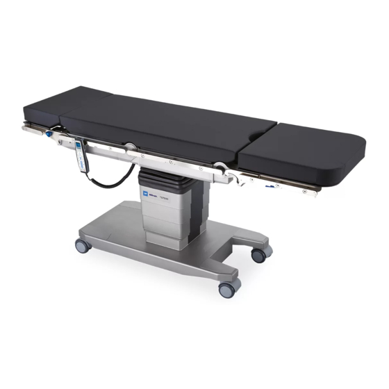
Page 17: Operating Table Overview
[2] Remote control [3] Seat section [4] Back section [5] Motorized leg section joint with fixture L [6] Side rail for seat section [7] Motorized back section joint Service Manual TruSystem 7000 Operating Table – 1 764 986 – 10/2016... - Page 18 [20] Equipotential bonding cable [21] Side rail for leg section joint [22] Head end [23] Foot end [24] Left side [25] Right side not available on all operating table variants Service Manual TruSystem 7000 Operating Table – 1 764 986 – 10/2016...
-
Page 19: Remote Control ▸System◂ (Secured) Menu
– 21. ▸Touch sensors inactive◂ – 22. ▸Test touch sensors◂ – 23. ▸Request service mode◂ NOTE Standby mode is switched off for most of the settings in the ▸Settings◂ menu. Service Manual TruSystem 7000 Operating Table – 1 764 986 – 10/2016... - Page 20 ▸LED test FB◂ During the remote control LED test, the background illumination of the individual keys is tested in sequence. ▸Start Flash update◂ No function at this time. Service Manual TruSystem 7000 Operating Table – 1 764 986 – 10/2016...
- Page 21 Upon activating the ▸Show all messages◂ function, all system information is displayed. The ▸Show all messages◂ is Service Manual TruSystem 7000 Operating Table – 1 764 986 – 10/2016...
- Page 22 Touch screen fields are shown on the display. When one of the individual fields is touched, the respective active field is marked yellow. 23. ▸Request service mode◂ Activate service mode Service Manual TruSystem 7000 Operating Table – 1 764 986 – 10/2016...
-
Page 23: Test Procedures
(see page 284). Conduct a complete functional test after service work is completed. Service Manual TruSystem 7000 Operating Table – 1 764 986 – 10/2016... -
Page 24: Safety Information For The Batteries (#1533137)
There are no special measures, such as a connection sequence on the power supply. A Service Manual TruSystem 7000 Operating Table – 1 764 986 – 10/2016... - Page 25 Trumpf Medical Technical Service. Important: the returns must be declared as hazardous materials of class 9/UN3480! Trumpf Medical will take responsibility for the environmentally proper disposal of the battery. Service Manual TruSystem 7000 Operating Table – 1 764 986 – 10/2016...
-
Page 26: Tools, Measuring Equipment And Auxiliary Tools
1798264 to check the toothed belt tension on the Trendelenburg and longitudinal travel motor Spring balance to check the toothed belt tension on the Trendelenburg and tilt motor Service Manual TruSystem 7000 Operating Table – 1 764 986 – 10/2016... - Page 27 4150054 Loctite 5699 sealant 4150065 omniFIT 100 M screw locking agent 4150018 omniFIT 200 M screw locking agent 4150020 Thread-locking adhesive UHU weak fast 4150046 Thermal grease 4150060 Service Manual TruSystem 7000 Operating Table – 1 764 986 – 10/2016...
- Page 28 4150050 Klüberlectric KR 44-120 1557674 Castrol Hyspin DSP 32 1864008 Mineral oil (viscosity of 32) for refilling the assembly Care and cleaning kit 4159014 Alcohol (degreasing agent) Service Manual TruSystem 7000 Operating Table – 1 764 986 – 10/2016...
-
Page 29: Preparing The Operating Table
Remove the pad from the table top so that it is not damaged during repair. During repair work, do not make any adjustments to the operating table except those explicitly specified. Service Manual TruSystem 7000 Operating Table – 1 764 986 – 10/2016... -
Page 30: Open And Close The Lower Column Cover
Install the lowest column cover on the pot (2 screws). Put on the pad. Switch on the operating table at the column keypad. Connect the operating table to the external power supply. TEST Perform a function test. Service Manual TruSystem 7000 Operating Table – 1 764 986 – 10/2016... -
Page 31: Open And Close The Top Column Cover
Insert the right top metal panel and attach to the frame (3 screws). Attach the top two metal panels to one another ( 2 screws). Slide the bellows down into the frame. Service Manual TruSystem 7000 Operating Table – 1 764 986 – 10/2016... - Page 32 Put on the pad. Switch on the operating table at the column keypad. Connect the operating table to the external power supply. TEST Perform a function test. Service Manual TruSystem 7000 Operating Table – 1 764 986 – 10/2016...
-
Page 33: Disconnecting And Reconnecting The Internal Power Supply On The Operating Table
Close the column cover (see chapter 8 on page 30). Put on the pad. Switch on the operating table at the column keypad. Connect the operating table to the external power supply. TEST Perform a function test. Service Manual TruSystem 7000 Operating Table – 1 764 986 – 10/2016... -
Page 34: Emergency Adjustment For The Lift
After placing the table on its side, do not activate the hydraulics system to prevent air from seeping into the hydraulic hoses. Side with the column keypad Service Manual TruSystem 7000 Operating Table – 1 764 986 – 10/2016... - Page 35 Clear the floor in front of the operating table and clean it if necessary. Right the operating table with the help of a second person. 20. Remove the multifunction tool. Service Manual TruSystem 7000 Operating Table – 1 764 986 – 10/2016...
- Page 36 Emergency adjustment for the lift 21. Remove the toothed wheel. TEST Perform a function test. Service Manual TruSystem 7000 Operating Table – 1 764 986 – 10/2016...
-
Page 37: Mechanical Parts Of The Table Top
For all screws ≥ M4 without split lock washers, use a medium- strength screw locking agent. After replacing a gear, always reset the level position of the motor and update the software. Service Manual TruSystem 7000 Operating Table – 1 764 986 – 10/2016... - Page 38 (10 screws, note the different lengths). When placing the table top, orient it to the openings not available on all operating table versions Service Manual TruSystem 7000 Operating Table – 1 764 986 – 10/2016...
- Page 39 10. Establish the internal power supply, close the column cover and turn on the operating table (see chapter 10 on page 33). 11. Put on the pad. TEST Perform a function test. Service Manual TruSystem 7000 Operating Table – 1 764 986 – 10/2016...
-
Page 40: Pad Plate
Place the pad plate back in its original mounting position. Place the pad plate onto the bars and install (6 screws). Put on the pad. TEST Perform a function test. Service Manual TruSystem 7000 Operating Table – 1 764 986 – 10/2016... -
Page 41: Center Box Cover
Establish the internal power supply, close the column cover and turn on the operating table (see chapter 10 on page 33). Put on the pad. TEST Perform a function test. Service Manual TruSystem 7000 Operating Table – 1 764 986 – 10/2016... -
Page 42: Leg Section Gear Box
(3 screws each). Make sure the sensor cable does not get pinched. Tap the 3 pins on each of the coupling plates into the gear box. Service Manual TruSystem 7000 Operating Table – 1 764 986 – 10/2016... - Page 43 17. Calibrate the leg section motor (CAN test center). See chapter 24.3 on page 266. 18. Update the software (see the software description from the CAN test center). TEST Perform function test and final check. Service Manual TruSystem 7000 Operating Table – 1 764 986 – 10/2016...
-
Page 44: Operating Table With Side Rail At The Joint
[1] (each with 3 screws inside and 1 screw outside). Pull out the sensor cable completely. Assembly Remove any adhesive residue from both coupling plates and degrease. Service Manual TruSystem 7000 Operating Table – 1 764 986 – 10/2016... - Page 45 16. Attach the leg section drive unit to the seat section bar (see chapter 13.4 on page 61). 17. Attach the pad plate to the seat section bars (see chapter 12.2 on page 40). Service Manual TruSystem 7000 Operating Table – 1 764 986 – 10/2016...
- Page 46 20. Calibrate the leg section motor (CAN test center). See chapter 24.3 on page 266. 21. Update the software (see the software description from the CAN test center). TEST Perform function test and final check. Service Manual TruSystem 7000 Operating Table – 1 764 986 – 10/2016...
-
Page 47: Back Section Gear Box
Glue a new self-adhesive, cover foil to the joint on the inside of the back section bar. Mount the standard rail to the back section bar (2 screws). Make sure to re-install the motor in its original position. Service Manual TruSystem 7000 Operating Table – 1 764 986 – 10/2016... - Page 48 12.2 on page 40). 16. Put on the pad. 17. Update the software (see the software description from the CAN test center). TEST Perform function test and final check. Service Manual TruSystem 7000 Operating Table – 1 764 986 – 10/2016...
-
Page 49: Energy Chain
(2 screws each). Attach ground wire_24 to the center box and the inside of the bar (each with 1 screw with 2 washers). Lay cable W166/W167 in the center box. Service Manual TruSystem 7000 Operating Table – 1 764 986 – 10/2016... - Page 50 13. Establish the internal power supply, close the column cover and turn on the operating table (see chapter 10 on page 33). 14. Put on the pad. TEST Perform function test and final check. Service Manual TruSystem 7000 Operating Table – 1 764 986 – 10/2016...
-
Page 51: Linear Guide
The operating table is completely replaced. Replacement operating tables are available through Trumpf Medical Technical Service. Securely package the operating table and send it back to Technical Service. Service Manual TruSystem 7000 Operating Table – 1 764 986 – 10/2016... -
Page 52: Longitudinal Travel Toothed Belt
The value on the belt tension meter must be 140 Hz (±5 Hz). Calibrate the longitudinal travel motor (CAN test center) See chapter 24.5 on page 267. Service Manual TruSystem 7000 Operating Table – 1 764 986 – 10/2016... - Page 53 (see chapter 10 on page 33). Put on the pad. TEST Perform recheck according to IEC 60601-1; perform function test and final check. Service Manual TruSystem 7000 Operating Table – 1 764 986 – 10/2016...
-
Page 54: Retrofit Kit For The Side Rail Of The Leg Section Joint
12. Secure the long side rail [14] from the retrofit kit to the gear box adapter [2]. 13. Repeat the steps 1. to 12. for the other side of the operating table. TEST Perform a function test. Service Manual TruSystem 7000 Operating Table – 1 764 986 – 10/2016... -
Page 55: Electrical Parts Of The Table Top
For all screws ≥ M4 without split lock washers, use a medium- strength screw locking agent. After replacing motors, always reset the level position and update the software. Service Manual TruSystem 7000 Operating Table – 1 764 986 – 10/2016... -
Page 56: Motor Controller Circuit Board
Attach the cover to the center box (see chapter 12.3 on page 41). Attach the pad plate to the seat section bars (see chapter 12.2 on page 40). not available on all operating table versions Service Manual TruSystem 7000 Operating Table – 1 764 986 – 10/2016... - Page 57 CAN test center. 11. Update the software (see the software description from the CAN test center). TEST Perform recheck according to IEC 60601-1; perform function test and final check. Service Manual TruSystem 7000 Operating Table – 1 764 986 – 10/2016...
-
Page 58: Communications Controller Circuit Board
Put on the pad. Calibrate the tilt sensor (see the software description from the CAN test center). Update the software (see the software description from the CAN test center). Service Manual TruSystem 7000 Operating Table – 1 764 986 – 10/2016... - Page 59 Communications controller circuit board 10. Adjust the system time via the WEB interface (service interface). TEST Perform recheck according to IEC 60601-1; perform function test and final check. Service Manual TruSystem 7000 Operating Table – 1 764 986 – 10/2016...
-
Page 60: Battery On The Communications Controller Circuit Board
(see chapter 10 on page 33). Put on the pad. Adjust the system time via the WEB interface (service interface). TEST Perform recheck according to IEC 60601-1; perform function test and final check. Service Manual TruSystem 7000 Operating Table – 1 764 986 – 10/2016... -
Page 61: Drive Unit For Leg Section
(2 screws each from above and below). Attach the end of the sensor cable to the pull wire and carefully pull the sensor cable into the bar. Service Manual TruSystem 7000 Operating Table – 1 764 986 – 10/2016... - Page 62 24.3 on page 266. 15. Update the software (see the software description from the CAN test center). TEST Perform recheck according to IEC 60601-1; perform function test and final check. Service Manual TruSystem 7000 Operating Table – 1 764 986 – 10/2016...
-
Page 63: Leg Section Motor
(see chapter 10 on page 33). Put on the pad. Calibrate the leg section motor (CAN test center). See chapter 24.3 on page 266. Service Manual TruSystem 7000 Operating Table – 1 764 986 – 10/2016... - Page 64 Leg section motor Update the software (see the software description from the CAN test center). TEST Perform recheck according to IEC 60601-1; perform function test and final check. Service Manual TruSystem 7000 Operating Table – 1 764 986 – 10/2016...
-
Page 65: Back Section Drive Unit (Back Section Bar)
Restore the original cable routing. Through the opening in the bar, connect both plugs of cable W169 and the sensor cable plug to the back section motor. Restore the original cable routing. Service Manual TruSystem 7000 Operating Table – 1 764 986 – 10/2016... - Page 66 13. Put on the pad. 14. Update the software (see the software description from the CAN test center). TEST Perform recheck according to IEC 60601-1; perform function test and final check. Service Manual TruSystem 7000 Operating Table – 1 764 986 – 10/2016...
-
Page 67: Back Section Motor
Attach the pad plate to the seat section bars (see chapter 12.2 on page 40). Attach the pad plate to the back section bars (see chapter 12.2 on page 40). Service Manual TruSystem 7000 Operating Table – 1 764 986 – 10/2016... - Page 68 10. Put on the pad. 11. Update the software (see the software description from the CAN test center). TEST Perform recheck according to IEC 60601-1; perform function test and final check. Service Manual TruSystem 7000 Operating Table – 1 764 986 – 10/2016...
-
Page 69: Longitudinal Travel Motor
(not tooth on tooth). Insert the longitudinal travel motor into the center box. Precisely place the toothed belt around the toothed belt pulley on the gear box and motor. Service Manual TruSystem 7000 Operating Table – 1 764 986 – 10/2016... - Page 70 11. Put on the pad. 12. Update the software (see the software description from the CAN test center). TEST Perform recheck according to IEC 60601-1; perform function test and final check. Service Manual TruSystem 7000 Operating Table – 1 764 986 – 10/2016...
-
Page 71: Can Distributor Circuit Board (Center Box)
Put on the pad. Update the software (see the software description from the CAN test center). TEST Perform recheck according to IEC 60601-1; perform function test and final check. Service Manual TruSystem 7000 Operating Table – 1 764 986 – 10/2016... -
Page 72: Can Distributor Circuit Board (Bar)
40). Establish the internal power supply, close the column cover and turn on the operating table (see chapter 10 on page 33). Put on the pad. Service Manual TruSystem 7000 Operating Table – 1 764 986 – 10/2016... - Page 73 CAN distributor circuit board (bar) Update the software (see the software description from the CAN test center). TEST Perform recheck according to IEC 60601-1; perform function test and final check. Service Manual TruSystem 7000 Operating Table – 1 764 986 – 10/2016...
-
Page 74: Endolight Interface Circuit Board
Put on the pad. Update the software (see the software description from the CAN test center). TEST Perform recheck according to IEC 60601-1; perform function test and final check. Service Manual TruSystem 7000 Operating Table – 1 764 986 – 10/2016... -
Page 75: Mechanical Parts Of The Column
Remove the metal panel with the column keypad (see chapter 14.2 on page 77). Assembly Attach the metal panel with the column keypad to the frame (see chapter 14.2 on page 77). Service Manual TruSystem 7000 Operating Table – 1 764 986 – 10/2016... - Page 76 Establish the internal power supply, close the column cover and turn on the operating table (see chapter 10 on page 33). Put on the pad. TEST Perform a function test. Service Manual TruSystem 7000 Operating Table – 1 764 986 – 10/2016...
-
Page 77: Metal Panel With The Column Keypad
Insert the deflector plate of the column controller into the suspension plate and mount it (2 screws). Slide the column cover up and close it (see chapter 9 on page 31). Service Manual TruSystem 7000 Operating Table – 1 764 986 – 10/2016... -
Page 78: Bellows
Attach the table top (see chapter 12.1 on page 38). Attach the cover to the center box (see chapter 12.3 on page 41). Service Manual TruSystem 7000 Operating Table – 1 764 986 – 10/2016... -
Page 79: Frame (Connection Ring)
Note the original installation position of the frame parts. Remove the complete frame (connection ring with connection plate bracket and slider plate) from the drive assembly [4] (2 screws each with washers). Service Manual TruSystem 7000 Operating Table – 1 764 986 – 10/2016... - Page 80 Establish the internal power supply, close the column cover and turn on the operating table (see chapter 10 on page 33). Put on the pad. TEST Perform a function test. Service Manual TruSystem 7000 Operating Table – 1 764 986 – 10/2016...
-
Page 81: Toothed Belt From The Trendelenburg Drive
Attach the toothed belt pulley (1 screw with washer). Service Manual TruSystem 7000 Operating Table – 1 764 986 – 10/2016... - Page 82 Take the bracket from the drive. f) Tighten the 4 screws [4] on the motor mounting bracket [5]. g) Remove the clamping screw [9] from the motor mounting bracket [5]. Service Manual TruSystem 7000 Operating Table – 1 764 986 – 10/2016...
- Page 83 (see chapter 10 on page 33). 13. Put on the pad. 14. Update the software (see the software description from the CAN test center). TEST Perform function test and final check. Service Manual TruSystem 7000 Operating Table – 1 764 986 – 10/2016...
-
Page 84: Toothed Belt From The Tilt Right Drive
Insert the loose toothed belt pulley precisely into the toothed belt and set in on the axis of the motor. Attach the toothed belt pulley (1 screw with washer). Service Manual TruSystem 7000 Operating Table – 1 764 986 – 10/2016... - Page 85 Take the bracket from the drive. f) Tighten the 4 screws [4] on the motor mounting bracket [5]. g) Remove the clamping screw [9] from the motor mounting bracket [5]. Service Manual TruSystem 7000 Operating Table – 1 764 986 – 10/2016...
- Page 86 (see chapter 10 on page 33). 12. Put on the pad. 13. Update the software (see the software description from the CAN test center). TEST Perform function test and final check. Service Manual TruSystem 7000 Operating Table – 1 764 986 – 10/2016...
-
Page 87: Toothed Belt From The Tilt Left Drive
Tighten the toothed belt: a) Lay the drive flat on a level surface. b) Screw in an M5 clamping screw [9] on the side of the motor mounting bracket [5]. Service Manual TruSystem 7000 Operating Table – 1 764 986 – 10/2016... - Page 88 Install the tilt left assembly (see chapter 15.9 on page 125). Attach the bellows (see chapter 14.3 on page 78). Attach the table top (see chapter 12.1 on page 38). Service Manual TruSystem 7000 Operating Table – 1 764 986 – 10/2016...
- Page 89 (see chapter 10 on page 33). 11. Put on the pad. 12. Update the software (see the software description from the CAN test center). TEST Perform function test and final check. Service Manual TruSystem 7000 Operating Table – 1 764 986 – 10/2016...
-
Page 90: Main Cardan
Establish the internal power supply, close the column cover and turn on the operating table (see chapter 10 on page 33). Put on the pad. TEST Perform function test and final check. Service Manual TruSystem 7000 Operating Table – 1 764 986 – 10/2016... -
Page 91: Ratchet Brace
CAN test center (PC) to move the main lift of the operating table so that the screws on the ratchet brace behind the Trendelenburg drive are accessible. Service Manual TruSystem 7000 Operating Table – 1 764 986 – 10/2016... - Page 92 10. Establish the internal power supply, close the column cover and turn on the operating table (see chapter 10 on page 33). 11. Put on the pad. TEST Perform a function test. Service Manual TruSystem 7000 Operating Table – 1 764 986 – 10/2016...
-
Page 93: Telescopic Spindle
With the help of another person, lay the operating table over onto the multifunction tool (side with the column keypad points down) and set it down securely on a flat, soft surface. Side with the column keypad Service Manual TruSystem 7000 Operating Table – 1 764 986 – 10/2016... - Page 94 Remove the old model plate from the guide column. Remove the adhesive label from the packaging of the new telescopic spindle and adhere it to the guide column. Service Manual TruSystem 7000 Operating Table – 1 764 986 – 10/2016...
- Page 95 Clear the floor in front of the operating table and clean it if necessary. Right the operating table with the help of a second person. Service Manual TruSystem 7000 Operating Table – 1 764 986 – 10/2016...
-
Page 96: Telescopic Spindle - Variant 2
(e.g., lift, tilt) are carried out on the operating table. Remove the table top (see chapter 12.1 on page 38). Loosen the bellows from the mounting plate (adhesive) and guide downward. Service Manual TruSystem 7000 Operating Table – 1 764 986 – 10/2016... - Page 97 Release the brake on the operating table (unlock the operating table). 13. Switch off the operating table and disconnect the internal power supply (see chapter 10 on page 33). Side with the column keypad Service Manual TruSystem 7000 Operating Table – 1 764 986 – 10/2016...
- Page 98 19. Remove the 4 screws [14] in the operating table base from the bearing shell [15]. 20. Carefully pull the spindle out of the column shaft. Service Manual TruSystem 7000 Operating Table – 1 764 986 – 10/2016...
- Page 99 22. Remove the spindle tube from the column shaft. Assembly Assembly is the same as for version 1 (see chapter 14.10.1 on page 93). Service Manual TruSystem 7000 Operating Table – 1 764 986 – 10/2016...
-
Page 100: Toothed Belt From The Main Drive
Remove the subfloor cover [3] on the table base (4 screws). Remove the telescopic spindle (see chapter 14.10 on page 93). Side with the column keypad Service Manual TruSystem 7000 Operating Table – 1 764 986 – 10/2016... - Page 101 Install the lift motor (but do not tighten the screws yet). Tighten the toothed belt: a) Check the toothed belt tension with a belt tension meter. The value must be 140 Hz (±5 Hz). If necessary, adjust the Service Manual TruSystem 7000 Operating Table – 1 764 986 – 10/2016...
- Page 102 15. Calibrate the lift motor (CAN test center). See chapter 24.7 on page 268. 16. Update the software (see the software description from the CAN test center). TEST Perform function test and final check. Service Manual TruSystem 7000 Operating Table – 1 764 986 – 10/2016...
-
Page 103: Toothed Washer Of The Telescopic Spindle
Remove the subfloor cover [3] on the table base (4 screws). Remove the telescopic spindle (see chapter 14.10 on page 93). Side with the column keypad Service Manual TruSystem 7000 Operating Table – 1 764 986 – 10/2016... - Page 104 Adjusting the spindle (see chapter 24.1 on page 262). Install the spindle (see chapter 14.10 on page 93). Service Manual TruSystem 7000 Operating Table – 1 764 986 – 10/2016...
- Page 105 17. Calibrate the lift motor (CAN test center). See chapter 24.7 on page 268. 18. Update the software (see the software description from the CAN test center). TEST Perform function test and final check. Service Manual TruSystem 7000 Operating Table – 1 764 986 – 10/2016...
-
Page 106: Electrical Parts Of The Column
(see chapter 10 on page 33). only for battery 1 [1] (next to the power supply unit [2]): Remove the battery bracket [3] from the power supply unit (1 screw with washer). Service Manual TruSystem 7000 Operating Table – 1 764 986 – 10/2016... - Page 107 Attach the cover over the coupling point on the table base (2 screws). Establish the internal power supply, close the column cover and turn on the operating table (see chapter 10 on page 33). Service Manual TruSystem 7000 Operating Table – 1 764 986 – 10/2016...
- Page 108 Put on the pad. Update the software (see the software description from the CAN test center). TEST Perform recheck according to IEC 60601-1; perform function test and final check. Service Manual TruSystem 7000 Operating Table – 1 764 986 – 10/2016...
-
Page 109: Power Supply Unit
Insert the ribbon cable of the connector board (ST2, power supply socket) in the socket on the side of the power supply unit (see circuit diagram on page 295). Service Manual TruSystem 7000 Operating Table – 1 764 986 – 10/2016... - Page 110 Put on the pad. Update the software (see the software description from the CAN test center). TEST Perform recheck according to IEC 60601-1; perform function test and final check. Service Manual TruSystem 7000 Operating Table – 1 764 986 – 10/2016...
-
Page 111: Power Supply Socket
(1 screw with washer and lock washer). Attach the connector board (ST2) load resistor to the column base (1 screw). Install the power supply unit (see chapter 15.2 on page 109). Service Manual TruSystem 7000 Operating Table – 1 764 986 – 10/2016... - Page 112 Put on the pad. Update the software (see the software description from the CAN test center). TEST Perform recheck according to IEC 60601-1; perform function test and final check. Service Manual TruSystem 7000 Operating Table – 1 764 986 – 10/2016...
-
Page 113: Column Keypad
(see chapter 10 on page 33). Put on the pad. Update the software (see the software description from the CAN test center). TEST Perform a function test. Service Manual TruSystem 7000 Operating Table – 1 764 986 – 10/2016... -
Page 114: Speaker
Insert the deflector plate of the column controller into the suspension plate and mount it (2 screws). Slide the column cover up and close it (see chapter 9 on page 31). Service Manual TruSystem 7000 Operating Table – 1 764 986 – 10/2016... -
Page 115: Lift Motor Assembly
Release the brake on the operating table (unlock the operating table). Switch off the operating table and disconnect the internal power supply (see chapter 10 on page 33). Side with the column keypad Service Manual TruSystem 7000 Operating Table – 1 764 986 – 10/2016... - Page 116 [6]. Remove the cable ties 11. Loosen the toothed belt tension: The hexagonal screw [3] on the tensioning device [4] should be almost fully tightened into the tensioning device. Service Manual TruSystem 7000 Operating Table – 1 764 986 – 10/2016...
- Page 117 Attach the protective cover to the lift motor (2 screws). Safety note: The operating table is extremely heavy; take extra care not to strain your back while righting it. A second person Service Manual TruSystem 7000 Operating Table – 1 764 986 – 10/2016...
-
Page 118: Trendelenburg Assembly
Disassembly Prepare the operating table (see chapter 7 on page 29). Switch off the operating table and disconnect the internal power supply (see chapter 10 on page 33). Service Manual TruSystem 7000 Operating Table – 1 764 986 – 10/2016... - Page 119 Unscrew the holder with plug contact (W164) [4] from the Trendelenburg assembly [3] (3 screws with washers). 13. Be sure to note the cable routing. Remove the cable attachment for the sensor cable under the mounting plate. Service Manual TruSystem 7000 Operating Table – 1 764 986 – 10/2016...
- Page 120 10. Attach the frame (connection ring) (see chapter 14.4 on page 79). 11. Attach the bellows (see chapter 14.3 on page 78). Service Manual TruSystem 7000 Operating Table – 1 764 986 – 10/2016...
- Page 121 24.6 on page 267. 21. Update the software (see the software description from the CAN test center). TEST Perform recheck according to IEC 60601-1; perform function test and final check. Service Manual TruSystem 7000 Operating Table – 1 764 986 – 10/2016...
-
Page 122: Tilt Right Assembly
11. Be sure to note the cable routing. Unfasten the cables from the tilt right assembly. 12. Unscrew the column controller [6] from the tilt right assembly [4] (1 screw with washer). Service Manual TruSystem 7000 Operating Table – 1 764 986 – 10/2016... - Page 123 10. Attach frame piece 1 to the tilt right assembly (2 screws with washers). 11. Attach the bellows (see chapter 14.3 on page 78). 12. Attach the table top (see chapter 12.1 on page 38). Service Manual TruSystem 7000 Operating Table – 1 764 986 – 10/2016...
- Page 124 267. 21. Update the software (see the software description from the CAN test center). TEST Perform recheck according to IEC 60601-1; perform function test and final check. Service Manual TruSystem 7000 Operating Table – 1 764 986 – 10/2016...
-
Page 125: Tilt Left Assembly
2 screws [7]) and place them securely on the column. 12. Remove the spiral cable holder [9] of cables W164 and W104 from the tilt left assembly [5] (2 screws each [10]). Service Manual TruSystem 7000 Operating Table – 1 764 986 – 10/2016... - Page 126 Check the cable routing and attachment and make sure that the cable cannot get between moving parts. 10. Attach frame piece 2 to frame piece 1 (2 screws from below). Service Manual TruSystem 7000 Operating Table – 1 764 986 – 10/2016...
- Page 127 267. 21. Update the software (see the software description from the CAN test center). TEST Perform recheck according to IEC 60601-1; perform function test and final check. Service Manual TruSystem 7000 Operating Table – 1 764 986 – 10/2016...
-
Page 128: Trendelenburg Motor
Risk of material damage to cardan bearings! Material wear due to improper assembly! During installation, make sure the assemblies are parallel! Mount floor plate to the suspension (4 screws from below). Service Manual TruSystem 7000 Operating Table – 1 764 986 – 10/2016... - Page 129 24.6 on page 267. 17. Update the software (see the software description from the CAN test center). TEST Perform recheck according to IEC 60601-1; perform function test and final check. Service Manual TruSystem 7000 Operating Table – 1 764 986 – 10/2016...
-
Page 130: Tilt Right Motor
(4 screws). Mount the toothed belt pulley and toothed belt on the tilt drive and tighten the toothed belt (see chapter 14.6 on page 84). Service Manual TruSystem 7000 Operating Table – 1 764 986 – 10/2016... - Page 131 267. 15. Update the software (see the software description from the CAN test center). TEST Perform recheck according to IEC 60601-1; perform function test and final check. Service Manual TruSystem 7000 Operating Table – 1 764 986 – 10/2016...
-
Page 132: Tilt Left Motor
(4 screws). Mount the toothed belt pulley and toothed belt on the tilt drive and tighten the toothed belt (see chapter 14.7 on page 87). Service Manual TruSystem 7000 Operating Table – 1 764 986 – 10/2016... - Page 133 267. 14. Update the software (see the software description from the CAN test center). TEST Perform recheck according to IEC 60601-1; perform function test and final check. Service Manual TruSystem 7000 Operating Table – 1 764 986 – 10/2016...
-
Page 134: Connector / Power Supply / Relay Board (Power Supply Socket)
The boards are contained in the power supply socket that requires a serial number. If one of the boards is defective, the power supply socket is replaced (see chapter 15.3 on page 111). Service Manual TruSystem 7000 Operating Table – 1 764 986 – 10/2016... -
Page 135: Column Controller Circuit Board
Do not interchange the connections! Maintain the plug and socket assignments (see circuit diagram on page 295). Restore the original cable routing. Insert all the plugs into the sockets on the circuit board. Service Manual TruSystem 7000 Operating Table – 1 764 986 – 10/2016... - Page 136 10. Put on the pad. 11. Update the software (see the software description from the CAN test center). TEST Perform recheck according to IEC 60601-1; perform function test and final check. Service Manual TruSystem 7000 Operating Table – 1 764 986 – 10/2016...
-
Page 137: Cardan With Sensor (Trendelenburg Drive)
The motor calibration is lost and must be repeated if the spindle is twisted. Carefully knock (nylon hammer) the outer bearing [4] from the cardan [5] and the bearing plate [6]. Service Manual TruSystem 7000 Operating Table – 1 764 986 – 10/2016... - Page 138 11. Establish the internal power supply, close the column cover and turn on the operating table (see chapter 10 on page 33). 12. Put on the pad. TEST Perform function test and final check. Service Manual TruSystem 7000 Operating Table – 1 764 986 – 10/2016...
-
Page 139: Ism Module Circuit Board
Remove the ISM module from the holder [3] (1 plastic screw). Assembly Note the original mounting position of the ISM module. Install the ISM module on the holder (1 plastic screw). Service Manual TruSystem 7000 Operating Table – 1 764 986 – 10/2016... - Page 140 Fix new sticker in the same position. Update the software (see the software description from the CAN test center). TEST Perform recheck according to IEC 60601-1; perform function test and final check. Service Manual TruSystem 7000 Operating Table – 1 764 986 – 10/2016...
-
Page 141: Retrofit Ism Module (Mat. No. 2064680)
Fit the holder [8] with the ISM module [7] to the top of the suspension plate [9] (1 screw with disc). 10. Insert the new cable adapter plug into the ISM module socket. Service Manual TruSystem 7000 Operating Table – 1 764 986 – 10/2016... - Page 142 Perform recheck according to IEC 60601-1; perform function test and final check. 20. Completely fill in the form (doc. no. 4900568) from the retrofit set, and fax or mail to Trumpf Medical technical customer service. Service Manual TruSystem 7000 Operating Table – 1 764 986 – 10/2016...
-
Page 143: Mechanical Parts Of The Table Base
The operating table may not be released to the customer if parts fell in and were not removed. For all screws ≥ M4 without split lock washers, use a medium- strength screw locking agent. Service Manual TruSystem 7000 Operating Table – 1 764 986 – 10/2016... -
Page 144: Wheel
Right the operating table with the help of a second person. Remove the multifunction tool. Remove the toothed wheel. Service Manual TruSystem 7000 Operating Table – 1 764 986 – 10/2016... - Page 145 Wheel Switch on the operating table (see chapter 10 on page 33). Lock operating table (brake) Put on the pad. TEST Perform function test and final check. Service Manual TruSystem 7000 Operating Table – 1 764 986 – 10/2016...
-
Page 146: Hinged Foot On Wheel (Floor Lock)
(necessary for righting the table) Safety note: The operating table is extremely heavy; take extra care not to strain your back while righting it. A second person Service Manual TruSystem 7000 Operating Table – 1 764 986 – 10/2016... - Page 147 Remove the multifunction tool. Remove the toothed wheel. Lock operating table (brake) Put on the pad. TEST Perform function test and final check. Service Manual TruSystem 7000 Operating Table – 1 764 986 – 10/2016...
-
Page 148: Electrical Parts Of The Table Base
For this reason, do not activate the hydraulics on the operating table if the operating table has been placed on its side with the column keypad pointing down. Service Manual TruSystem 7000 Operating Table – 1 764 986 – 10/2016... -
Page 149: Drive Unit
Remove the subfloor cover [3] from the table base (4 screws). Remove the right cover [4] from the table base (4 screws). Side without the column keypad Service Manual TruSystem 7000 Operating Table – 1 764 986 – 10/2016... - Page 150 Tighten the clamp on the quick connector and connect the hydraulic hose to the assembly (quick connectors) (see For an operating table with an electric drive unit only. Service Manual TruSystem 7000 Operating Table – 1 764 986 – 10/2016...
- Page 151 13. Put on the pad. 14. Update the software (see the software description from the CAN test center). TEST Perform recheck according to IEC 60601-1; perform function test and final check. Service Manual TruSystem 7000 Operating Table – 1 764 986 – 10/2016...
-
Page 152: Control Module
Mount the control module in the table base (4 nuts). Insert all plugs into the sockets on the control module (see circuit diagram on page 295). Side with the column keypad Service Manual TruSystem 7000 Operating Table – 1 764 986 – 10/2016... - Page 153 (see chapter 10 on page 33). Lock operating table (brake) Put on the pad. TEST Perform recheck according to IEC 60601-1; perform function test and final check. Service Manual TruSystem 7000 Operating Table – 1 764 986 – 10/2016...
-
Page 154: Line Power Socket
(see chapter 10 on page 33). Put on the pad. TEST Perform recheck according to IEC 60601-1; perform function test and final check. Service Manual TruSystem 7000 Operating Table – 1 764 986 – 10/2016... -
Page 155: Power Input Fuses
Establish the internal power supply, close the column cover and turn on the operating table (see chapter 10 on page 33). Put on the pad. TEST Perform function test and final check. Service Manual TruSystem 7000 Operating Table – 1 764 986 – 10/2016... -
Page 156: Buttons
After placing the table on its side, do not activate the hydraulics system to prevent air from seeping into the hydraulic hoses. Remove the left cover [3] under the table base (4 screws). Side with the column keypad Service Manual TruSystem 7000 Operating Table – 1 764 986 – 10/2016... - Page 157 (see chapter 10 on page 33). 10. Lock operating table (brake) 11. Put on the pad. TEST Perform recheck according to IEC 60601-1; perform function test and final check. Service Manual TruSystem 7000 Operating Table – 1 764 986 – 10/2016...
-
Page 158: Hydraulic Parts Of The Table Base
The assembly valves may become leaky if dirt or metal particles are deposited in the valves. Always make sure the quick-connect couplings are clean and that, when Service Manual TruSystem 7000 Operating Table – 1 764 986 – 10/2016... - Page 159 Therefore, do not activate the hydraulics on the operating table if the operating table has been placed on its side with the column keypad pointing down. Service Manual TruSystem 7000 Operating Table – 1 764 986 – 10/2016...
-
Page 160: Refilling Oil In The Assembly
[2] and oil container [3]. Refill the oil until the oil level [4] is between the minimum [5] and maximum [6] marks. Install the plug screw [1] with 10 Nm. Service Manual TruSystem 7000 Operating Table – 1 764 986 – 10/2016... -
Page 161: Bleeding The Hydraulic System
10 times using the CAN test center. Release the first 3 or 4 times with the E MERGENCY RELEASE Side without the column keypad Service Manual TruSystem 7000 Operating Table – 1 764 986 – 10/2016... - Page 162 MERGENCY RELEASE 13. Remove the multifunction tool. 14. Remove the toothed wheel. 15. Lock operating table (brake) 16. Put on the pad. TEST Perform function test and final check. Service Manual TruSystem 7000 Operating Table – 1 764 986 – 10/2016...
-
Page 163: Coil On The Pump Assembly
Remove the center cover [3] under the table base (4 screws with washers) and store it carefully. Disconnect the plug from the coil. Side without the column keypad Service Manual TruSystem 7000 Operating Table – 1 764 986 – 10/2016... - Page 164 (for example due to triggering the button). 11. Establish the internal power supply, close the column cover and turn on the operating table (see chapter 10 on page 33). 12. Lock operating table (brake) Service Manual TruSystem 7000 Operating Table – 1 764 986 – 10/2016...
- Page 165 Coil on the pump assembly 13. Put on the pad. TEST Perform recheck according to IEC 60601-1; perform function test and final check. Service Manual TruSystem 7000 Operating Table – 1 764 986 – 10/2016...
-
Page 166: Locking Cylinder With Hose
Remove the snap ring [3] from the floor lock [4] and pull off the wheel [5]. Side without the column keypad Service Manual TruSystem 7000 Operating Table – 1 764 986 – 10/2016... - Page 167 35 mm. Finally, check the cable routing and fastening and make sure that the cable cannot independently slide or get between moving parts! Service Manual TruSystem 7000 Operating Table – 1 764 986 – 10/2016...
- Page 168 (see chapter 10 on page 33). 16. Lock operating table (brake) 17. Put on the pad. TEST Perform recheck according to IEC 60601-1; perform function test and final check. Service Manual TruSystem 7000 Operating Table – 1 764 986 – 10/2016...
-
Page 169: Hose #1 Through #4 With Coupling (On The Locking Cylinder)
Remove the snap ring [3] from the floor lock [4] and pull off the wheel [5]. Side without the column keypad Service Manual TruSystem 7000 Operating Table – 1 764 986 – 10/2016... - Page 170 If necessary, cover the locking cylinder opening with a lint-free cloth. Assembly The hose is delivered without oil. Check the installation depth of the brass ring (seal) in the Service Manual TruSystem 7000 Operating Table – 1 764 986 – 10/2016...
- Page 171 RELEASE system. Make sure the floor locks retract after the procedure (necessary to right the table). Then disconnect the internal power supply. Service Manual TruSystem 7000 Operating Table – 1 764 986 – 10/2016...
- Page 172 18. Replace the label over the E button. MERGENCY RELEASE 19. Establish the internal power supply, close the column cover and turn on the operating table (see chapter 10 on page 33). Service Manual TruSystem 7000 Operating Table – 1 764 986 – 10/2016...
- Page 173 Hose #1 through #4 with coupling (on the locking cylinder) 20. Lock operating table (brake) 21. Put on the pad. TEST Perform recheck according to IEC 60601-1; perform function test and final check. Service Manual TruSystem 7000 Operating Table – 1 764 986 – 10/2016...
-
Page 174: Assembly With Valve Block
Disconnect the plug of the cable for the hydraulic pump motor (M-HY) from the control module (see circuit diagram on page 295) and expose the cable. Side without the column keypad Service Manual TruSystem 7000 Operating Table – 1 764 986 – 10/2016... - Page 175 Insert the coil into its original position in the magnet housing. There has to be a gap of between 0.5 mm and 1 mm between the magnet housing and the assembly (use a thickness gauge). Service Manual TruSystem 7000 Operating Table – 1 764 986 – 10/2016...
- Page 176 (see chapter 10 on page 33). 17. Lock operating table (brake) 18. Put on the pad. TEST Perform recheck according to IEC 60601-1; perform function test and final check. Service Manual TruSystem 7000 Operating Table – 1 764 986 – 10/2016...
-
Page 177: Cabling Overview
198 controller circuit board 1726737 W191 Cable from the foot-end Endolight interface Chapter 20.11, circuit board to the motor controller circuit page 198 board Service Manual TruSystem 7000 Operating Table – 1 764 986 – 10/2016... - Page 178 (power board PB1) page 227 1497360 Trendelenburg Cable from the sensor on the Chapter 15.15, power sensor Trendelenburg drive (cardan joint) to motor page 137 controller circuit board Service Manual TruSystem 7000 Operating Table – 1 764 986 – 10/2016...
- Page 179 256 1717944 Ground wire _25 Ground wire from the line power socket to Chapter 22.12, the column base page 258 not available on all operating table versions. Service Manual TruSystem 7000 Operating Table – 1 764 986 – 10/2016...
- Page 180 For all screws ≥ M4 without split lock washers, use a medium- strength screw locking agent. Finally, check the cable routing and fastening and make sure that the cable cannot independently slide or get between moving parts! Service Manual TruSystem 7000 Operating Table – 1 764 986 – 10/2016...
-
Page 181: Ground Wire_24
Attach the cover to the center box (see chapter 12.3 on page 41). Attach the pad plate to the seat section bars (see chapter 12.2 on page 40). Service Manual TruSystem 7000 Operating Table – 1 764 986 – 10/2016... - Page 182 (see chapter 10 on page 33). 11. Put on the pad. TEST Perform recheck according to IEC 60601-1; perform function test and final check. Service Manual TruSystem 7000 Operating Table – 1 764 986 – 10/2016...
-
Page 183: Cable W174
(see chapter 10 on page 33). Put on the pad. TEST Perform recheck according to IEC 60601-1; perform function test and final check. Service Manual TruSystem 7000 Operating Table – 1 764 986 – 10/2016... -
Page 184: Cable W165
(see chapter 10 on page 33). Put on the pad. TEST Perform recheck according to IEC 60601-1; perform function test and final check. Service Manual TruSystem 7000 Operating Table – 1 764 986 – 10/2016... -
Page 185: Cable W166 And W167
Restore the original cable routing. Pull cable W166/W167 through the recess on the bar cap and close the cap (4 screws). Make sure that no cables are pinched. Service Manual TruSystem 7000 Operating Table – 1 764 986 – 10/2016... - Page 186 (see chapter 10 on page 33). 17. Put on the pad. TEST Perform recheck according to IEC 60601-1; perform function test and final check. Service Manual TruSystem 7000 Operating Table – 1 764 986 – 10/2016...
-
Page 187: Cable W168
(see chapter 10 on page 33). Put on the pad. TEST Perform recheck according to IEC 60601-1; perform function test and final check. Service Manual TruSystem 7000 Operating Table – 1 764 986 – 10/2016... -
Page 188: Cable W169
(see chapter 10 on page 33). Put on the pad. TEST Perform recheck according to IEC 60601-1; perform function test and final check. Service Manual TruSystem 7000 Operating Table – 1 764 986 – 10/2016... -
Page 189: Cable W170 And W171
Route cable W170/W171 in the center box. Ensure that cable W170 does not get pinched or damaged; the gap between the gear box and the center box is very narrow. Service Manual TruSystem 7000 Operating Table – 1 764 986 – 10/2016... - Page 190 (see chapter 10 on page 33). 11. Put on the pad. TEST Perform recheck according to IEC 60601-1; perform function test and final check. Service Manual TruSystem 7000 Operating Table – 1 764 986 – 10/2016...
-
Page 191: Coupling Point Sensor
Press the sliding disk against the gear box and mount the outer coupling plate to the gear box (3 screws). Make sure the sensor cable does not get pinched. Service Manual TruSystem 7000 Operating Table – 1 764 986 – 10/2016... -
Page 192: Operating Table With Side Rail At The Joint
41). Remove the drive unit of the leg section (see chapter 13.4 on page 61). Remove the cover plate [1] from the inner coupling plate [2] (1 screw). Service Manual TruSystem 7000 Operating Table – 1 764 986 – 10/2016... - Page 193 10. Pull the sensor cable through the cable pass-through. 11. Carefully pull the sensor cable taut and mount the cover plate with the cable pass-through onto the inner coupling plate (1 screw). Service Manual TruSystem 7000 Operating Table – 1 764 986 – 10/2016...
- Page 194 (see chapter 10 on page 33). 19. Put on the pad. TEST Perform recheck according to IEC 60601-1; perform function test and final check. Service Manual TruSystem 7000 Operating Table – 1 764 986 – 10/2016...
-
Page 195: Or Sensor
(see chapter 10 on page 33). Put on the pad. TEST Perform recheck according to IEC 60601-1; perform function test and final check. Service Manual TruSystem 7000 Operating Table – 1 764 986 – 10/2016... -
Page 196: Cable W193
Tighten the counter nut. Connect the shielded connection to the connection contact of the socket. Restore the original cable routing. Route cable W193 in the center box. Service Manual TruSystem 7000 Operating Table – 1 764 986 – 10/2016... - Page 197 (see chapter 10 on page 33). 10. Put on the pad. TEST Perform recheck according to IEC 60601-1; perform function test and final check. Service Manual TruSystem 7000 Operating Table – 1 764 986 – 10/2016...
-
Page 198: Cable W190/W191
(see chapter 10 on page 33). Put on the pad. TEST Perform recheck according to IEC 60601-1; perform function test and final check. Service Manual TruSystem 7000 Operating Table – 1 764 986 – 10/2016... -
Page 199: Column Cables
For all screws ≥ M4 without split lock washers, use a medium- strength screw locking agent. Finally, check the cable routing and fastening and make sure that the cable cannot get between moving parts! Service Manual TruSystem 7000 Operating Table – 1 764 986 – 10/2016... -
Page 200: Cable W104
[7] and loosen the two screws [8] on the column base. Guide the cable deflector out of the screws [8] on the column base and remove it. Service Manual TruSystem 7000 Operating Table – 1 764 986 – 10/2016... - Page 201 W104 from the suspension plate [17] (1 screw with 2 washers). 18. Remove cable W104. Assembly Attach the spiral cable holder of cable W104 to the tilt left Service Manual TruSystem 7000 Operating Table – 1 764 986 – 10/2016...
- Page 202 (see chapter 10 on page 33). 17. Put on the pad. TEST Perform recheck according to IEC 60601-1; perform function test and final check. Service Manual TruSystem 7000 Operating Table – 1 764 986 – 10/2016...
-
Page 203: Cable W159
2. Note the original mounting position of the cable hold-down clamp! Do not jam cables! Service Manual TruSystem 7000 Operating Table – 1 764 986 – 10/2016... - Page 204 (see chapter 10 on page 33). Put on the pad. TEST Perform recheck according to IEC 60601-1; perform function test and final check. Service Manual TruSystem 7000 Operating Table – 1 764 986 – 10/2016...
-
Page 205: Cable W160
Plug the plug at the other end of cable W160 into the socket of the coupling point (see circuit diagram on page 295). The opening is at the side of the table base between the lift motor and battery 2. Service Manual TruSystem 7000 Operating Table – 1 764 986 – 10/2016... - Page 206 (see chapter 10 on page 33). Put on the pad. TEST Perform recheck according to IEC 60601-1; perform function test and final check. Service Manual TruSystem 7000 Operating Table – 1 764 986 – 10/2016...
-
Page 207: Cable W161
(ST2) (power supply socket) (see circuit diagram on page 295). Plug the plug at the other end of cable W161 into the socket of the coupling point (see circuit diagram on page 295). The Service Manual TruSystem 7000 Operating Table – 1 764 986 – 10/2016... - Page 208 (see chapter 10 on page 33). Put on the pad. TEST Perform recheck according to IEC 60601-1; perform function test and final check. Service Manual TruSystem 7000 Operating Table – 1 764 986 – 10/2016...
-
Page 209: Cable W164
10. Note the cable routing and attachment. Unfasten cable W164 [4] under the mounting plate [5]. 11. Note the cable routing and attachment. Unfasten cable W164 [4] from the suspension plate [6]. Service Manual TruSystem 7000 Operating Table – 1 764 986 – 10/2016... - Page 210 [11] and place on non-conductive material of the column. 14. Be sure to note the cable routing. Unscrew the holder with plug contact (W164) [12] from the Trendelenburg assembly [11] (3 screws with washers). Service Manual TruSystem 7000 Operating Table – 1 764 986 – 10/2016...
- Page 211 Mount the cable deflector to the power supply unit (2 screws on the top) and tighten the two screws on the column base. Service Manual TruSystem 7000 Operating Table – 1 764 986 – 10/2016...
- Page 212 (see chapter 10 on page 33). 19. Put on the pad. TEST Perform recheck according to IEC 60601-1; perform function test and final check. Service Manual TruSystem 7000 Operating Table – 1 764 986 – 10/2016...
-
Page 213: Cable W134
Refasten cable W134 from the power supply unit up to battery Set the cable deflector onto the two screws on the column base and slide it flush against the power supply unit. Mount the Service Manual TruSystem 7000 Operating Table – 1 764 986 – 10/2016... - Page 214 (see chapter 10 on page 33). Put on the pad. TEST Perform recheck according to IEC 60601-1; perform function test and final check. Service Manual TruSystem 7000 Operating Table – 1 764 986 – 10/2016...
-
Page 215: Cable W172
2 [8] to the coupling point [9] on the table base. Remove cable W172 [6]. Assembly Restore the original cable routing. Route cable W172 in the column pot. Service Manual TruSystem 7000 Operating Table – 1 764 986 – 10/2016... - Page 216 (see chapter 10 on page 33). Put on the pad. TEST Perform recheck according to IEC 60601-1; perform function test and final check. Service Manual TruSystem 7000 Operating Table – 1 764 986 – 10/2016...
-
Page 217: Cable W173
Mount the pad plate to the bars (6 screws). Establish the internal power supply, close the column cover and turn on the operating table (see chapter 10 on page 33). Service Manual TruSystem 7000 Operating Table – 1 764 986 – 10/2016... - Page 218 Cable W173 10. Put on the pad. TEST Perform recheck according to IEC 60601-1; perform function test and final check. Service Manual TruSystem 7000 Operating Table – 1 764 986 – 10/2016...
-
Page 219: Cable W107
295). Connect the plug and shielded connection of cable W107 to the lift motor. Attach the protective cover to the lift motor (2 screws). Note the shield support. Service Manual TruSystem 7000 Operating Table – 1 764 986 – 10/2016... - Page 220 (see chapter 10 on page 33). Put on the pad. TEST Perform recheck according to IEC 60601-1; perform function test and final check. Service Manual TruSystem 7000 Operating Table – 1 764 986 – 10/2016...
-
Page 221: Cable W108
Insert the plug of cable W108 into the socket on the column controller (see circuit diagram on page 295). Connect plug and shielded connection of cable W108 to the tilt left motor. Service Manual TruSystem 7000 Operating Table – 1 764 986 – 10/2016... - Page 222 (see chapter 10 on page 33). 11. Put on the pad. TEST Perform recheck according to IEC 60601-1; perform function test and final check. Service Manual TruSystem 7000 Operating Table – 1 764 986 – 10/2016...
-
Page 223: Cable W109
Insert the plug of cable W109 into the socket on the column controller (see circuit diagram on page 295). Connect plug and shielded connection of cable W109 to the tilt right motor. Service Manual TruSystem 7000 Operating Table – 1 764 986 – 10/2016... - Page 224 (see chapter 10 on page 33). 11. Put on the pad. TEST Perform recheck according to IEC 60601-1; perform function test and final check. Service Manual TruSystem 7000 Operating Table – 1 764 986 – 10/2016...
-
Page 225: Cable W110
Insert the plug of cable W110 into the socket on the column controller (see circuit diagram on page 295). Connect plug and shielded connection of cable W110 to the Trendelenburg motor. Service Manual TruSystem 7000 Operating Table – 1 764 986 – 10/2016... - Page 226 (see chapter 10 on page 33). 11. Put on the pad. TEST Perform recheck according to IEC 60601-1; perform function test and final check. Service Manual TruSystem 7000 Operating Table – 1 764 986 – 10/2016...
-
Page 227: Reset Switch
Remove the reset switch [10] from the column pot [9] (2 screws). Assembly Mount the reset switch to the column pot (2 screws). The cable connection faces down. Service Manual TruSystem 7000 Operating Table – 1 764 986 – 10/2016... - Page 228 (see chapter 10 on page 33). Put on the pad. TEST Perform recheck according to IEC 60601-1; perform function test and final check. Service Manual TruSystem 7000 Operating Table – 1 764 986 – 10/2016...
-
Page 229: Power Sensor On The Trendelenburg Drive
The power sensor is permanently attached to the cardan and is not replaced separately. In the event of a defect, the cardan is replaced (see chapter 15.15 on page 137). Service Manual TruSystem 7000 Operating Table – 1 764 986 – 10/2016... -
Page 230: Cable Adapter
Unfasten the cable at the upper attachment point (cable holder on the base of the mounting plate). Remove the cable adapter plug from the underside of the motor controller circuit board. The motor controller circuit Service Manual TruSystem 7000 Operating Table – 1 764 986 – 10/2016... - Page 231 Put on the pad. Update the software (see the software description from the CAN test center). TEST Perform recheck according to IEC 60601-1; perform function test and final check. Service Manual TruSystem 7000 Operating Table – 1 764 986 – 10/2016...
- Page 232 For all screws ≥ M4 without split lock washers, use a medium- strength screw locking agent. Finally, check the cable routing and fastening and make sure that the cable cannot get between moving parts! Service Manual TruSystem 7000 Operating Table – 1 764 986 – 10/2016...
-
Page 233: Cable W150
Remove the center cover [4] under the table base (4 screws with washers) and store it carefully. Remove the cover [5] over the coupling point on the side of table base (2 screws). Side with the column keypad Service Manual TruSystem 7000 Operating Table – 1 764 986 – 10/2016... - Page 234 10. Remove the toothed wheel. 11. Establish the internal power supply, close the column cover and turn on the operating table (see chapter 10 on page 33). 12. Lock operating table (brake) Service Manual TruSystem 7000 Operating Table – 1 764 986 – 10/2016...
- Page 235 Cable W150 13. Put on the pad. TEST Perform recheck according to IEC 60601-1; perform function test and final check. Service Manual TruSystem 7000 Operating Table – 1 764 986 – 10/2016...
-
Page 236: Cable W151
Remove the cover [5] over the coupling point [7] on the side of table base (2 screws). Side with the column keypad Service Manual TruSystem 7000 Operating Table – 1 764 986 – 10/2016... - Page 237 (see chapter 10 on page 33). 11. Lock operating table (brake) 12. Put on the pad. TEST Perform recheck according to IEC 60601-1; perform function test and final check. Service Manual TruSystem 7000 Operating Table – 1 764 986 – 10/2016...
-
Page 238: Cable W152
Remove the center cover [4] under the table base (4 screws with washers) and store it carefully. Side with the column keypad Service Manual TruSystem 7000 Operating Table – 1 764 986 – 10/2016... - Page 239 (see chapter 10 on page 33). 12. Lock operating table (brake) 13. Put on the pad. TEST Perform recheck according to IEC 60601-1; perform function test and final check. Service Manual TruSystem 7000 Operating Table – 1 764 986 – 10/2016...
-
Page 240: Cable W153
After placing the table on its side, do not activate the hydraulics system to prevent air from seeping into the hydraulic hoses. Remove the left cover [3] under the table base (4 screws). Side with the column keypad Service Manual TruSystem 7000 Operating Table – 1 764 986 – 10/2016... - Page 241 (see chapter 10 on page 33). 10. Lock operating table (brake) 11. Put on the pad. TEST Perform recheck according to IEC 60601-1; perform function test and final check. Service Manual TruSystem 7000 Operating Table – 1 764 986 – 10/2016...
-
Page 242: Cable W154
After placing the table on its side, do not activate the hydraulics system to prevent air from seeping into the hydraulic hoses. Remove the left cover [3] under the table base (4 screws). Side with the column keypad Service Manual TruSystem 7000 Operating Table – 1 764 986 – 10/2016... - Page 243 (see chapter 10 on page 33). 10. Lock operating table (brake) 11. Put on the pad. TEST Perform recheck according to IEC 60601-1; perform function test and final check. Service Manual TruSystem 7000 Operating Table – 1 764 986 – 10/2016...
-
Page 244: Cable W155
Remove the cover [5] over the coupling point [7] on the side of table base (2 screws). Side with the column keypad Service Manual TruSystem 7000 Operating Table – 1 764 986 – 10/2016... - Page 245 10. Remove the toothed wheel. 11. Establish the internal power supply, close the column cover and turn on the operating table (see chapter 10 on page 33). 12. Lock operating table (brake) Service Manual TruSystem 7000 Operating Table – 1 764 986 – 10/2016...
- Page 246 Cable W155 13. Put on the pad. TEST Perform recheck according to IEC 60601-1; perform function test and final check. Service Manual TruSystem 7000 Operating Table – 1 764 986 – 10/2016...
-
Page 247: Cable W177
After placing the table on its side, do not activate the hydraulics system to prevent air from seeping into the hydraulic hoses. Remove the left cover [3] under the table base (4 screws). Side with the column keypad Service Manual TruSystem 7000 Operating Table – 1 764 986 – 10/2016... - Page 248 (see chapter 10 on page 33). 10. Lock operating table (brake) 11. Put on the pad. TEST Perform recheck according to IEC 60601-1; perform function test and final check. Service Manual TruSystem 7000 Operating Table – 1 764 986 – 10/2016...
-
Page 249: Cable W156 And W158
Remove the center cover [4] under the table base (4 screws with washers) and store it carefully. Side with the column keypad Service Manual TruSystem 7000 Operating Table – 1 764 986 – 10/2016... - Page 250 (see chapter 10 on page 33). 11. Lock operating table (brake) 12. Put on the pad. TEST Perform recheck according to IEC 60601-1; perform function test and final check. Service Manual TruSystem 7000 Operating Table – 1 764 986 – 10/2016...
-
Page 251: Cable W157
Remove the center cover [4] under the table base (4 screws with washers) and store it carefully. Side with the column keypad Service Manual TruSystem 7000 Operating Table – 1 764 986 – 10/2016... - Page 252 (see chapter 10 on page 33). 11. Lock operating table (brake) 12. Put on the pad. TEST Perform recheck according to IEC 60601-1; perform function test and final check. Service Manual TruSystem 7000 Operating Table – 1 764 986 – 10/2016...
-
Page 253: Cable W175
After placing the table on its side, do not activate the hydraulics system to prevent air from seeping into the hydraulic hoses. Remove the left cover [3] under the table base (4 screws). Side with the column keypad Service Manual TruSystem 7000 Operating Table – 1 764 986 – 10/2016... - Page 254 Safety note: The operating table is extremely heavy; take extra care not to strain your back while righting it. A second person is needed to right the operating table. Clear the floor in front Service Manual TruSystem 7000 Operating Table – 1 764 986 – 10/2016...
- Page 255 (see chapter 10 on page 33). 11. Lock operating table (brake) 12. Put on the pad. TEST Perform recheck according to IEC 60601-1; perform function test and final check. Service Manual TruSystem 7000 Operating Table – 1 764 986 – 10/2016...
-
Page 256: Cable W162
Remove the center cover [4] under the table base (4 screws with washers) and store it carefully. Side with the column keypad Service Manual TruSystem 7000 Operating Table – 1 764 986 – 10/2016... - Page 257 (see chapter 10 on page 33). Lock operating table (brake) Put on the pad. TEST Perform recheck according to IEC 60601-1; perform function test and final check. Service Manual TruSystem 7000 Operating Table – 1 764 986 – 10/2016...
-
Page 258: Ground Wire _25
After placing the table on its side, do not activate the hydraulics system to prevent air from seeping into the hydraulic hoses. Remove the left cover [3] under the table base (4 screws). Side with the column keypad Service Manual TruSystem 7000 Operating Table – 1 764 986 – 10/2016... - Page 259 (see chapter 10 on page 33). Lock operating table (brake) Put on the pad. TEST Perform recheck according to IEC 60601-1; perform function test and final check. Service Manual TruSystem 7000 Operating Table – 1 764 986 – 10/2016...
-
Page 260: Quick-Connect Coupling On The Assembly
1 or 2 turns. Cover the coupling with a lint-free cloth since oil drops can spurt out. Open the quick-connect coupling and remove it. Perform service work. Connect the quick-connect coupling. Service Manual TruSystem 7000 Operating Table – 1 764 986 – 10/2016... - Page 261 Quick-connect coupling on the assembly Screw the loosened coupling back on with a torque of 5 (+2) Bleed the hydraulic system Service Manual TruSystem 7000 Operating Table – 1 764 986 – 10/2016...
-
Page 262: Adjustment And Calibration Tasks
The spindle may be adjusted only when it is removed. Remove the 4 screws [2] at the top of the spindle tube [1]; remove the spindle tube [1] and set it aside. Service Manual TruSystem 7000 Operating Table – 1 764 986 – 10/2016... - Page 263 1 turn from the mark [8]. Observe the motion of the spindle tube. If the spindle tube motion is out of round, repeat the adjustment. Service Manual TruSystem 7000 Operating Table – 1 764 986 – 10/2016...
- Page 264 Do not twist the spindle tube in this process. If the spindle is twisted, the adjustment must be repeated. Service Manual TruSystem 7000 Operating Table – 1 764 986 – 10/2016...
-
Page 265: Align The Bars
[1]. Tighten the pad plate screws. The position of the bars is set. Install the pad plate on the back section bar. Remove the adjustment gauge. Service Manual TruSystem 7000 Operating Table – 1 764 986 – 10/2016... -
Page 266: Calibrate Leg Section Motor
On the "Target value" task card, press the "Set values" button for "Position offset". Reset (restart) the drive. Check the end positions of the back section. Close the connection to the operating table. Service Manual TruSystem 7000 Operating Table – 1 764 986 – 10/2016... -
Page 267: Calibrate Longitudinal Travel Motor
On the "Target value" task card, press the "Set values" button for "Position offset". Reset (restart) the drive. Check the end positions of the table top. Close the connection to the operating table. Close the bellows. Service Manual TruSystem 7000 Operating Table – 1 764 986 – 10/2016... -
Page 268: Calibrate Lift Motor
On the "Target value" task card, press the "Set values" button for "Position offset". Reset (restart) the drive. Check the end positions of the table top. Close the connection to the operating table. Service Manual TruSystem 7000 Operating Table – 1 764 986 – 10/2016... -
Page 269: Control Units
Repairs on the control units are not performed on site by the customer. The unit is replaced completely. Replacement units are available from Technical Service. Package the defective unit securely and send it back to Trumpf Medical. Service Manual TruSystem 7000 Operating Table – 1 764 986 – 10/2016... -
Page 270: Technical Assistance
Any operation Power off (manual) Power off (manual) Green key O or the system power supply starts (10 seconds) N is the number of motors in the system Service Manual TruSystem 7000 Operating Table – 1 764 986 – 10/2016... -
Page 271: Audio Signals Operating Status
Recurring high-pitched single tone (warning tone) – Leg sections move together during single joint adjustment During movement the warning tone sounds – Emergency mode continuously at intervals of a few seconds. Service Manual TruSystem 7000 Operating Table – 1 764 986 – 10/2016... -
Page 272: Visual Error Signals
ATTERY STATUS XTERNAL POWER UNCTION TEST Communication with the battery is disrupted. SUPPLY The operating table must be restarted using the reset switch. Flashes red Not illuminated Lights red Service Manual TruSystem 7000 Operating Table – 1 764 986 – 10/2016... - Page 273 Visual error signals Displays Meaning Not all components of the operating table UNCTION TEST EVEL POSITION system have moved to the level position Leveling faulty Lights red Flashes green Service Manual TruSystem 7000 Operating Table – 1 764 986 – 10/2016...
-
Page 274: Status Display On The Battery Led
< 80 % Flashes green The battery is charging. Operating range of the batteries C < 10 % – non-usable range of the battery Service Manual TruSystem 7000 Operating Table – 1 764 986 – 10/2016... -
Page 275: Monitoring Tilt And Trendelenburg Position Angles
Usually, both ellipses are superimposed precisely on each other. This prevents any restriction in the tilt and Trendelenburg ranges. Full range of motion is possible in both directions (30 degree tilt, 45 degree Trendelenburg position). Service Manual TruSystem 7000 Operating Table – 1 764 986 – 10/2016... -
Page 276: Components With Serial Numbers
The holder is fitted on the underside of the mounting plate (left side) in the ISM module. The holder is fitted on the top of the suspension plate (left side) in the ISM module. Service Manual TruSystem 7000 Operating Table – 1 764 986 – 10/2016... - Page 277 On every part listed there is a rating plate containing the serial number. Exception: The serial number on the telescopic spindle is located at the front on the guide column between the lift motor and power supply unit. Service Manual TruSystem 7000 Operating Table – 1 764 986 – 10/2016...
- Page 278 The password for access to the online information system is available from the Service Center. Upon completion of work, package the defective part securely and send it back to Trumpf Medical. Service Manual TruSystem 7000 Operating Table – 1 764 986 – 10/2016...
-
Page 279: Fuse Overview
Fuse overview Mat. no. Product name Capacit Characteris Type tics #1428460 F1 10 A Slow-blow 5x20 #1428460 F2 10 A Slow-blow 5x20 #0455653 F3 2.5 A Slow-blow 5x20 Service Manual TruSystem 7000 Operating Table – 1 764 986 – 10/2016... -
Page 280: Torque Overview
VDI 2230 for stainless steel screws as per the valid standard A2. The calculations are based on strength class 70 screws. Threads Torque for stainless steel screws - A2 (Nm) A/F70 17.5 34.3 59.5 Service Manual TruSystem 7000 Operating Table – 1 764 986 – 10/2016... -
Page 281: Maintenance And Repair
Visual inspection of pictograms for any damage and whether they are easy to read Verification that all control elements are functioning Visual inspection of remote control cable connection for any damage Service Manual TruSystem 7000 Operating Table – 1 764 986 – 10/2016... - Page 282 Verification of column covers Verification of bellows Verification of all seals and toothed belts in the operating table Verification of all mechanical coupling elements Verification that ratchet braces are functioning Service Manual TruSystem 7000 Operating Table – 1 764 986 – 10/2016...
-
Page 283: List Of High-Wear Parts
Cable W166 • Cable W167 • Column Batteries • Spiral cable, rear, W104 • Spiral cable, front, W164 • Spiral cable W173 • Table base Hydraulic hoses • Service Manual TruSystem 7000 Operating Table – 1 764 986 – 10/2016... -
Page 284: Lubrication Schedule
3-4 strokes per lubrication nipple (4) until grease emerges from channel, then move into longitudinal travel Gears, longitudinal travel ISOFLEX TOPAS With brush Initial NCA 5051; #4150051 lubrication only Service Manual TruSystem 7000 Operating Table – 1 764 986 – 10/2016... -
Page 285: Components (Leg Section For Example)
Table base requires no lubrication. 31.4 Components (leg section for example) Lubrication point Lubricant Application Relubrication interval ® Locking pin [1], steering PROFI-TURBO-GREASE Spray 2 years lever [2], release #4150050 lever [3] Service Manual TruSystem 7000 Operating Table – 1 764 986 – 10/2016... -
Page 286: Troubleshooting
Column controller is defective. Check the column controller through the CAN test center. Replace column controller. Speaker is defective. Replace speaker. Service Manual TruSystem 7000 Operating Table – 1 764 986 – 10/2016... - Page 287 Check the motor controller circuit defective. board using the CAN test center. Check the power supply unit voltage on the motor controller circuit board. Replace motor controller circuit board. Service Manual TruSystem 7000 Operating Table – 1 764 986 – 10/2016...
- Page 288 3°. Set the 3° the drives cannot run motor parameters using the CAN synchronously. test center. Update software. Replace gear. Service Manual TruSystem 7000 Operating Table – 1 764 986 – 10/2016...
- Page 289 Power supply unit is defective. Check the power supply unit POWER SUPPLY column keypad do not light. through the CAN test center. Replace power supply unit. Service Manual TruSystem 7000 Operating Table – 1 764 986 – 10/2016...
- Page 290 Check and repair the locking mechanism is defective. mechanism on the table component. No lubricant. Check the lubricant on the locking mechanism according to the lubrication schedule and apply where necessary. Service Manual TruSystem 7000 Operating Table – 1 764 986 – 10/2016...
-
Page 291: Functional Overview Of Electrical Components
OR sensor – Detects a docked extension adapter – Reed sensor Endolight interface circuit – IR receiver / transmitter board – Connector socket for the wired remote control Service Manual TruSystem 7000 Operating Table – 1 764 986 – 10/2016... - Page 292 – Includes absolute value measurement system for software end positions Battery (2x) – Provides autonomous supply of power – Lithium ion battery, 40.7 V / 4.8 Ah – Integrated protective circuitry – Records statistical battery data Service Manual TruSystem 7000 Operating Table – 1 764 986 – 10/2016...
- Page 293 Filter 12 A – Noise filter for supply voltage (40 V) in the power supply socket FW coupling point – Brings together the power supply and communication cables Service Manual TruSystem 7000 Operating Table – 1 764 986 – 10/2016...
- Page 294 – Generates oil pressure to lock / release the operating table and for the 5th wheel – Monitors the locking function and leveling through a pressure switch. not available on all operating table versions Service Manual TruSystem 7000 Operating Table – 1 764 986 – 10/2016...
-
Page 295: Circuit Diagram
1666223 W171 Cable, RC socket CPM - MC 0280 1727155 Proximity switch NAMUR diam. 2.1 0290 1460696 OR sensor - LT motor 0310 1464015 Socket BL3,81/2 SN SW Service Manual TruSystem 7000 Operating Table – 1 764 986 – 10/2016... - Page 296 1726732 W190 Cable RC socket - MC CP 0400 1726737 W191 Cable RC socket - MC CPM 0410 1735554 Cable filter 1 - filter 2 0420 1717944 Protective earth conductor 25 Service Manual TruSystem 7000 Operating Table – 1 764 986 – 10/2016...
- Page 297 Circuit Diagram Service Manual TruSystem 7000 Operating Table – 1 764 986 – 10/2016...
- Page 298 Circuit Diagram Service Manual TruSystem 7000 Operating Table – 1 764 986 – 10/2016...
-
Page 299: Hydraulics Diagram
Head end, left Locking cylinder Lift 25 Head end, right Locking cylinder Lift 35 Foot end, left Locking cylinder Lift 35 Foot end, right Cylinder, 5th wheel Drive unit Service Manual TruSystem 7000 Operating Table – 1 764 986 – 10/2016... - Page 300 Hydraulics Diagram Service Manual TruSystem 7000 Operating Table – 1 764 986 – 10/2016...
- Page 301 Schutzvermerk ISO 16016 beachten / Note on restriction (ISO 16016) A1 A1 Quantum Quantum Modification number Modification number Date Date Modified Modified Checked Checked 10 10 11 11 12 12 M: M:\HMF HMF\Zeich Zeich \802- 802-\ Service Manual TruSystem 7000 Operating Table – 1 764 986 – 10/2016...
- Page 302 Hydraulic Jack Unit Service Manual TruSystem 7000 Operating Table – 1 764 986 – 10/2016...
-
Page 303: Service Information
This includes TRUMPF Technical Service and TRUMPF authorized, trained and certified repair and maintenance personnel. The password for access to the online information system is available from the Service Center. Service Manual TruSystem 7000 Operating Table – 1 764 986 – 10/2016... - Page 304 Service Information Service Manual TruSystem 7000 Operating Table – 1 764 986 – 10/2016...
- Page 306 TRUMPF Medizin Systeme GmbH + Co. KG Carl–Zeiss–Straße 7–9 07318 Saalfeld, Germany www.trumpfmedical.com Phone: +49 3671 586–41911 Fax: +49 3671 586–41175 E-mail: Service.wwo@trumpfmedical.com...
Need help?
Do you have a question about the TruSystem 7000 and is the answer not in the manual?
Questions and answers
i need screws for the clip that hangs the remote control. And a Clip.
@David M Slaybaugh
i need the clip and screws for the hand pendant