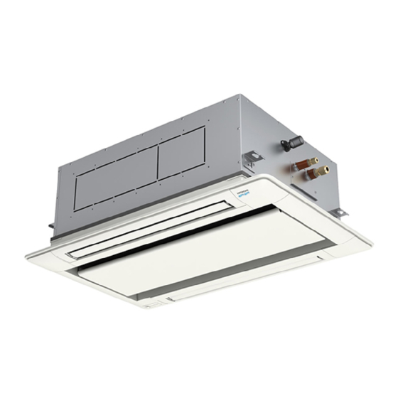
Hitachi RCD-0.8FSN3 Installation And Operation Manual
Hide thumbs
Also See for RCD-0.8FSN3:
- Service manual (382 pages) ,
- Installation and operation manual (82 pages)
Advertisement
Quick Links
INSTALLATION AND OPERATION MANUAL
MANUAL DE INSTALACIÓN Y FUNCIONAMIENTO
INSTALLATIONS- UND BETRIEBSHANDBUCH
MANUEL D'INSTALLATION ET DE FONCTIONNEMENT
MANUALE D'INSTALLAZIONE E D'USO
MANUAL DE INSTALAÇÃO E DE FUNCIONAMENTO
INSTALLATIONS- OG BETJENINGSVEJLEDNING
INSTALLATIE- EN BEDIENINGSHANDLEIDING
INSTALLATION- OCH DRIFTHANDBOK
Advertisement

Related Manuals for Hitachi RCD-0.8FSN3


Summary of Contents for Hitachi RCD-0.8FSN3
- Page 1 MANUAL DE INSTALAÇÃO E DE FUNCIONAMENTO INSTALLATION AND OPERATION MANUAL INSTALLATIONS- OG BETJENINGSVEJLEDNING MANUAL DE INSTALACIÓN Y FUNCIONAMIENTO INSTALLATIONS- UND BETRIEBSHANDBUCH INSTALLATIE- EN BEDIENINGSHANDLEIDING INSTALLATION- OCH DRIFTHANDBOK MANUEL D’INSTALLATION ET DE FONCTIONNEMENT MANUALE D’INSTALLAZIONE E D’USO...
- Page 3 English Español Deutsch Français Italiano Português Dansk Nederlands Svenska...
- Page 4 C A U T I O N P R E C A U C I Ó N V O R S I C H T A D V E R T I S S E M E N T AV V E R T E N Z E C U I D A D O A D VA S E L ! V O O R Z I C H T I G...
- Page 5 This product contains biocidal substances according to EU Reg. 528/2012 Este producto contiene sustancias biocidas según el Reg. UE 528/2012 Dieses Produkt enthält Biozide nach EU Verordnung 528/2012 Conformément à la Reg UE 528/2012, ce produit contient des substances biocides Questo prodotto contiene sostanze biocidi ai sensi del Reg.
- Page 6 INDEX INDEX PART I- OPERATION PARTIE I - FONCTIONNEMENT PART II- INSTALLATION PART II - INSTALLATION INDICE ÍNDICE PARTE I - FUNZIONAMENTO PARTE 1 - FUNCIONAMIENTO PARTE II - INSTALLAZIONE PARTE 2 - INSTALACIÓN ÍNDICE INHALTSVERZEICHNIS PARTE I - FUNCIONAMENTO TEIL I - BETRIEB PARTE II - INSTALAÇÃO TEIL II –...
- Page 7 INDHOLDSFORTEGNELSE INNEHALLSFÖRTECKNING DEL I - BETJENING PART I - ANVÄNDNING DEL II- MONTERING DEL II- INSTALLATION INHOUDSOPGAVE DEEL I- BEDIENING DEEL II: INSTALLATIE English Original version...
- Page 9 PART I- OPERATION 1 GENERAL INFORMATION 1.1 GENERAL NOTES HITACHI makes every effort to offer correct, up-to-date or transmitted in any shape or form without the permission of documentation. Despite this, printing errors cannot be controlled HITACHI Air Conditioning Products Europe, S.A.U.
- Page 10 IMPORTANT NOTICE 2.2 ADDITIONAL INFORMATION ABOUT SAFETY D A N G E R • HITACHI is not able to foresee all the circumstances which may • result in a potential danger. • • Do not pour water in the indoor or outdoor unit. These products with electric components, this will cause a serious electric •...
- Page 11 BEFORE OPERATION 4 BEFORE OPERATION C A U T I O N • • • • 4.1 EFFICIENT USE OF INDOOR UNIT • Do not leave a window or a door open • Use a circulator if warm air stays around the ceiling The comfort will be increased.
- Page 12 MAIN PARTS 5 MAIN PARTS Indoor Unit (Electrical Box Cover) Air Outlet Louver Air Panel (Optional) Air Inlet Flat Grille inside) Marked of Warning Remote Control Switch (Optional) The operating condition is displayed on the LCD. N O T E •...
- Page 13 AVAILABLE REMOTE CONTROL SWITCH 6 AVAILABLE REMOTE CONTROL SWITCH For detailed functions should be referred to remote control Installation and Operation Manual. 7 HIGH SPEED SETTING FUNCTION Ceiling height High speed setting function 0.8 to 1.5HP 2.0 to 6.0HP Speed 1 or 2 from the function selection menu depending on a Less than 2.6m Less than 3.1m Standard...
- Page 14 SIMULTANEOUS OPERATION 9 SIMULTANEOUS OPERATION Contact a distributor or a contractor for detail. 10 MAINTENANCE D A N G E R N O T E • • C A U T I O N 10.1 DAILY MAINTENANCE 10.1.1 • or neutral detergent. •...
- Page 15 MAINTENANCE • Press “ ” (menu). Remove the supporting string from the air panel. Select “Filter sign reset” from the menu and press “OK”. The • from the air panel surface. Menu 15:10(Fri) • Filter Sign Reset Elevating Grille N O T E Function 3 Simple Timer Schedule Timer...
- Page 16 TROUBLESHOOTING 11 TROUBLESHOOTING This is not abnormal Phenomenon Cause and Action All indication lamps on the remote control The micro-computer is activated to protect the device from switch are turned OFF. electromagnetic waves. Restart the operation. The operation is stopped automatically because the motion “Motion Sensor is activated”...
- Page 17 TROUBLESHOOTING Check the items before contacting a contractor. Trouble Checking Point Action Check that the main power source Turn ON the main power source for the air conditioner. is turned ON. Operation Unavailable Check that the fuse is not blown out Replace the fuse or reset the circuit breaker.
- Page 18 TROUBLESHOOTING 11.1 CONTACT DISTRIBUTOR If the problem is not resolved even after checking the previous items or if other troubles not mentioned in the previous pages occur, stop using the product and contact your distributor or contractor. C A U T I O N Trouble Action before contact The protection devices (fuse, breaker, ELB, etc) are frequently activated...
- Page 19 TROUBLESHOOTING 11.2 MAIN ALARM CODES Code Category Content of abnormality Indoor unit Outdoor unit Activation of protection device (high pressure cut) Abnormality between indoor and outdoor Transmission Abnormality between Inverter PCB and outdoor PCB Supply phase Abnormality power source phases Voltage Abnormality of voltage drop in outdoor unit Decrease in discharge gas superheat...
- Page 20 NAME OF PARTS PART II- INSTALLATION 12 NAME OF PARTS Models : RCD-0.8FSN3, RCD-1.0FSN3, RCD-1.5FSN3, RCD-2.0FSN3, RCD-2.5FSN3, RCD-3.0FSN3 Viewed from P 1100 Number Part name Number Part name Drain Discharge Mechanism Fan Motor Float Switch Drain Pan Distributor Rubber Plug for Drain...
- Page 21 NAME OF PARTS Models : RCD-4.0FSN3, RCD-5.0FSN3, RCD-6.0FSN3 Viewed from P 1660 Number Part name Number Part name Drain Discharge Mechanism Fan Motor Float Switch Drain Pan Distributor Rubber Plug for Drain Strainer Air Panel: P-AP160DNA (Optional) Air Inlet Flat Grille Air Filter Refrigerant Gas Pipe Connection (with 15.88 Flare Nut)
- Page 22 BEFORE INSTALLATION 13 BEFORE INSTALLATION 13.1 COMBINATION OF OUTDOOR UNIT AND INDOOR UNIT The combination capacity of indoor unit against the outdoor unit is selected by the outdoor unit capacity. Refer to the technical combination unit capacity. 13.2 TRANSPORTATION AND HANDLING •...
- Page 23 INDOOR UNIT INSTALLATION 14.1 FACTORY-SUPPLIED ACCESSORIES Check to ensure that the following accessories are packed with the indoor unit. The hose clamp, screws, washers and plastic clamps are put in the pipe insulation. N O T E • • Accessory Q'ty Purpose Checking scale (cut and take out it from the...
- Page 24 14.2 INITIAL CHECK 14.2.1 D A N G E R • The refrigerant R410A, charged in the HITACHI air conditioners and operation and maintenance as shown below. heat pumps, is an incombustible and non-toxic gas. However, if • maximum permissible concentration of R410A in air is 0.42 kg/m the indoor unit.
- Page 25 INDOOR UNIT INSTALLATION 14.2.2 D A N G E R • • Consider the air distribution from the indoor unit to the space down and it may lead to injuries. of the room, and select a suitable location so that uniform air •...
- Page 26 INDOOR UNIT INSTALLATION 14.3 INSTALLATION 14.3.1 14.3.3 1 Pattern Board for Installation and Scale for Dimension of Opening the indoor unit paying attention to the space for the piping, a. For installation work, the pattern board is required. The wiring and maintenance. pattern board for installation and the checking scale are 2 Then cut out the false ceiling for the indoor unit installation printed on the back side of the packing.
- Page 27 INDOOR UNIT INSTALLATION 3 Mounting Nuts and Washers 5 Adjusting Indoor Unit Position Screw nuts and washers on the suspension bolts before Adjust the position of the indoor unit with the checking scale mounting the indoor unit. as required. a. For False Ceiling with Opening N O T E When installing the indoor unit to the false ceiling with an opening, check the dimension of opening and adjust the...
- Page 28 REFRIGERANT PIPING WORK c. Ceiling Not Completed with Panels yet Check the levelness at each corner (•) of the unit with a level or by pouring water to the clear vinyl tube as shown in the When the false ceiling is not completed yet, attach the pattern board to the indoor unit with the screw (M6), 7 The upper surface of the unit is protected by corrugated cardboard to prevent the unit from being damaged by...
- Page 29 Unit: mm Correct Incorrect Correct Incorrect Model Gas Pipe Liquid Pipe RCD-0.8FSN3 Hole Hole RCD-1.0FSN3 Ø12.7 Ø6.35 Attach a cap or put a plastic bag Attach a cap or put a plastic bag RCD-1.5FSN3 over the pipe end over the pipe end RCD-2.0FSN3...
- Page 30 REFRIGERANT PIPING WORK 15.2 PIPING CONNECTION 1 Flaring Work Required tightening torque Pipe size Tightening torque below. Ø6.35 (1/4) 14 - 18 (N-m) • Flare Pipe Dimensions Ø9.52 (3/8) 34 - 42 (N-m) Ø12.7 (1/2) 49 - 61 (N-m) mm (in.) Ø15.88 (5/8) 68 - 82 (N-m) Ø...
- Page 31 DRAIN PIPING 16 DRAIN PIPING Perform drain piping work and attach the insulations before c. Attach the factory-supplied hose clamp to the vinyl tape refrigerant piping work. (white) attached to the drain hose. The hose clamp shall be 20mm away from the end face of the drain hose.
- Page 32 DRAIN PIPING f. Raising Drain Pipe 5 Drainage and Water Leakage Check In case of raising the drain pipe, install it according to After performing drain piping work and the electrical wiring and before installing the air panel, check to ensure that piping length of a+b+c shall be within 1100mm.
- Page 33 ELECTRICAL WIRING 6 Insulate the drain pipe connection and the drain hose after N O T E connecting them with gaskets. If improperly insulated, dew condensation will occur. (mm) Terminal blocks Completely wrap up to cover the transparent area of the drain pipe end connection and the hose band Hose band (Accessory) Drain-up mechanism...
- Page 34 ELECTRICAL WIRING 17.1 GENERAL CHECK 3 Check to ensure that the power supply voltage is within (main power switches, circuit breakers, wires, conduit connectors and wire terminals) have been properly selected 4 Check the capacity of the electrical wires. If the power according to the electrical data given in “Technical Catalog”.
- Page 35 ELECTRICAL WIRING 6 Perform wiring work for the indoor unit according to the 17.2.3 electrical wiring diagram and the technical documentation of the outdoor unit. D A N G E R 7 In case that power source is applied to control line. If the power source is applied to the control line (Terminal 1 and 2 •...
- Page 36 ELECTRICAL WIRING 8 Remote control switch connection d. Connecting remote control switch in case of connecting between refrigerant cycles. a. Installing remote control switch to each unit with individual operation setting Indoor unit Indoor unit Indoor unit Indoor unit Outdoor Outdoor unit unit...
- Page 37 ELECTRICAL WIRING 17.2.4 The electrical wiring capacity of the outdoor unit should be referred according to Installation and Operation Manual of the outdoor unit. Dip switch setting may be required depending on the combination with the outdoor unit. control cable length between the outdoor unit and the indoor unit shall be less than 75m. Case A Case B Remote control switch...
- Page 38 ELECTRICAL WIRING • Remote control Remote control Remote control Remote control switch (Option) switch (Option) switch (Option) switch (Option) Main switch Main switch Outdoor unit Indoor unit number 1 Indoor unit number 2 Indoor unit number 3 Indoor unit number 4 Earth wiring Power source cable...
- Page 39 ELECTRICAL WIRING Power Source Transition Remote Main Switch CB (fuse) Earth wire wire size for Total indoor control Minimum Wiring size (mm control circuit unit capacity switch cable Switch wire size length (m)*1) (n/A/mA) capacity (A) capacity (A) < 7A 2/40/30 2 Core cable 2 core twist...
- Page 40 ELECTRICAL WIRING 17.4 DIP SWITCH SETTING 1 Turn OFF all the power supply to the indoor and the outdoor Horsepower units before dip switch setting. If not, the setting is invalid. Setting position 1 2 3 4 5 6 1 2 3 4 5 6 1 2 3 4 5 6 below.
- Page 41 This air panel is applicable to the following indoor unit model. Air Panel Indoor Unit Model P-AP90DNA RCD-0.8FSN3 to 3.0FSN3 P-AP160DNA RCD-4.0FSN3 to 6.0FSN3 18.2 TRANSPORTATION AND HANDLING 1 Transport the air panel without unpacking as close to the installation location.
- Page 42 INSTALLATION OF OPTIONAL AIR PANEL P-AP(90/160)DNA 18.4 INSTALLATION C A U T I O N N O T E 1 The suspension height of the indoor unit should be referred 5 Remove the corner pocket covers. to “Installation & Maintenance Manual” of the indoor unit. The corner pocket covers can be removed pulling part 2 Do not touch the louver during the installation work.
- Page 43 INSTALLATION OF OPTIONAL AIR PANEL P-AP(90/160)DNA the air panel to the mounting seat of the unit by using long the gap between the panel and the ceiling in order to prevent air leakage may cause deformation of the inner face of the panel, but it is not abnormal.
- Page 44 INSTALLATION OF OPTIONAL AIR PANEL P-AP(90/160)DNA 18.5 ELECTRICAL WIRING 2 After completing the wiring connection of the air panel, C A U T I O N attaching work in the reverse procedure of removing. (Refer • Air panel Hinge Wiring connector for louver •...
- Page 45 TEST RUN • N O T E • • • • Do not clamp any wiring between the unit and the air panel C A U T I O N • Louver 19 TEST RUN Test run should be performed according to this manual and N O T E Installation and Operation Manual of the outdoor unit.
- Page 46 3 Perform the test run according to the “Installation and Operation Manual” of PC-ARF(PE) remote control. 20 MAIN SAFETY AND CONTROL DEVICES RCD-0.8FSN3, RCD-1.0FSN3, RCD-1.5FSN3, RCD-2.0FSN3, RCD-2.5FSN3, Model RCD-3.0FSN3, RCD-4.0FSN3, RCD-5.0FSN3, RCD-6.0FSN3...
- Page 47 Shimizu Factory, Hitachi-Johnson Controls Air Conditioning, Inc 390, Muramatsu, Shimizu-ku Shizuoka-shi. 4240926 – Japan © 2015 Johnson Controls-Hitachi Air Conditioning Technology (Hong Kong) Ltd. Printed in Japan...