Table of Contents
Advertisement
Quick Links
This Service Manual is for the CD-E99, which is a minor-modification model of the CD-E700/CD-E77, This manual, therefore,
describes only the changed points from the service manual.
Please refer to the CD-E700/CD-E77, service manual (No. S1301CDE700//) together with this manual.
CD-E700/CD-E77
REMOVING AND REINSTALLING THE MAIN PARTS .......................................................................................................... 9
ADJUSTMENT ....................................................................................................................................................................... 10
TROUBLESHOOTING ........................................................................................................................................................... 37
FUNCTION TABLE OF IC ..................................................................................................................................................... 41
FL DISPLAY .......................................................................................................................................................................... 47
IMPORTANT SERVICE NOTES ........................................................................................................................................ 2
SPECIFICATIONS ............................................................................................................................................................. 2
NAMES OF PARTS ........................................................................................................................................................... 3
DISASSEMBLY .................................................................................................................................................................. 5
NOTES ON SCHEMATIC DIAGRAM ................................................................................................................................ 8
TYPES OF TRANSISTOR AND LED ................................................................................................................................. 8
BLOCK DIAGRAM ............................................................................................................................................................. 9
SCHEMATIC DIAGRAM / WIRING SIDE OF P.W.BOARD ............................................................................................. 12
VOLTAGE ........................................................................................................................................................................ 29
WAVEFORMS OF CD CIRCUIT ...................................................................................................................................... 30
REPLACEMENT PARTS LIST/EXPLODED VIEW
All manuals and user guides at all-guides.com
SERVICE MANUAL
CONTENTS
SHARP CORPORATION
MINI COMPONENT SYSTEM
MODEL
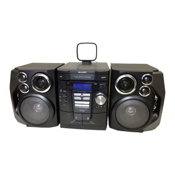
CD-E99 Mini Component System consisting of CD-E99
(main unit) and CP-E99 (speaker system).
• In the interests of user-safety the set should be restored to its
original condition and only parts identical to those specified be
used.
This document has been published to be used
for after sales service only.
The contents are subject to change without notice.
CD-E99
No. S2316CDE99///
CD-E99
Page
Page
Advertisement
Table of Contents

Related Manuals for Sharp CD-E99


Summary of Contents for Sharp CD-E99
-
Page 1: Table Of Contents
This Service Manual is for the CD-E99, which is a minor-modification model of the CD-E700/CD-E77, This manual, therefore, describes only the changed points from the service manual. Please refer to the CD-E700/CD-E77, service manual (No. S1301CDE700//) together with this manual. -
Page 2: Important Service Notes
All manuals and user guides at all-guides.com CD-E99 IMPORTANT SERVICE NOTES BEFORE RETURNING THE AUDIO PRODUCT (Fire & Shock Hazard) Before returning the audio product to the user, perform the following safety checks. 1. Inspect all lead dress to make certain that leads are not... -
Page 3: Names Of Parts
All manuals and user guides at all-guides.com CD-E99 NAMES OF PARTS CD-E99 Front panel 1. Disc Tray 2. Timer Set Indicator 3. Memory/Set Button 4. Power On/Stand-by Button 5. Clock Button 6. Timer/Sleep Button 7. Tuning and Time Up Button 8. - Page 4 All manuals and user guides at all-guides.com CD-E99 CD-E99 Remote control 1. Remote Control Transmitter 2. Disc Number Select Buttons 3. Program Clear Button 4. CD Memory Button 5. CD Track Down or Fast Reverse, Tape 2 Rewind Button 6. CD Pause Button 7.
-
Page 5: Disassembly
All manuals and user guides at all-guides.com CD-E99 DISASSEMBLY CD-E99 Caution on Disassembly Follow the below-mentioned notes when disassembling Top Cabinet the unit and reassembling it, to keep it safe and ensure Front excellent performance: (A1)x2 Panel ø3x12mm 1. Take cassette tape and compact disc out of the unit. - Page 6 All manuals and user guides at all-guides.com CD-E99 (E4)x2 (L1)x3 Loading Tray (E5)x1 (F3)x1 (E4)x1 Front Panel (F2)x1 Power PWB (E6)x1 Transformer (E1)x1 Headphones ø3x6mm (L1)x3 Main PWB (F2)x1 (E2)x1 Figure 6-4 (F1)x2 (E3)x1 ø3x10mm Protect Circuit ø3x6mm (M1)x2 ø3x10mm...
- Page 7 All manuals and user guides at all-guides.com CD-E99 CP-E99 REMOVAL PROCEDURE FIGURE STEP Passive Radiator 1. Screw ...... (A1) x4 Super Tweeter 2. Side Panel ....(A2) x1 3. Screw ...... (A3) x4 Speaker Box Woofer 1. Front Panel ..... (B1) x1 (D1)x2 2.
-
Page 8: Notes On Schematic Diagram
All manuals and user guides at all-guides.com CD-E99 NOTES ON SCHEMATIC DIAGRAM • Resistor: • The indicated voltage in each section is the one measured by Digital Multimeter between such a section and the chas- To differentiate the units of resistors, such symbol as K and M are used: the symbol K means 1000 ohm and the symbol sis with no signal given. -
Page 9: Removing And Reinstalling The Main Parts
All manuals and user guides at all-guides.com CD-E99 TO DISPLAY SECTION TO MAIN SECTION – 3 4 5 *WRQ *RES LC78646E CD SERVO XOUT CONT 5 SLDO SPDO 28 27 VCC2 +3.3V LA6574H FOCUS/TRACKING/ SPIN/SLED DRIVER LASER CONSTANT DRIVER VOLTAGE +3.3V... -
Page 10: Adjustment
All manuals and user guides at all-guides.com CD-E99 AM LOOP ANTENNA IC301 ZD351 TA7358AP ANTENNA 5.1V FM FRONT END 10.7 MHz FM IF T302 CF303 BF301 X351 450 kHz CF351 456 kHz B.P.F T351 CF352 CNP301 AM IF FM RF L312... - Page 11 All manuals and user guides at all-guides.com CD-E99 FL701 FL DISPLAY TO CD SECTION TAPE MECHANISM ASS'Y +B10 RX701 52 51 55 40 25 13 30 REMOTE SENSOR +B10 +B10 IC701 VLOAD AVDD IX0553AW SYSTEM SW701-SW707 SW711-SW718 MICROCOMPUTER SW721-SW724 (1/2)
-
Page 12: Schematic Diagram / Wiring Side Of P.w.board
All manuals and user guides at all-guides.com CD-E99 CNS601 BI601 R-CH FM SIGNAL R601 A_GND PLAYBACK SIGNAL L-CH R602 CD_GND RECORD SIGNAL CD_+B CD SIGNAL IC601 D_GND C653 C601 LC75341 220P 220/16 LD+7V VIDEO SIGNAL AUDIO PROCESSOR LD+7V C609 R605... - Page 13 All manuals and user guides at all-guides.com CD-E99 MAIN PWB-A1(1/3) R693 C602 C653 C601 0.022 220P 220/16 L-CH R691 C691 SSOR 6.8K 390P JK690 VIDEO/AUX R690 C690 6.8K 390P R603 R-CH R692 C603 VREF 22/50 C608 C610 0.12 1/50 ROUT...
- Page 14 All manuals and user guides at all-guides.com CD-E99 C302 0.001 AM TRACKING C331 C330 0.047 C323 0.022 (UJ) C332 0.022 C338 0.001 T303 D301 DS1SS133 AM ANTENNA C342 D302 DS1SS133 0.022 VD301 T306 SVC348S C335 AM OSC. 560P R358 (HB) 3.9K...
- Page 15 All manuals and user guides at all-guides.com CD-E99 MAIN PWB-A1 (2/3) C373 TP302 0.015 C371 1/50 R350 2.7K R358 C367 3.9K 1/50 C372 1/50 10 11 R352 R353 R355 C357 T351 3.3K 2.2/50 AM IF C356 0.001 R393 L352 C389 0.001...
- Page 16 All manuals and user guides at all-guides.com CD-E99 IC901 STK41243 – POWER AMP. L902 C913 3µH 100P C907 R903 100P Q903 KTC3199 GR R917 0.1(3W) ZD902 ZD903 R918 DZ12BSB DZ12BSB C917 1.5K 0.01(ML) C916 C918 R905 100/50 100/50 R925 R926...
- Page 17 All manuals and user guides at all-guides.com CD-E99 MAIN PWB-A1 (3/3) FM SIGNAL L902 3µH CNS971 99 GR R942 680(2W) M901 R943 680(2W) FAN MOTOR – R945 R944 1.5K 1.5K L1_OUT D912 R949 DS1SS133 HEADPHONES R1_OUT PWB-A3 C931 R950 R947...
- Page 18 All manuals and user guides at all-guides.com CD-E99 FL701 LED A PWB-A4 FL DISPLAY LED DRIVER BI703 +10V Q710 R794 KRC102 M 45 44 43 42 41 40 39 38 37 36 35 34 33 32 31 30 29 28 27 26 25 24 23 22 21 20 19 18 17 16 15 14 13 12 11 10 9...
- Page 19 All manuals and user guides at all-guides.com CD-E99 DISPLAY PWB-A2 18 17 16 15 14 13 12 11 10 9 R795 C701 1/50 C702 220/10 87 88 89 90 91 92 93 94 95 96 97 R763 –20dBATT DSA_STB R702...
- Page 20 All manuals and user guides at all-guides.com CD-E99 CD SERVO PWB-C CD SIGNAL PICKUP UNIT HPC1LX VREF VREF 1.2K 8.2K 8.2K 0.047(ML) 80 79 78 77 76 75 74 47/25 8.2K SLCO CNP1 SLCIST EFMIN 0.001 RFVDD 0.022 0.0027 RSVSS...
- Page 21 All manuals and user guides at all-guides.com CD-E99 CD RES 100P 100P 100P 100P 0.022 4.7K CLAMP SW O/C, 2.2K 1.2K 2.2K DISC NO CNP6 80 79 78 77 76 75 74 73 72 71 70 69 68 67 66...
- Page 22 All manuals and user guides at all-guides.com CD-E99 MAIN PWB-A1 COLOR TABLE BROWN R374 C302 R378 RD(R) R373 X352 R372 ORANGE R388 C382 R359 YELLOW IC302 R376 C395 R379 GREEN C381 C387 R360 BLUE C392 L351 VIOLET R377 C394 C380...
- Page 23 All manuals and user guides at all-guides.com CD-E99 P26 4 - A P25 12 - D TO CD SERVO PWB TO DISPLAY PWB CNP5 CNP701A FFC701 R136 P27 10 - F CNS601 1 2 3 4 5 6 7 8...
- Page 24 All manuals and user guides at all-guides.com CD-E99 DISPLAY PWB-A2 LED B PWB-A5 SW722 RX701 EQUALIZER SW721 X-BASS/DEMO RD19 RD20 CNS704 R763 FL701 R702 C701 C702 CNP704 XL701 R705 R708 CNS701 C721 C704 R709 C705 R710 RD10 R769 R713 R716...
- Page 25 All manuals and user guides at all-guides.com CD-E99 LED A PWB-A4 BI703 CNS703 CNP703 IC701 R746 R751 R747 R735 R770 R772 SW701 R734 3 2 1 R758 POWER R731 R749 R764 Q710 R732 R730 R729 SW711 R711 R727 R761 R712...
- Page 26 All manuals and user guides at all-guides.com CD-E99 P24 1 - D P23 8 - A FROM DISPLAY PWB FROM MAIN PWB CNS701 CNS601 CD SERVO PWB-C 12 11 1 2 3 4 5 6 7 8 9 10 1 2 3 4 5 6 7 8...
- Page 27 All manuals and user guides at all-guides.com CD-E99 P30 3 - F TAPE MECHANISM TO DISPLAY PWB ASSEMBLY CNP702 TAPE MECHANISM PWB-F FFC702 SOLENOID SOLENOID TAPE MOTOR TAPE 2 TAPE 1 RECORD/PLAYBACK PLAYBACK HEAD ERASE HEAD HEAD CD LOADING MOTOR PWB-E...
- Page 28 All manuals and user guides at all-guides.com CD-E99 POWER PWB-B1 P23 12 - G P24 1 - D FROM MAIN PWB FROM DISPLAY PWB CNS801 FW701 R841 IC854 D853 CNP802 3 2 1 D801 D856 R844 10 9 8 7 6 5 4 3 2 1...
-
Page 29: Voltage
All manuals and user guides at all-guides.com CD-E99 VOLTAGE IC101 IC601 IC701 PIN NO. VOLTAGE PIN NO. VOLTAGE PIN NO. VOLTAGE PIN NO. VOLTAGE PIN NO. VOLTAGE PIN NO. VOLTAGE 7.59 V 1.6 V 4.85 V 1.0 V 4.78 V 4.93 V... -
Page 30: Waveforms Of Cd Circuit
All manuals and user guides at all-guides.com CD-E99 WAVEFORMS OF CD CIRCUIT Stopped Stopped 1999/04/07 09:51:15 CH1=500 mV CH3=500 mV 500 ms/div CH1=200 mV CH2=500 mV 500 ms/div DC 10:1 DC 10:1 (500 ms/div) DC 10:1 DC 10:1 (500 ms/div) - Page 31 CD-E99 PARTS GUIDE MINI COMPONENT SYSTEM CD-E99 MODEL CD-E99 Mini Component System consisting of CD-E99 (main unit) and CP-E99 (speaker system). “HOW TO ORDER REPLACEMENT PARTS” To have your order filled promptly and correctly, please furnish the For U.S.A. only following information.
- Page 32 All manuals and user guides at all-guides.com CD-E99 PRICE PRICE DESCRIPTION PARTS CODE DESCRIPTION PART CODE RANK RANK TRANSFORMERS CD-E99 1 PT801 RTRNP0489AWZZ J BH Power INTEGRATED CIRCUITS 1 PT841 RTRNP0483AWZZ J AL Power T301 RCILB0065AWZZ AC OSC,FM VHILC78646E-1 AY CD Servo,LC78646E...
- Page 33 All manuals and user guides at all-guides.com CD-E99 PRICE PRICE DESCRIPTION PART CODE PARTS CODE DESCRIPTION RANK RANK AB 22 µF,50V,Electrolytic AA 0.0022 µF,16V C125,126 VCEAZA1HW226M J C611,612 VCTYMN1CX222K J AA 0.022 µF,16V AB 1 µF,50V,Electrolytic C127,128 VCTYPA1CX223K C613,614 VCEAZA1HW105M J AA 0.0033 µF,16V...
- Page 34 All manuals and user guides at all-guides.com CD-E99 PRICE PRICE DESCRIPTION PARTS CODE DESCRIPTION PART CODE RANK RANK R24,25 VRD-MN2BD222J AA 2.2 kohms,1/8W R395 VRD-MN2BD473J AA 47 kohms,1/8W R26,27 VRD-MN2BD103J AA 10 kohm,1/8W R601~603 VRD-ST2CD102J AA 1 kohm,1/6W R28,29 VRD-ST2CD222J AA 2.2 kohms,1/6W...
- Page 35 All manuals and user guides at all-guides.com CD-E99 PRICE PRICE DESCRIPTION PART CODE PARTS CODE DESCRIPTION RANK RANK R907 VRD-MN2BD563J AA 56 kohms,1/8W FL701 VVKNA09SS29-1 AX FL Display R908 VRD-MN2BD102J AA 1 kohm,1/8W FW701 QCNWN2467AWZZ J AC Flat Wire,6Pin R909...
- Page 36 All manuals and user guides at all-guides.com CD-E99 PRICE PRICE DESCRIPTION PARTS CODE DESCRIPTION PART CODE RANK RANK 201-10 JKNBZ0924AWSA AK Button,Operation B LANGT0042AWFW J AC Bracket,PWB Support 201-11 JKNBZ0925AWSA AL Button,Function PCOVQ7004AWFW J AK Cover,Fan 201-12 JKNBZ0926AWSA AE Button,X-BASS/Equalizer...
-
Page 37: Troubleshooting
All manuals and user guides at all-guides.com CD-E99 CD-E99 306-2 306-1 306-3 703x2 305x2 PWB-D Figure 6 CD MECHANISM EXPLODED VIEW – 6 –... - Page 38 All manuals and user guides at all-guides.com CD-E99 CD-E99 601x2 BELT CONNECTION 202-1 FF/REW Tape FF/REW PWB-A1 ROLLER Motor ROLLER ASS'Y ASS'Y 604x2 PWB-G FLYWHEEL FLYWHEEL ASS'Y ASS'Y MAIN BELT TAPE2 TAPE1 IC851 621x2 601x2 Silicon IC852 Grease IC853 615x3...
- Page 39 All manuals and user guides at all-guides.com CD-E99 CD-E99 602x2 622x2 MECHANISM 602x2 PWB-E PWB-C 623x2 Figure 8 CABINET EXPLODED VIEW (2/2) – 8 –...
- Page 40 All manuals and user guides at all-guides.com CD-E99 CP-E99 SP5, 6 SUPER TWEETER SP7, SUPER TWEETER SP5, SP3, 4 SUPER TWEETER TWEETER SP3, Capacitor SP7, 8 TWEETER 1.8 µF, C1, C2 SUPER TWEETER Capacitor 250 V 1.8 µF, 250 V...
-
Page 41: Function Table Of Ic
All manuals and user guides at all-guides.com CD-E99 PACKING OF THE SET Setting position of switches and knobs Tape Mechanism STOP SPEAKER CP-E99 UNIT CD-E99 SPAKP0032AWZZ SSAKH0053AWZZ Polyethylene Bag,Unit Polyethylene Bag, Speaker SPAKA0431AWZZ Packing Add., Left/Right S I D S I D... - Page 42 All manuals and user guides at all-guides.com CD-E99 — M E M O — – 11 –...
- Page 43 All manuals and user guides at all-guides.com CD-E99 — M E M O — – 12 –...
- Page 44 All manuals and user guides at all-guides.com CD-E99 © COPYRIGHT 2003 BY SHARP CORPORATION ALL RIGHTS RESERVED. No part of this publication may be reproduced, stored in a retrieval system, or transmitted in any form or by any means, electronic, mechanical, photocopying, recording, or otherwise, without prior written permission of the publisher.