Carrier COMFORT SYSTEM 33CS Operating Manual
Comfort vvt system, monitor thermostat with timeclock, zone controller
Hide thumbs
Also See for CARRIER COMFORT SYSTEM 33CS:
Advertisement
Quick Links
Monitor Thermostat With Timeclock
NOTE TO INSTALLER
This manual should be left with the equipment owner.
GENERAL
This manual will assist you in using your Carrier Comfort
System thermostat. There are 2 basic types of thermostats
that you may encounter. They are called the monitor ther-
mostat and the zone controller.
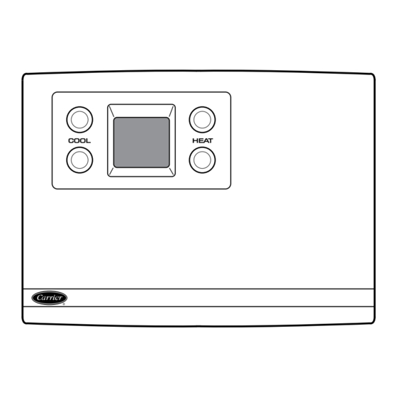
The monitor thermostat can be identified by the system
switches (FAN, HEAT, COOL) which are located along the
bottom edge of the front cover. The monitor thermostat can
be equipped with or without a timeclock. The timeclock dis-
play is located in the upper right corner of the monitor ther-
mostat. The monitor thermostat display is located in the up-
per left corner. The set point and programming buttons are
located around the display.
The zone controller does not have system switches or a
timeclock. The zone controller display is located in the up-
per left corner of the zone controller. The set point and pro-
gramming buttons are located around the display.
Manufacturer reserves the right to discontinue, or change at any time, specifications or designs without notice and without incurring obligations.
Book 1
4
PC 111
Tab
11a 13a
A Guide To Operating
Your VVT System
Catalog No. 809-247
Printed in U.S.A.
Carrier Comfort System
Zone Controller
There are three typical operations you may perform on
your VVT (variable volume and temperature) system
thermostat:
• change set points for heating and cooling
• override the unoccupied schedule
• change occupancy schedules
NOTE: Your ability to perform these functions may be lim-
ited by the security access level function which is config-
ured by the installer. If ''access denied'' is shown on the dis-
play screen, you are not allowed to access that function.
The monitor thermostat and zone controller are part of a
VVT system. The VVT system allows a single-zone heating/
cooling unit to operate as a multiple-zone system. The con-
ditioned space is divided into zones. Each comfort zone is
monitored by a zone controller. The monitor thermostat moni-
tors the operation of its own zone and of each associated
zone controller and determines system operation from in-
formation received from each device that it controls.
Form VVT-2SO
Pg 1
33CS
VVT System
10-95
Replaces: New
Advertisement

Related Manuals for Carrier CARRIER COMFORT SYSTEM 33CS


Summary of Contents for Carrier CARRIER COMFORT SYSTEM 33CS
- Page 1 NOTE TO INSTALLER This manual should be left with the equipment owner. GENERAL This manual will assist you in using your Carrier Comfort System thermostat. There are 2 basic types of thermostats that you may encounter. They are called the monitor ther- mostat and the zone controller.
- Page 2 OPERATION Electronic Timeclock (Monitor Thermostat Only) — To set the clock, remove the cover of the thermostat. Two buttons, located under the timeclock, are provided to set the clock. They are labeled select and adjust. Press the select button. The minutes setting on the clock will flash. Press the adjust button until the correct minutes are shown.
-
Page 3: Occupancy Schedule
Occupancy Schedule — The occupancy schedule es- tablishes the time periods when the monitor thermostat and zone controller operate in the occupied or unoccupied mode. The unoccupied/occupied schedule has individual 7-day programming with 8 time periods. Unoccupied/occupied ON/ OFF times are entered on the minute. The start of an ON time is the beginning of the occupied mode. - Page 4 Copyright 1995 Carrier Corporation Manufacturer reserves the right to discontinue, or change at any time, specifications or designs without notice and without incurring obligations. Book 1 PC 111 Catalog No. 809-247 Printed in U.S.A. Form VVT-2SO Pg 4 10-95 Replaces: New...
Need help?
Do you have a question about the CARRIER COMFORT SYSTEM 33CS and is the answer not in the manual?
Questions and answers