
Summary of Contents for Sigicom INFRA D10
- Page 1 INFRA D10 INFRA D10 Micro Datalogger Art no. 080-05010-0 Art no. 080-05030-0 Manual ver. C Valid for firmware 1.2.0 Copyright © Sigicom AB 2020 Art.no. ML089-05010-0En...
-
Page 2: Table Of Contents
1.5. Unpacking and Parts Identification ........... 7 Safety instructions ................8 2.1. INFRA D10 Li-Ion battery............8 2.2. INFRA D10 Micro Lead Acid battery ........9 Recycling ..................10 Product Description ................10 4.1. Keypad ..................10 4.2. Display ..................11 4.3. - Page 3 6.10. Disable Communication ............36 6.11. Time Synchronization through Internet ........37 6.12. Daylight Saving Time ............. 37 6.13. INFRA Net Remote Control ........... 37 6.13.1. Force Reboot ............... 38 6.14. Firmware Upgrade ..............39 Copyright © Sigicom AB 2020...
- Page 4 Appendix A. Battery Level Limits ............44 Appendix B. Li-Ion Battery Transport ............ 46 Appendix C. Battery removal and installation ........47 Appendix D. Mounting and transportation of INFRA D10 Micro ..49 Appendix E. Errors and Warnings ............51 Copyright © Sigicom AB 2020...
-
Page 5: Introduction
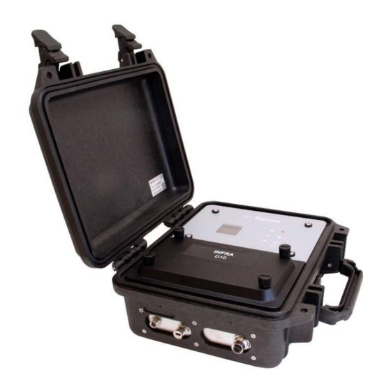
1.2. INFRA D10 Datalogger INFRA D10 is a digital datalogger replacing the older INFRA Master/Mini. It is compatible with all bus cable connected sensors of the INFRA system. Monitoring data is buffered on the memory card and is sent when the next cellular communication takes place. -
Page 6: Monitoring Logic
The static sensors (X20) cannot produce transients. Their trigger levels are only used to make a connection to the INFRA Net server which then can send a message about the event. See the manual for each sensor you are using Copyright © Sigicom AB 2020... -
Page 7: Unpacking And Parts Identification
Sigicom. Keep record of the instrument’s serial number. You will be asked to give this number in any communication you may have with Sigicom related to this product. Copyright © Sigicom AB 2020... -
Page 8: Safety Instructions
2. Safety instructions For mounting instructions for INFRA D10 Micro, see Appendix D. For battery removal and installation instructions, see Appendix C. 2.1. INFRA D10 Li-Ion battery • Only Sigicom B100 batteries are allowed to be used in INFRA •... -
Page 9: Infra D10 Micro Lead Acid Battery
A worn-out battery, a battery with cracks or with signs to be swollen or leaking should be replaced immediately. • The INFRA D10 Micro shall be mounted upright with the battery standing at the bottom of the enclosure. • The battery strap included with the INFRA D10 Micro shall be used to secure the battery. -
Page 10: Recycling
This equipment falls under the Waste Electrical and Electronic Equipment Directive (WEEE directive) 2012/19/EU, category 9: monitoring and control instruments, and should be handled accordingly. Sigicom uses a certified local partner for recycling of scrapped equipment. The batteries used in this equipment falls under the Battery Directive 2006/66/EC: •... -
Page 11: Display
Menu / Enter / Acknowledge For more information about operation of the graphical user interface, see chapter 6 Operation. 4.2. Display A color display is used to show data and status. Here is the Main screen: Copyright © Sigicom AB 2020... -
Page 12: Infra D10 Batteries
COMMUNICATION status. ERRORS and WARNINGS See chapter 6 for more information. 4.3. INFRA D10 Batteries D10 is powered by two Li-Ion batteries. The battery with the highest voltage is always the active one, and the switch-over between the batteries is automatic. -
Page 13: Memory Card
Master/Mini/Micro. Please contact Sigicom Support for guidance regarding memory card formatting or other memory card issues. Note! Only use a memory card delivered by Sigicom, see section 8 Accessories. 4.5. SIM Cards If activated when ordering, the embedded SIM card (eSIM) is used. This is soldered on the main circuit board for robustness. - Page 14 Note! APN must be set when using inserted mini-SIM card, see section 5.1.3. Note! Sigicom cannot ensure that all third-party SIM cards are compatible with this product. Please order the mini-SIM card with no PIN code lock.
- Page 15 Figure 3. The location of mini-SIM slot on D10. The mini-SIM can be accessed in a similar fashion on the D10 Micro. Copyright © Sigicom AB 2020...
-
Page 16: External Power Connector
Note! D10/D10 Micro is never powered through the USB connector. Use the plastic cap to protect the USB connector when not in use. The reason for not charging them higher is to extend battery life time. Copyright © Sigicom AB 2020... -
Page 17: Configuration And Installation
Configuration for INFRA Net communication 5.1.1. INFRA Net customers using eSIM will get a pre-set customer account from Sigicom prior to delivery. To make the INFRA Net communication to work, three files shall be configured in the config directory of the memory card: •... - Page 18 After the phone number, the recipient’s name can be entered. Examples of SMS recipients in the config-file smsdest.txt: 070545262626 # Henry (Data messages only) A+467021343556 # Mary (All messages) S+497051343559 # Rose (Service messages only) /070135565335 # John (No messages) Copyright © Sigicom AB 2020...
-
Page 19: Setting A Non-Default Apn For A Mini-Sim Card
Remote live and Agenda 5.1.4. The Remote live function is used together with Agenda to continuously receive Interval values during some hours a day, for example during office hours. Please contact Sigicom support for further information. Other configuration files 5.1.5. •... -
Page 20: Sensor Network
This is enabled by placing a file named busrate.txt in the config directory which first row must be: slow Copyright © Sigicom AB 2020... - Page 21 If only one node shall be connected, and if a cable of 5 meter or shorter is to be used, a direct connection can be made, see Figure 5. Figure 5. Example of a small INFRA sensor network Copyright © Sigicom AB 2020...
- Page 22 The sensor S50 also uses more power than the other sensor types, which gives some special limitations also here: Distance between Maximum number of S50 and D10/D10 S50 sensors Micro 0 – 120 m 120 – 180 m 180 – 250 m More than 250 m Copyright © Sigicom AB 2020...
-
Page 23: Startup Check
• INFRA Net communication, see section 6.5.2 • That the internal date and time is correct; otherwise see Clock Set, section 6.9.3 • Possible errors and warnings, select Errors in the Menu, see section 6.8 Copyright © Sigicom AB 2020... -
Page 24: Operation
Power off – if Monitoring is off, D10/D10 Micro will do an automatic power off after some minutes. Error codes, if present, will be indicated at bottom right on the main screen and should be checked up before monitoring is started. See section 6.8.6. Copyright © Sigicom AB 2020... -
Page 25: Start Monitoring
. This is indicated by the monitoring symbol which turns to gray. D10/D10 Micro will then communicate to INFRA Net and update its new status and data. In older versions of the INFRA system, Monitoring is called registration (REGON and REGOFF, respectively). Copyright © Sigicom AB 2020... -
Page 26: Infra Net Communication
Automatic INFRA Net Communication 6.5.1. Automatic communication will be done in the following situations: • After start or stop of monitoring. • After a transient recording. • Scheduled upload. • When an error has been detected. Copyright © Sigicom AB 2020... -
Page 27: Manual Infra Net Communication
“Comm details”, with further communication and legal information. Use keys to scroll through this information: • SIM card info. • Modem info. • Cell network info. • Legal info. Copyright © Sigicom AB 2020... -
Page 28: Automatic Power Off
If power was accidentally lost while in monitoring mode (e.g. if the batteries were improperly removed), D10/D10 Micro will restart monitoring when charged batteries are inserted. 6.8. GUI Menu The graphical user interface (GUI) menu is reached by pressing from the main screen: Copyright © Sigicom AB 2020... -
Page 29: Node Config
Note! When changing standard, it is important to check all node parameters such as Interval time, Record time and Trigger level, because each standard has its own setting of those parameters. The recommended way to configure the monitoring parameters is to use INFRA Net. Copyright © Sigicom AB 2020... -
Page 30: Node Info
A yellow or red triangle at the bottom right of the main screen indicates that an error code is set. For viewing and possibly resetting an error code, select Errors in the GUI menu, and press Copyright © Sigicom AB 2020... -
Page 31: Settings And Actions
D10/D10 Micro. No data files will be lost and can be uploaded later. Upload schedule 6.9.2. This is the screen which presents the list of hours a schedule is set. It is also possible to add or remove hours to/from the list. Copyright © Sigicom AB 2020... -
Page 32: Clock Set
Note! D10 will reboot automatically after the clock is changed. Clock format 6.9.4. Time can be displayed in either 12- or 24-hour format, which is configured by this selection. This configuration is only for the instrument, INFRA Net is not affected by this. Copyright © Sigicom AB 2020... -
Page 33: Alarm Beacon X85
If a value is above the alarm setting, the relay of the X85 will be activated. 2. Beacon duration, which decides how long time the alarm is active. Copyright © Sigicom AB 2020... -
Page 34: Usb Mode
See section 6.14 for a detailed explanation how to upgrade to the latest FW version. Display off 6.9.8. From the main screen, the display can be turned off manually by pressing followed by . Monitoring will not be stopped by this. Copyright © Sigicom AB 2020... -
Page 35: Power Off And Reboot
Note! Monitoring must be OFF when doing power off or reboot. Select either power off or reboot in the list and click . If the selected action is permitted, you will be asked to confirm once again with Copyright © Sigicom AB 2020... -
Page 36: Gui Passcode
→ Settings and actions → GUI Passcode. 6.10. Disable Communication Flight mode means that all communication is disabled and is configured by removing or renaming the file ftpserver.txt in the config directory of the memory card. Copyright © Sigicom AB 2020... -
Page 37: Time Synchronization Through Internet
D10/D10 Micro does not communicate automatically when monitoring is off. When communicating with INFRA Net, D10/D10 Micro sends its status and parameter settings. On the Hardware tab in INFRA Net, you can view Copyright © Sigicom AB 2020... -
Page 38: Force Reboot
It is possible to force a reboot (= restart) on an D10/D10 Micro which is monitoring. This is done by selecting (in INFRA Net – Hardware tab) Special commands → Force Reboot followed by Manage changes → Commit. D10/D10 Micro will perform the reboot at the next communication. Copyright © Sigicom AB 2020... -
Page 39: Firmware Upgrade
6.14. Firmware Upgrade This section describes how to upgrade the latest FW version which is available for download from the Sigicom Support page: http://support.sigicom.com/infra. Note! Monitoring must be OFF to perform a firmware upgrade. This is the procedure: Set the D10/D10 Micro in USB mode (see section 6.9.6, step 1 to Copy the new firmware (a .bin file and a .meta file) to the file... -
Page 40: Technical Specifications
INFRA Net communications. Backup battery: Expected life > 5 years. Note! The Backup battery may only be replaced by Sigicom. Modem: Cellular (2G, 3G and 4G) modem. Operations temp: -20°C to +50°C (-4°F to 122°F) -
Page 41: Accessories
Battery charger Li-Ion B50/B100, art.no. 080-01628-0 • Lead-Acid battery cable, art.no. 080-01610-1 • Power supply C2x (EU), art.no. 080-01682-0, valid for outdoor use. See latest INFRA product catalogue for a complete list of accessories, and more details of these. Copyright © Sigicom AB 2020... -
Page 42: Maintenance And Calibration
If the backup battery drops below 2.6 V, a warning message will be communicated. For replacement of the backup battery, send the instrument to Sigicom. • If repair is required, please contact Sigicom prior to sending the instrument in for repair. • No calibration of the D10/D10 Micro is needed. -
Page 43: Contact And Support
Phone: +46 8 44 99 770 Email: support@sigicom.com Sweden: Sigicom AB Glasfibergatan 8 SE-125 45 ÄLVSJÖ Phone: +46 8 4499750 Email: info@sigicom.com USA: Sigicom Inc. 2649 E. Mulberry, Unit No. 17 Fort Collins, CO 80524 Phone: 970-493-1552 Email: info@sigicom.com Copyright © Sigicom AB 2020... -
Page 44: Appendix A. Battery Level Limits
And for D10 Micro: Voltage 12.7 V 100% 11.3 V 11.1 V 10.9 V The battery symbol in the display has different colors, which vary according to: Falling voltage: Display symbol BAT FULL => BAT NORMAL green scale Copyright © Sigicom AB 2020... - Page 45 If the SOC level of the two batteries differs more than 15%, the warning “UNBALANCED” will be set (D10 only). Service messages are sent when the SOC level falls below the BAT LOW or BAT CRITICAL levels. For replacement of the backup battery, send the instrument to Sigicom. Copyright © Sigicom AB 2020...
-
Page 46: Appendix B. Li-Ion Battery Transport
The shipper is always responsible for the transport and its documentation. Regulations are updated annually or more frequently. For more information about shipping and travelling with Li-Ion batteries, please see Sigicom Support page. Transport of D10 with batteries installed: •... -
Page 47: Appendix C. Battery Removal And Installation
• Remove the lower front panel by unscrewing the knurled screws. • Carefully, insert Sigicom B100 batteries into the battery holders • If batteries are to be replaced, one battery at the time can be replaced to keep the unit running while the replacement is done. - Page 48 Attach the strap to hold the battery in-place • Connect the short special cable to one of the connectors of the longer battery cable • Start the D10 Micro and check the state of charge of the battery Copyright © Sigicom AB 2020...
-
Page 49: Appendix D. Mounting And Transportation Of Infra D10 Micro
(254mm * 375mm, 10.0” * 14.8”). For easy installation it is recommend using expanding screws (or anchor bolts) on the wall so that you can first hang the unit and then use washers and nuts to secure it. Copyright © Sigicom AB 2020... - Page 50 If the cable lead-through on the bottom of the D10 Micro is to be used, slice the insert according to the picture below. When re-mounting the screw nut, screw until the cable is firmly in place and not sliding when pulling lightly. Then screw another half turn. Copyright © Sigicom AB 2020...
-
Page 51: Appendix E. Errors And Warnings
E110 File system failure Check the memory card E145 Node lost This error can be triggered only when monitoring is on. Connect all sensor and restart D10. E146 Incomplete config Contact Sigicom support Copyright © Sigicom AB 2020...
Need help?
Do you have a question about the INFRA D10 and is the answer not in the manual?
Questions and answers