Table of Contents
Advertisement
Quick Links
Advertisement
Table of Contents

Related Manuals for Pepperl+Fuchs IUH-F190-V1 Series


Summary of Contents for Pepperl+Fuchs IUH-F190-V1 Series
- Page 1 FACTORY AUTOMATION MANUAL IUH-F190-V1-* Read / Write Head for IDENTControl...
- Page 2 IUH-F190-V1-* With regard to the supply of products, the current issue of the following document is ap- plicable: The General Terms of Delivery for Products and Services of the Electrical Indus- try, published by the Central Association of the Electrical Industry (Zentralverband Elektrotechnik und Elektroindustrie (ZVEI) e.V.) in its most recent version as well as the supplementary clause: "Expanded reservation of proprietorship"...
-
Page 3: Table Of Contents
IUH-F190-V1-* Introduction................. 6 Certificates and approvals............7 Declaration of Conformity (R&TTE Directive 1995/5/EC)....7 FCC Information ................... 7 IC Information..................8 UL Information..................8 Additional country-specific approvals..........8 Safety ................... 9 Symbols relevant to safety..............9 Intended Use ..................9 General notes on safety .............. - Page 4 IUH-F190-V1-* Countries of Use.................17 4.3.1 European Union ................17 4.3.2 Argentina..................17 4.3.3 Australia ................... 17 4.3.4 Brazil ....................18 4.3.5 Canada .................... 18 4.3.6 China....................18 4.3.7 Hong Kong ..................18 4.3.8 India ....................19 4.3.9 Japan ....................19 4.3.10 Colombia..................
- Page 5 IUH-F190-V1-* Mounting ..................... 28 5.3.1 Room Orientation................29 5.3.2 Minimum Distances ................. 30 5.3.3 Polarization ..................30 Connection ..................31 EMC Concept..................31 Commissioning................. 32 Definitions................... 32 6.1.1 Display..................... 32 6.1.2 Legend..................... 32 Initial Commissioning................ 33 Device Settings .................. 34 Operation via the Command Interface ..........
-
Page 6: Introduction
Introduction Introduction Congratulations You have chosen a device manufactured by Pepperl+Fuchs. Pepperl+Fuchs develops, produces and distributes electronic sensors and interface modules for the market of automation technology on a worldwide scale. Before you install this device and put it into operation, please read the operating instructions thoroughly. -
Page 7: Certificates And Approvals
Note! A Declaration of Conformity can be requested from the manufacturer or downloaded from www.pepperl-fuchs.com. The product manufacturer, Pepperl+Fuchs GmbH, 68307 Mannheim, has a certified quality assurance system that conforms to ISO 9001. ISO9001 FCC Information FCC ID: IREIUH-F190-V1 This device complies with Part 15 of the FCC Rules. -
Page 8: Ic Information
Nominal power supply voltage is 24 V . For the intended use this read/write head has to be connected to Pepperl+Fuchs IDENTControl control interfaces using a shielded connection cable. The IDENTControl supplies the read/write head with 20 ... 30 V , Protective Extra Low Voltage (PELV). -
Page 9: Safety
Read through these instructions thoroughly. Familiarize yourself with the device before installing, mounting, or operating. Pepperl+Fuchs GmbH provides no guarantee that the information contained in this document does not contain third-party industrial property rights. Pepperl+Fuchs GmbH does not issue any licenses to its own or third-party patents or other industrial property rights in this document. -
Page 10: General Notes On Safety
If serious faults occur, stop using the device. Secure the device against inadvertent operation. In the event of repairs, return the device to your local Pepperl+Fuchs representative or sales office. The connection of the device and maintenance work when live may only be carried out by a qualified electrical specialist. -
Page 11: Product Description
IUH-F190-V1-* Product Description Product Description RFID Frequency Bands The following diagram shows the position of the different frequency bands used for RFID. The IUH-F190-V1-* read/write heads described in this manual operate in the frequency range from 865 MHz ... 868 MHz and from 902 MHz ... 928 MHz, highlighted in color. 1000 10000 Frequency... -
Page 12: Memory Structure Of A Tag / Epc Gen 2 (Iso/Iec 18000-63)
IUH-F190-V1-* Product Description 4.2.3 Memory Structure of a Tag in Accordance with EPC Gen 2 (ISO/IEC 18000-63) [7:0] DSFID [7:0] Commands Read / write head Memory module [15:0] SR/ER Bank 11 USER [31:16] SW/EW Bank 10 SF/EF SS/ES Bank 01 UII/EPC SP/EP Optional XPC_W2... - Page 13 IUH-F190-V1-* Product Description Bank 00: Password Management The segment Bank 00 contains the password management information, comprising the access password and the kill password. The read/write head manages the kill password with the standard read/write commands SW and SR. The access password is not supported. See "Single Read Words SR"...
-
Page 14: Electronic Product Code (Epc)
IUH-F190-V1-* Product Description 4.2.4 Electronic Product Code (EPC) The electronic product code is a unique identifier in the form of a sequence of numbers. The number sequence has a set structure and a length of 64 bits, 80 bits, 96 bits, or longer (depending on the EPC Ident number used). -
Page 15: Dense Reader Mode (Drm)
IUH-F190-V1-* Product Description 100 % 90 % 80 % 70 % 60 % 50 % 40 % 30 % 20 % Foam material Film 10 % Cardboard (dry) Cardboard (wet) Wood (dry) Glass Metal Material underground Material between transponder and read / write head 4.2.6 Dense Reader Mode (DRM) -
Page 16: Frequency Hopping Spread Spectrum
IUH-F190-V1-* Product Description 4.2.7 Frequency Hopping Spread Spectrum With FHSS (Frequency Hopping Spread Spectrum), the information to be transmitted is distributed successively through multiple channels. Only one frequency channel is used at any one time. This results in a larger bandwidth for the entire signal, in spite of the fact that each channel has a smaller bandwidth. -
Page 17: Countries Of Use
IUH-F190-V1-* Product Description Countries of Use Note! Country Identifier All IUH-F190-V1-* read/write heads operate within their maximum frequency range with the appropriate settings for the relevant country. You must set the correct country identifier when commissioning for the first time. See chapter 6.2. Note! If you wish to use the IUH-F190-V1-* read/write head in a country not included in this chapter, make sure the relevant values for the read/write head are consistent with the local conditions... -
Page 18: Brazil
IUH-F190-V1-* Product Description Number of channels: 12 ■ Channels used: 1, 2, 3, ... 12 Center frequencies: 919.75 MHz + (M x 0.5) MHz All 12 channels are always used. 4.3.4 Brazil In Brazil, the use of RFID in the UHF range is regulated as follows: UHF wavelength: 915 MHz …... -
Page 19: India
IUH-F190-V1-* Product Description 4.3.8 India In India, the use of RFID in the UHF range is regulated in accordance with EN 302208. UHF wavelength: 865 MHz … 867 MHz ■ Radiated power: 30 mW … 300 mW ; Default = 50 mW (IUH-F190-V1-FR1) ■... -
Page 20: Mexico
IUH-F190-V1-* Product Description Number of channels: 8 ■ Channels used: 1, 2, 3, ... 8 Center frequencies: 918.75 MHz + (M x 0.5) MHz All 8 channels are always used. 4.3.12 Mexico The regulations for the UHF frequency range in Mexico meet the requirements for the UHF frequency range in the U.S.. -
Page 21: South Korea
IUH-F190-V1-* Product Description Channel spacing: 200 kHz ■ Frequency access method: programmable frequency list ■ Number of predefined channels: 10 ■ Programmable channels: 1, 2, 3, ... 10 Center frequencies: 866.1 MHz, 866.3 MHz, 866.5 MHz, 866.7 MHz, 866.9 MHz, 867.1 MHz, 867.3 MHz, 867.5 MHz, 867.7 MHz, 867.9 MHz Up to 10 channels can be parameterized and used in sequence. -
Page 22: United States Of America
IUH-F190-V1-* Product Description Number of channels: 10 ■ Channels used: 1, 2, 3, ... 10 Center frequencies: 919.75 MHz + (M x 0.5) MHz All 10 channels are always used. 4.3.18 United States of America In the USA, the use of RFID in the UHF range is regulated in accordance with the Federal Communications Commission (FCC) Rules. -
Page 23: General Functions And Features
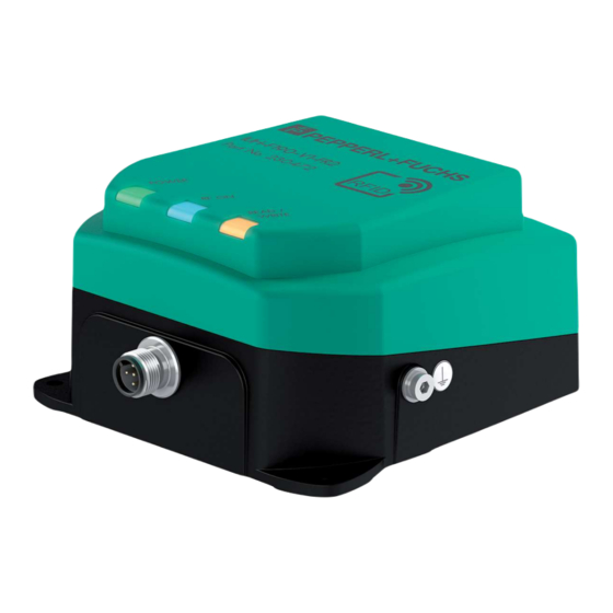
IUH-F190-V1-* Product Description General Functions and Features IUH-F190-V1-EU Figure 4.5 IUH-F190-V1-FR* Figure 4.6 Functions The read/write head was developed for reading and writing passive read/write tags with an ultra-high operating frequency. Measurement Range The measurement range is typically 1 meter. Tags that comply with EPC Gen 2 (ISO/IEC 18000-63) are supported. -
Page 24: Indicators And Operating Controls
IUH-F190-V1-* Product Description Integrated Antenna The IUH-F190-V1-EU read/write head has a fully circular polarized antenna. The IUH-F190-V1-FR1 and the IUH-F190-V1-FR2 read/write head have a linear dual polarized antenna. The read/write heads can transmit and receive waves with horizontal, vertical, and circular polarization. -
Page 25: Scope Of Delivery
IUH-F190-V1-* Product Description Scope of Delivery Read/write head ■ Quick start guide ■ Accessories 4.8.1 IDENTControl The read/write head can be connected to Pepperl+Fuchs IDENTControl control interfaces. Interface Designation 4 read/write heads: Ethernet IC-KP-B17-AIDA1 2 read/write heads: PROFIBUS IC-KP2-2HB6-V15B Ethernet... -
Page 26: Read/Write Tags
IUH-F190-V1-* Product Description 4.8.2 Read/Write Tags Type Designation EPC Gen 2 (ISO/IEC 18000-63) IUC72-F151-M-FR1 IUC72-F152-M-FR1 IUC72-F152-M-FR2 IUC76-50-M-FR1 IUC76-50-M-FR2 IUC76-50-FR1 IUC76-50-FR2 IUC76-F157-M-FR1 IUC76-F157-M-FR2 IUC76-F203-M-FR1 IUC76-F203-M-FR2 IUC76-C8-T14-GBL IUC77-F151-M-GBL IUC77-25L100-GBL IUC77-25L110-GBL Table 4.2 4.8.3 Connection cable for R/W heads and trigger sensors Compatible connection cables with shielding are available for connecting the R/W heads and trigger sensors. -
Page 27: Cable Connectors For The Power Supply
IUH-F190-V1-* Product Description 4.8.4 Cable connectors for the power supply Compatible M12 sockets with an open cable end for connecting the IDENTControl to a power supply are available in different lengths. Figure 4.9 Accessories Designation Length 2 m (straight socket) V1-G-2M-PUR Length 5 m (straight socket) V1-G-5M-PUR... -
Page 28: Installation
■ Retain the original packaging in case you have to store or ship the device again at a later date. Should you have any questions, please contact Pepperl+Fuchs. Mounting The read/write head is intended for wall mounting or mounting on brackets in internal areas. -
Page 29: Room Orientation
IUH-F190-V1-* Installation Mounting the Read / Write Head Figure 5.1 5.3.1 Room Orientation The alignment of the read/write tag antennae in relation to the antennae of the read/write head influences the detection range of the system. Make sure the antennae are aligned parallel to each other. -
Page 30: Minimum Distances
IUH-F190-V1-* Installation 5.3.2 Minimum Distances When positioning the read/write head, please observe the minimum distances. The lateral distance between the read/write head and metals or liquids should be at least 50 cm. The distance between the read/write head and the ground should be at least 50 cm. metal support Figure 5.2 During simultaneous operation of several read/write heads, only one read/write head may ever... -
Page 31: Connection
IUH-F190-V1-* Installation Figure 5.3 = Vertical polarization plane = Horizontal polarization plane Note! You cannot switch the polarization on the IUH-F190-V1-EU read/write head. This read/write head has an almost circular polarized antenna. Owing to its small size, the antenna polarization is not perfectly circular, but elliptical. -
Page 32: Commissioning
IUH-F190-V1-* Commissioning Commissioning Definitions 6.1.1 Display Angle brackets contain the abbreviated meaning of a command structure, e.g., <Data> The index or .xx denotes a hexadecimal number. denotes a value in the hexadecimal system, specified in ASCII characters. ASCII Example: 10 corresponds to A corresponds to 41 . -
Page 33: Initial Commissioning
IUH-F190-V1-* Commissioning <WordAddr>: Word start address in the read/write tag, 4 hex characters, range ASCII from "0000h" to "FFFF", depending on tag type <WordNum>: Number of words to be read or written, 2 hex characters. Range ASCII from "01" through "20" depending on the tag type, word lengths are 4 bytes Initial Commissioning All IUH-F190-V1-* read/write heads operate within their maximum frequency range from 865... -
Page 34: Device Settings
IUH-F190-V1-* Commissioning Country Identifiers for IUH-F190-V1-FR2 Country Occupied Frequency Bandwidth Identifier Frequency Access Method Country or Region 902 MHz ... 928 MHz United States Frequency hopping spread spectrum Canada Mexico Argentina Colombia 920 MHz ... 925 MHz China Frequency hopping spread spectrum 915 MHz ... - Page 35 IUH-F190-V1-* Commissioning Example: In the examples below, the read/write head is connected to channel 1 of the control interface. The outputs follow the multiframe protocol, see table "Responses Depending on Protocol Mode QV" on page 55. Reading the Country Identifier Read Parameter RC Use the read parameter RC command to read out the read/write head's country identifier: Serial...
- Page 36 IUH-F190-V1-* Commissioning Serial Ethernet PROFIBUS/PROFINET Response: .30.31.00.0E.30. .00.20.1D.03.00.0D.00.0E. .1D.03.00.0D.00.0E.30.00. 00.30.14.F7.33.7 30.00.30.14.F7.33.7C.00.1 30.14.F7.33.7C.00.1F.00.0 C.00.1F.00.00.00 F.00.00.00.00.01.00.08.E2 0.00.00.01.00.08.E2.00.60 .00.01.00.08.E2. .00.60.03.14.42.D6.D1 .03.14.42.D6.D1 00.60.03.14.42.D 6.D1 Table 6.4 Enhanced read read-only code, tag is entering the measurement range Describing Tags Single Write Special Read-Only Code Send the single write special read-only code command to the read/write head while a tag is in the measurement range.
- Page 37 IUH-F190-V1-* Commissioning Parameterizing the Read/Write Head Requesting and Setting the Transmission Power Read out the read/write head's transmission power with the read parameter PT command: Serial Ethernet PROFIBUS/PROFINET Command: RP1UPT.00.00 .00.0A.BE.03.00.55.50.54. .BE.03.00.55.50.54.00.00 00.00 Confirmation: .00.06.BE.03.FF.33 .BE.03.FF.33 Response: .30.31.00.32 .00.0A.BE.03.00.34.00.02. .BE.03.00.34.00.02.00.32 00.32 The read/write head's set transmitting power is 50 mW (32 corresponding to 50...
-
Page 38: Operation
IUH-F190-V1-* Operation Operation General The sections below contain information about the commands that relate to the read/write head IUH-F190-V1-*. The commands are described using the example of an IDENTControl control interface with serial interface. All other generally applicable commands and error or status messages can be found in the manual for your IDENTControl control interface. -
Page 39: Command Overview
IUH-F190-V1-* Operation Read Algorithm To communicate with tags with the maximum possible probability, the read/write head uses an algorithm that varies the transmitting power and frequency. You can set the corresponding values for this algorithm via the parameters Power Transmit (PT), Channel Frequency (CD), or Number of Channels (NC) for the frequency hopping spread spectrum, and Number of Attempts (TA). -
Page 40: Read/Write Commands
IUH-F190-V1-* Operation Configuration Commands Abbreviation Command description See "Read Parameters" on page 49 See "Write Parameters" on page 49 Read/Write Commands The tag's memory structure is based on the following read/write commands in accordance with EPC Gen 2 (ISO/IEC 18000-63). See chapter 4.2.3. Single Read Read-Only Code SF One attempt is made to read a read-only code (TID). - Page 41 IUH-F190-V1-* Operation Note! UII/EPC If there are multiple tags in the measurement range with the same UII/EPC, the identical tags are reported with Status A. Enhanced Read Special Read-Only Code ES This command continuously attempts to read the UII segment from tags according to EPC Gen2 (ISO/IEC 18000-63).
- Page 42 IUH-F190-V1-* Operation When using this command, make sure that the protocol control word contains the correct length of the following UII/EPC. If this is not executed correctly, the complete data is not output on the subsequent read operation because the command SS uses the length in the protocol control word for the output.
- Page 43 IUH-F190-V1-* Operation Example: ER1000101 continuously reads a 4-byte word from memory address "0001". Note! The memory bank (MB) parameter defines the bank accessed by this command. see "Memory Module for Tag Accesses to the "Memory Bank" MB" on page 52. Single Write Words SW One attempt is made to write <WordNum>...
-
Page 44: Filter Commands
IUH-F190-V1-* Operation Kill UHF Tag KI This command sets a UHF tag to a state where no further access is possible. The command can be executed only if a valid password has previously been set in segment Bank 00 via the command SW. - Page 45 IUH-F190-V1-* Operation Meaning of Bits Command Command <ChanNo> Channel 1 <FilterNumber> First filter used, filter number = 0 <MemBank> Memory bank 01; should be filtered to UII/EPC <Negate> Not negated <LogicalOperation> OR link not relevant here because only one filter is set Value is always 0 <StartAddress>...
- Page 46 IUH-F190-V1-* Operation Activate/Deactivate Filter MF Command MF activates or deactivates the filter masks. Command: MF<ChanNo><Value><CHCK><ETX> Response: <Status><ChanNo><CHCK><ETX> The following values are possible: 0 = Deactivate filter masks 1 = Activate filter masks - mode 1 2 = Activate filter masks - mode 2 Example: MF11 activates the filter masks for IDENTControl channel 1 Command MF - Mode 1...
-
Page 47: Configuration Commands
IUH-F190-V1-* Operation If a write command is executed next, all tags in the measurement range that are not "B" tags are selected. These tags are assigned a 'Selected' flag. The write command is executed only for tags with no Selected flag. When the filter is set to "B,"... -
Page 48: Read And Write Parameters
IUH-F190-V1-* Operation Note! The IUH-F190-V1-* read/write head uses only tag type 80. Tag Types, UHF Chip UII / User Pepperl+Fuchs Bank 00 data type Type Designation designation [bit] [bit] Type Unique? [byte] EPC Class 1 NXP UCode- IUC72 32 + 32... - Page 49 IUH-F190-V1-* Operation Parameter is readable/writeable Abbre- viation Page IUH-F190-V1-EU IUH-F190-V1-FR* See "Number of Channels NC" on Readable/writeable for RC = 2, 3, 7, 9, 10, 11, page 53 12, 13, 14 Readable for RC = 1, 4, 5, 6, 8 See "Search Algorithm Cancellation Readable/writeable Readable/writeable...
-
Page 50: Parameters
IUH-F190-V1-* Operation 7.6.3 Parameters Antenna Polarization AP This parameter switches polarization to horizontally linear/vertically linear/circular or reads out the currently set polarization. ParamTyp: Default: AP = R Value range: R = Right-handed circular H = Horizontally linear V = Vertically linear Example: WP1UAP.00.01H switches the polarization to horizontally linear WP1UAP.00.01R switches the polarization to right-handed circular... - Page 51 IUH-F190-V1-* Operation Status 0 and status A depend on this parameter, and are output immediately. ParamTyp: Default: E5 = 5 Value range: 0 ... 252 Example: WP1UE5.00.01.05 sets the number to 5 unsuccessful read/write attempts until a status 5 is output RP1UE5.00.00 outputs the number If the number of read/write attempts is reduced:...
- Page 52 IUH-F190-V1-* Operation The information type , RSSI value , tag access to transmission channel 13 .00.14 , transmission power 20 mW Memory Module for Tag Accesses to the "Memory Bank" MB This parameter specifies the bank accessed by the read/write commands SR, ER, SW, and EW.
- Page 53 IUH-F190-V1-* Operation Example: If the country identifier RC = 01 (= 4 channels), RP1UMF.00.00 returns the response 01.63.64.67.65 Explanation of the response: <Status> = 0 <ChanNo> = 1 <PCh04> = .63 = 99 results in 99 - 100 = -1 dBm <PCh07>...
- Page 54 Parameter QV toggles the output protocol between single frame and multiframe. In single-frame protocol, the output corresponds to the Pepperl+Fuchs standard in LF and HF systems. If there is more than one tag in the measurement range, status A is output as a warning.
- Page 55 IUH-F190-V1-* Operation If QV = M, the following responses are made to a single read command (SR): Response: 0<ChanNo><Luii><UII1><Ldata><data><CHCK><ETX> 0<ChanNo><Luii><UII2><Ldata><data><CHCK><ETX> 0<ChanNo><Luii><UII3><Ldata><data><CHCK><ETX> F<ChanNo>0003<CHCK><ETX> One read command was executed to which three tags responded. For each tag, the status, the IDENTControl channel, the length of the UII, the UII, the length of the data, and the read data are output.
- Page 56 IUH-F190-V1-* Operation Q Value QW In accordance with EPC Gen 2 (ISO/IEC 18000-63), the slotted ALOHA principle is used for anticollision. The number of time slots is defined as 2 . The parameter QW defines the Q value. As a guide, the number of time slots should roughly correspond to the number of expected tags in the measurement range.
- Page 57 IUH-F190-V1-* Operation The serial response .30.31.80.02 indicates the country identifier for the IUH-F190-V1-FR2-02, which is set by the manufacturer. You cannot change this country identifier. Reset to Default, RD This parameter returns all settings of the read/write head to the default configuration. The parameter RC remains unchanged.
-
Page 58: Error/Status Messages
IUH-F190-V1-* Operation Number of Attempts "Tries Allowed" TA This parameter sets the permitted number of write or read attempts, or outputs the permitted number of attempts. ParamTyp: Default: TA = 2 Value range: 1 ... 255 Example: WP1UTA.00.01.01 permits precisely one attempt (= no repeats) WP1UTA.00.01.03 permits 3 attempts RP1UTA.00.00 outputs the permitted number of attempts If the permitted number of write or read attempts between the read/write head and the tag is... -
Page 59: Service And Maintenance
IUH-F190-V1-* Service and Maintenance Service and Maintenance The device is designed and constructed to function stable over long periods of time. For this reason, regular cleaning or maintenance is unnecessary. -
Page 60: Troubleshooting
IUH-F190-V1-* Troubleshooting Troubleshooting Problem Solution Interference from several Change the setting of the transmission channels ■ read/write heads in the Reduce the transmission power local vicinity ■ Status A message Check whether there are multiple tags in the detection range: ■... -
Page 61: Appendix
IUH-F190-V1-* Appendix Appendix 10.1 Dimensions IUH-F190-V1-EU ø4 (3x) Figure 10.1 IUH-F190-V1-FR* ø4 (3x) Figure 10.2 10.2 ASCII table ASCII ASCII ASCII hex ASCII Space " &... -
Page 62: Detection Range
IUH-F190-V1-* Appendix ASCII ASCII ASCII hex ASCII < > 10.3 Detection Range The read/write head has a typical detection range of around 1 meter; this range is determined by the tag used and can be adjusted by selecting the transmission power. Other influencing factors include the design/installation of the specific application, interference from any materials present (in particular metal), and the ambient conditions. - Page 63 IUH-F190-V1-* Appendix A list of all available documents is displayed. Antenna Diagram The antenna diagrams show the electric field strength in the far field depending on the direction. The front of the read/write head points towards 0°. IUH-F190-V1-FR2 Horizontal cut -180 0 dB -150...
- Page 64 IUH-F190-V1-* Appendix Vertical cut -180 0 dB -150 -3 dB -6 dB -9 dB -12 dB -120 -15 dB -18 dB -21 dB -24 dB -27 dB -30 dB 1.Read/write head points towards 0° Figure 10.4 - Horizontal polarization - Vertical polarization - Circular polarization with linear tag - Full width at half maximum...
- Page 65 IUH-F190-V1-* Appendix...
- Page 66 Twinsburg, Ohio 44087 · USA Tel. +1 330 4253555 E-mail: sales@us.pepperl-fuchs.com Asia Pacific Headquarters Pepperl+Fuchs Pte Ltd. Company Registration No. 199003130E Singapore 139942 Tel. +65 67799091 E-mail: sales@sg.pepperl-fuchs.com www.pepperl-fuchs.com Subject to modifications / DOCT2945F Copyright PEPPERL+FUCHS • Printed in Germany 11/2014...
Need help?
Do you have a question about the IUH-F190-V1 Series and is the answer not in the manual?
Questions and answers