Makita LS1018 Instruction Manual
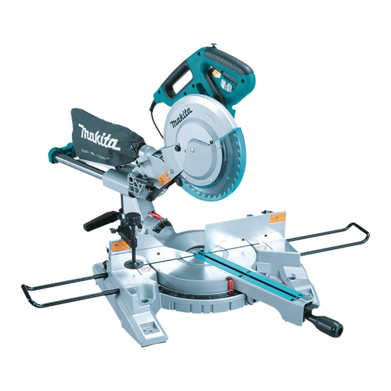
Slide compound miter saw
Hide thumbs
Also See for LS1018:
- Instruction manual (132 pages) ,
- Instruction manual (8 pages) ,
- Instruction manual (61 pages)

Related Manuals for Makita LS1018


Summary of Contents for Makita LS1018
- Page 1 INSTRUCTION MANUAL Slide Compound Miter Saw LS1018 LS1018L LS1018L GBA DOUBLE INSULATION Read before use.
-
Page 2: Specifications
SPECIFICATIONS Model: LS1018 LS1018L / LS1018L GBA Blade diameter 255 - 260 mm Hole diameter Countries other than Europe 25.4 mm or 30 mm (country specific) European countries 30 mm Max. kerf thickness of the saw blade 3.2 mm Max. miter angle Right 60°, Left 47°... -
Page 3: Ec Declaration Of Conformity
Avoid body contact with earthed or grounded NOTE: The declared noise emission value(s) has surfaces, such as pipes, radiators, ranges and been measured in accordance with a standard test refrigerators. There is an increased risk of elec- method and may be used for comparing one tool with tric shock if your body is earthed or grounded. -
Page 4: Safety Instructions For Mitre Saws
Do not let familiarity gained from frequent use Keep handles and grasping surfaces dry, clean of tools allow you to become complacent and and free from oil and grease. Slippery handles and ignore tool safety principles. A careless action can grasping surfaces do not allow for safe handling and cause severe injury within a fraction of a second. - Page 5 Do not reach behind the fence with either hand 18. After finishing the cut, release the switch, hold closer than 100 mm from either side of the saw the saw head down and wait for the blade to stop blade, to remove wood scraps, or for any other before removing the cut-off piece.
-
Page 6: Installation
12. Be careful not to damage the arbor, flanges (espe- When the tool is shipped, the handle is locked in the cially the installing surface) or bolt. Damage to lowered position by the stopper pin. Release the stop- these parts could result in blade breakage. per pin by simultaneously applying a slight downward pressure on the handle and pulling the stopper pin. -
Page 7: Functional Description
Do not remove spring holding blade guard. If guard becomes damaged through age or UV light exposure, contact a Makita service center for a new guard. DO NOT DEFEAT OR REMOVE GUARD. Positioning kerf board ►... - Page 8 Maintaining maximum cutting capacity This tool is factory adjusted to provide the maximum cutting capacity for a 255 mm saw blade. Unplug the tool before any adjustment is attempted. When installing a new blade, always check the lower limit position of the blade and if necessary, adjust it as follows: ►...
-
Page 9: Adjusting The Bevel Angle
Stopper arm Adjusting the bevel angle ► 1. Stopper arm 2. Adjusting screw ► 1. Lever The lower limit position of the blade can be easily To adjust the bevel angle, loosen the lever at the rear of the tool adjusted with the stopper arm. -
Page 10: Switch Action
A switch in need of repair may result in unintentional operation and serious personal injury. Return tool to a Makita service center for proper repairs BEFORE fur- ther usage. -
Page 11: Electronic Function
Laser line is factory adjusted so that it is positioned Electronic function within 1 mm from the side surface of the blade (cutting position). Soft start feature NOTE: • When laser line appears dim and hard to see This function allows the smooth start-up of the tool by because of direct sunlight, relocate the work limiting the start-up torque. - Page 12 5. Shaft lock • Use only the Makita socket wrench provided Press the shaft lock to lock the spindle and use the to install or remove the blade.Failure to use the socket wrench to loosen the hex bolt clockwise. Then wrench may result in overtightening or insufficient remove the hex bolt, outer flange and blade.
- Page 13 Connecting a vacuum cleaner When you wish to perform clean cutting operation, connect a Makita vacuum cleaner. ► 1. Blade case 2. Arrow 3. Arrow 4. Saw blade To install the blade, mount it carefully onto the spindle, making sure that the direction of the arrow on the sur- face of the blade matches the direction of the arrow on the blade case.
-
Page 14: Securing Workpiece
Securing workpiece WARNING: • Before operating the tool, make sure that the WARNING: sliding fence is secured firmly. • Before bevel-cutting, make sure that no part • It is extremely important to always secure of the tool, especially the blade, contacts the the workpiece correctly with the proper type fence when fully lowering and raising the of vise or crown molding stoppers. - Page 15 Horizontal vise (optional accessory) ► 1. Sub-fence R 2. Screws The sub-fence R can be removed from the right side of ► 1. Vise plate 2. Vise nut 3. Vise knob the guide fence. To remove the sub-fence R, loosen the screw which secures the sub-fence R and pull it out.
-
Page 16: Operation
OPERATION WARNING: • Firmly tighten the knob clockwise so that the carriage will not move during operation. NOTICE: Insufficient tightening of the knob may cause • Before use, be sure to release the handle from the possible kickback which may result in serious lowered position by pulling the stopper pin. -
Page 17: Compound Cutting
3. Miter cutting CAUTION: Refer to the previously covered "Adjusting the • Always remove the sub-fence R so that it does miter angle". not interfere any part of the carriage when per- forming right bevel cuts. 4. Bevel cut 5. Compound cutting Compound cutting is the process in which a bevel angle is made at the same time in which a miter angle is being cut on a workpiece. - Page 18 In the case of right bevel cut Table (A) Bevel angle Miter angle Molding position in 52/38° type 45° type 52/38° type 45° type Fig. A Right 31.6° Right 35.3° For inside corner Right 33.9° Right 30° Left 31.6° Left 35.3° For outside corner Right 31.6°...
-
Page 19: Groove Cutting
9. Groove cutting ► 1. Aluminum extrusion 2. Guide fence 3. Spacer block 4. Horizontal vise (optional accessory) ► 1. Cut grooves with blade When securing aluminum extrusions, use spacer A dado type cut can be made by proceeding as blocks or pieces of scrap as shown in the figure to follows: prevent deformation of the aluminum. -
Page 20: Carrying Tool
Carrying tool Adjusting the cutting angle This tool is carefully adjusted and aligned at the factory, but rough handling may have affected the alignment. If your tool is not aligned properly, perform the following: 1. Miter angle Make sure that the tool is unplugged. Secure the blade at 0°... - Page 21 ► 1. Screw 2. Pointer 3. Miter scale ► 1. Triangular rule 2. Saw blade 3. Top surface of turn table Make sure that the pointer points to 0° on the miter scale. If the pointer does not point to 0°, loosen Carefully square the side of the blade with the top the screw which secures the pointer and adjust surface of the turn base using the triangular rule, try-...
-
Page 22: Optional Accessories
Center. • Steel & Carbide-tipped saw blades (Refer to our website or contact your local Makita Remove and check the carbon brushes regularly. dealer for the correct saw blades to be used for Replace when they wear down to 3 mm in length. Keep the material to be cut.) - Page 24 Makita Europe N.V. Jan-Baptist Vinkstraat 2, 3070 Kortenberg, Belgium Makita Corporation 3-11-8, Sumiyoshi-cho, Anjo, Aichi 446-8502 Japan LS1018L- ENEU-1803 www.makita.com 20181106...