
Related Manuals for DoorHan PCB-SL

Summary of Contents for DoorHan PCB-SL
- Page 1 Content ReMote ContRoLLeR PRoGRAMMInG CONTROL BOARD PCB-SL Actual versions pcb - v 1.0 soft - v 1.0 Programming instructions board PCB-SL © DoorHan, 2016...
-
Page 2: Table Of Contents
1.3. Description of terminals of control unit ........................4 1.4. DIP-switches adjustment .............................. 5 1.5. Description of mechanically operated controls ......................5 2. REMOTE CONTROLLER PROGRAMMING ..........................6 2.1. Cleaning of the receiver’s memory ..........................6 2.2. Record of DoorHan remote controllers in the receiver ....................6 2.3. R emote programming for Doorhan remote controllers ....................6 2.4. Marking of Doorhan remote controllers buttons ......................6... -
Page 3: Electrical Interfaces
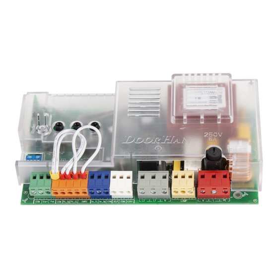
InteRFACeS 1. ELECTRICAL INTERFACES 1.1. Wiring diagram of control unit WARNING! Switch off the power before operating with control board. Always install power cables apart from signal ones. Use a braided shield cable to reduce induces noise. The wires in the cable shall be protected from contact with any rough and sharp details. Fuse 2 Connecting photocells to close. Set the jumper to NC when using photocells PhotoCell (DoorHan) Receiver LED3 Timer W Auto CL Force Fuse Connecting photocells to open. Set the jumper to NC when using photocells PhotoCell Capacitor (DoorHan) Jumpers Limit switches LED3 Observe the polarity External control button 1.2. Description of elements of control unit... -
Page 4: Description Of Terminals Of Control Unit
eLeCtRICAL InteRFACeS Control unit LEDs LEDs in bold type indicate the state when the door is stopped in the middle position. Function Motor power supply A (red) Record of remote controller code B (yellow) Failure (emergency) START command PED command Photocells to close Do not respond Respond Photocells to open Do not respond Respond STOP STOP command Limit switch to close Does not respond Responds Limit switch to open Does not respond Responds 1.3. Description of terminals of control unit 1. -
Page 5: Dip-Switches Adjustment
ELECTRICAL INTERFACES 5. Photo Op — contacts to connect safety devices to open (NC). These connections are used to protect the door leaf when opening. Operation of the devices reslts in immediate stop. Operation of the devices connected to these terminals has no effect on operation during the door closing. -
Page 6: Remote Controller Programming
ReMote ContRoLLeR PRoGRAMMInG 2. REMOTE CONTROLLER PROGRAMMING 2.1. C leaning of the receiver’s memory. After power is on, hold down the record button for remote controllers (CODE) for 10 seconds. Indicator “A” will be constantly on, warning light will flash, then indicator “B” will be on for one second and go out to confirm erasing of stored codes, warning light and indicator “A” will go out. 2.2. R ecord of DoorHan remote controllers in the receiver. To record remote controllers, press and hold down the record button for remote controllers (CODE) for 3 seconds. Press twice the selected button (you later want to control the drive operation) within 10 sec when indicator “A” is on. Indicator “B” will flash once and go out to confirm successful record of code of remote controller in the receiver’s memory, warning light and indicator “A” will go out. Note: • repeat the recording procedure for each new remote controller to set up some remote controllers. - Page 8 We very much appreciate that you have chosen the product manufactured by our company and believe that you will be satisfied with its quality. For information on purchasing, distribution and servicing contact DoorHan central office at: Kralovsky VRCH 2018, Kadan, 43201, Czech Republic Telephone: +420 474 319 111 E-mail: europe@doorhan.com www.doorhan.cz...
Need help?
Do you have a question about the PCB-SL and is the answer not in the manual?
Questions and answers