Table of Contents
Advertisement
Advertisement
Table of Contents

Related Manuals for Asus Z97-C


Summary of Contents for Asus Z97-C
- Page 1 Z97-C...
- Page 2 INCIDENTAL, OR CONSEQUENTIAL DAMAGES (INCLUDING DAMAGES FOR LOSS OF PROFITS, LOSS OF BUSINESS, LOSS OF USE OR DATA, INTERRUPTION OF BUSINESS AND THE LIKE), EVEN IF ASUS HAS BEEN ADVISED OF THE POSSIBILITY OF SUCH DAMAGES ARISING FROM ANY DEFECT OR ERROR IN THIS MANUAL OR PRODUCT.
-
Page 3: Table Of Contents
Contents Safety information ...................... vi About this guide ......................vii Z97-C specifications summary ................. ix Package contents ..................... xiii Installation tools and components ................. xiv Chapter 1: Product Introduction Special features..................1-1 1.1.1 Product highlights................ 1-1 1.1.2 5X Protection................1-2 1.1.3... - Page 4 ..........3-41 ..............3-43 ............. 3-44 Monitor menu ................... 3-44 Boot menu ....................3-48 Tool menu ....................3-54 3.9.1 ASUS EZ Flash 2 Utility ............3-54 ............3-55 3.9.3 ASUS SPD Information ............. 3-56 3.10 Exit menu ....................3-57 3.11 Updating BIOS ..................
- Page 5 Creating a RAID driver disk without entering the OS ....5-7 ® ..............5-8 5.2.2 Creating a RAID driver disk in Windows 5.2.3 Installing the RAID driver during Windows ® OS installation ..5-8 Appendices Notices ........................A-1 ASUS contact information ..................A-4...
-
Page 6: Safety Information
Safety information Electrical safety before relocating the system. When adding or removing devices to or from the system, ensure that the power cables for the devices are unplugged before the signal cables are connected. If possible, disconnect all power cables from the existing system before you add a device. Before connecting or removing signal cables from the motherboard, ensure that all power cables are unplugged. -
Page 7: About This Guide
Refer to the following sources for additional information and for product and software updates. ASUS website The ASUS website (www.asus.com) provides updated information on ASUS hardware and software products. Optional documentation that may have been added by your dealer. These documents are not part of the... - Page 8 Conventions used in this guide To ensure that you perform certain tasks properly, take note of the following symbols used throughout this manual. DANGER/WARNING: Information to prevent injury to yourself when trying to complete a task. CAUTION: Information to prevent damage to the components when trying to complete a task IMPORTANT: Instructions that you MUST follow to complete a task.
-
Page 9: Z97-C Specifications Summary
* Hyper DIMM support is subject to the physical characteristics of individual CPUs. Please refer to Memory QVL (Qualified Vendors List) for details. ** Refer to www.asus.com for the Memory QVL (Qualified Vendors List). 1 x PCI Express 3.0/2.0 x16 slot (at x16 mode) 1 x PCI Express 2.0 x16 slot* (max. - Page 10 - ASUS Enhanced DRAM Overcurrent Protection - Short circuit damage prevention - ASUS ESD Guards - Enhanced ESD protection - ASUS High-Quality 5K-Hour Solid Capacitors - 2.5x long lifespan with excellent durability - ASUS Stainless Steel Back I/O - 3x more durable corrosion-resistant...
- Page 11 Z97-C specifications summary ASUS Exclusive Features - ASUS USB 3.0 Boost featuring speedy USB 3.0 transmission - ASUS Disk Unlocker featuring 3TB+ HDD support - ASUS AI Charger - ASUS GPU Boost, 2-level GPU Boost switch - ASUS AI Suite 3...
- Page 12 CPU fan installed and switches to the control mode automatically. 64 Mb Flash ROM, UEFI AMI BIOS, PnP, DMI2.7, WfM2.0, SM BIOS 2.8, ACPI 5.0, Multi-language BIOS, ASUS EZ Flash 2, CrashFree BIOS DRAM SPD (Serial Presence Detect) memory information WfM 2.0, DMI 2.7, WOL by PME, PXE...
-
Page 13: Package Contents
Package contents Check your motherboard package for the following items 2 x Serial ATA 6 Gb/s cables ASUS Z97-C Series motherboard User manual 1 x ASUS I/O Shield Support DVD vary with different models. xiii... -
Page 14: Installation Tools And Components
Installation tools and components Intel ® LGA1150 CPU ® Intel LGA1150 compatible CPU Fan Philips (cross) screwdriver SATA hard disk drive PC chassis DIMM 1 bag of screws Power supply unit SATA optical disc drive (optional) Graphics card The tools and components in the table above are not included in the motherboard package. -
Page 15: Chapter 1: Product Introduction
SATA Express provides faster data transfer speeds of up to 6 Gb/s, allowing your system to catch up with the speed of the SSDs. It also features backward compatibility with up to two SATA drives of the same speed. ASUS Z97-C... -
Page 16: Protection
ASUS HomeCloud ASUS HomeCloud creates a world without boundaries. It lets you access your PC remotely, stream multimedia content to wherever you want, and manage all your stuff from anywhere- no matter where it’s stored. Use the built-in Wake on WAN feature to remotely wake and control your PC with a single smart device, anywhere and anytime. -
Page 17: Other Special Features
1.1.4 Other special features ErP Ready The motherboard is European Union’s Energy-related Products (ErP) ready, and ErP consumptions. This is in line with ASUS vision of creating environment-friendly and energy- product and thus mitigate environmental impacts. Motherboard overview 1.2.1 Before you proceed Take note of the following precautions before you install motherboard components or change any motherboard settings. -
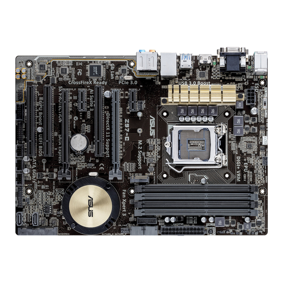
Page 18: Motherboard Layout
21.8cm(8.6in) I II KBMS_USB78 CPU_FAN CHA_FAN2 GPU_LED DIGI +VRM EATX12V MemOK! DRAM_LED HDMI 1442K LGA1150 USB3_56 LAN_USB3_34 AUDIO CHA_FAN1 PCIEX1_1 Z97-C Intel I218V CHA_FAN3 PCIEX16_1 PCI1 ® Intel 1083 PCIEX1_2 BATTERY PCIEX16_2 Super BIOS PCI2 SATA6G_1 USB1314 PCI3 CLRTC SPDIF_OUT... - Page 19 16. USB 2.0 connectors (10-1 pin USB910; USB1112; USB1314) 1-20 17. TPM connector (20-1 pin TPM) 1-17 18. Serial port connector (10-1 pin COM) 1-18 19. Digital audio connector (4-1 pin SPDIF_OUT) 1-17 20. Front panel audio connector (10-1 pin AAFP) 1-18 ASUS Z97-C...
-
Page 20: Central Processing Unit (Cpu)
Contact your retailer immediately if the PnP cap is missing, or if you see any damage to the PnP cap/socket contacts/motherboard components. ASUS will shoulder the cost of repair only if the damage is shipment/ transit-related. -
Page 21: System Memory
(DIMM) slots. A DDR3 module is notched differently from a DDR or DDR2 module. DO NOT install a DDR or DDR2 memory module to the DDR3 slot. I II Z97-C Z97-C 240-pin DDR3 DIMM sockets Recommended memory configurations ASUS Z97-C... - Page 22 Memory configurations sockets. excess memory from the higher-sized channel is then mapped for single-channel operation. ® CPU spec, DIMM voltage below 1.65 V is recommended to protect the CPU. ® OS, when you install 4GB or more memory on the motherboard, the actual usable memory for the OS can be about 3GB or less.
-
Page 23: Expansion Slots
I II PCIEX1_1 Z97-C PCIEX16_1 PCI1 PCIEX1_2 PCIEX16_2 PCI2 PCI3 Slot No. Slot Description PCIe 2.0 x1_1 slot PCIe 3.0/2.0 x16_1 slot PCI_1 slot PCIe 2.0 x1_2 slot PCIe 3.0/2.0 x16_2 slot PCI_2 slot PCI_3 slot ASUS Z97-C... - Page 24 PCI Express 3.0 operating mode VGA configuration PCIe 3.0/2.0 x16_1 PCIe 3.0/2.0 x16_2 x16 (single VGA Single VGA/PCIe card recommended) Dual VGA/PCIe card x16 graphics card to get better performance. using multiple graphics cards for better thermal environment. The PCIe x16_2 slot runs at x2 mode as default. Please check BIOS for more IRQ assignments for this motherboard PCIe x16_1 shared...
-
Page 25: Onboard Buttons And Switches
5–10 seconds. to boot and load the BIOS default settings. A message will appear during POST reminding you that the BIOS has been restored to its default settings. www.asus.com after using the MemOK! function. ASUS Z97-C 1-11... - Page 26 (GPU Boost and CPU Ratio Boost) CPU BCLK/ Z97-C Ratio Boost) Z97-C GPU Boost switch Boost switch is enabled. Refer to section 1.2.8 Onboard LEDs for the exact location of the GPU Boost LED. ® OS environment, the GPU Boost function will be activated after the next system bootup.
-
Page 27: Jumpers
CLRTC Normal Clear RTC (Default) Z97-C Clear RTC RAM To erase the RTC RAM: Turn OFF the computer and unplug the power cord. Move the jumper cap from pins 1-2 (default) to pins 2-3. Keep the cap on pins 2-3 for about 5-10 seconds, then move the cap back to pins 1-2. -
Page 28: Onboard Leds
The illustration below shows the location of the onboard LED. I II Z97-C SB_PWR Z97-C Onboard LED DRAM LED DRAM LED checks the DRAM in sequence during motherboard booting process. If an error is found , the LED next to the error device will continue lighting until the problem is solved. -
Page 29: Internal Connectors
The system may become unstable or may not boot up if the power is inadequate. 1000W power or above to ensure the system stability. refer to the Recommended Power Supply Wattage Calculator at http://support.asus. com/PowerSupplyCalculator/PSCalculator.aspx?SLanguage=en-us for details. ASUS Z97-C... - Page 30 RSATA_TXN3 RSATA_RXN3 RSATA_RXP3 Z97-C SATA6G_2 Z97-C Intel ® SATA 6.0Gb/s connectors [AHCI Mode] by default. If you intend to create a Serial ATA RAID set using these connectors, set the SATA Mode item in the BIOS to [RAID Mode]. Refer to section 3.6.3 PCH Storage Configuration for details.
- Page 31 S/PDIF Out module cable to this connector, then install the module to a slot opening at the back of the system chassis. I II Z97-C SPDIF_OUT Z97-C Digital audio connector The S/PDIF module is purchased separately. ASUS Z97-C 1-17...
- Page 32 Legacy AC’97 pin definition compliant definition Z97-C Front panel audio connector connector, set the Front Panel Type item in the BIOS setup to [HD] or [AC97]. Serial port connector (10-1 pin COM) This connector is for a serial (COM) port. Connect the serial port module cable to this connector, then install the module to a slot opening at the back of the system chassis.
- Page 33 IntA_P1_SSRX- IntA_P2_SSRX- IntA_P1_SSRX+ IntA_P2_SSRX+ IntA_P1_SSTX- IntA_P2_SSTX- IntA_P1_SSTX+ IntA_P2_SSTX+ IntA_P1_D- IntA_P2_D- IntA_P1_D+ IntA_P2_D+ Z97-C USB3.0 connector The USB 3.0 module is purchased separately. related driver to fully use the USB 3.0 ports under Windows ® operating system’s setting. ASUS Z97-C 1-19...
- Page 34 USB1112 USB1314 Z97-C PIN 1 PIN 1 PIN 1 Z97-C USB2.0 connectors DO NOT connect a 1394 cable to the USB connectors. Doing so will damage the motherboard! The USB 2.0 module is purchased separately. Intel ® Serial ATA 6 Gb/s connectors (7-pin SATA6G_56, SATAEXPRESS) These connectors connect to Serial ATA 6 Gb/s hard disk drives via Serial ATA 6 Gb/s signal cables.
- Page 35 Z97-C CHA FAN PWR CHA FAN IN CHA FAN PWM Z97-C Fan connectors feature. Advanced Mode > Monitor > CPU Q-Fan Control item in BIOS. PWM, go to Advanced Mode > Monitor > Chassis Fan 1/2/3 Q-Fan Control items in BIOS.
- Page 36 PIN 1 +HDD_LED- PWRSW RESET Z97-C System panel connector This 2-pin connector is for the system power LED. Connect the chassis power LED cable to this connector. The system power LED lights up when you turn on the system power, and blinks when the system is in sleep mode.
- Page 37 M.2 Socket 3 This socket allows you to install an M.2 (NGFF) SSD module. M.2(SOCKET3) Z97-C Z97-C M.2(SOCKET3) 3.6.3 PCH Storage Configuration of this user guide for more details. ® Desktop Responsiveness technologies with PCIe M.2 device, ensure to set up the Windows ®...
- Page 38 1-24 Chapter 1: Product introduction...
-
Page 39: Chapter 2: Basic Installation
The diagrams in this section are for reference only. The motherboard layout may vary with models, but the installation steps are the same for all models. Install the ASUS I/O-Shield to the chassis rear I/O panel. Place the motherboard into the chassis, ensuring that its rear I/O ports are aligned to the chassis’... - Page 40 Place nine screws into the holes indicated by circles to secure the motherboard to the chassis. I II Z97-C DO NOT overtighten the screws! Doing so can damage the motherboard. Chapter 2: Basic installation...
-
Page 41: Cpu Installation
2.1.2 CPU installation Ensure that you install the correct CPU designed for LGA1150 socket only. DO NOT install a CPU designed for LGA1155 and LGA1156 sockets on the LGA1150 socket. ASUS Z97-C... -
Page 42: Cpu Heatsink And Fan Assembly Installation
2.1.3 CPU heatsink and fan assembly installation Apply the Thermal Interface Material to the CPU heatsink and CPU before you install the heatsink and fan, if necessary. To install the CPU heatsink and fan assembly Chapter 2: Basic installation... - Page 43 To uninstall the CPU heatsink and fan assembly ASUS Z97-C...
-
Page 44: Dimm Installation
2.1.4 DIMM installation To remove a DIMM Chapter 2: Basic installation... -
Page 45: Atx Power Connection
2.1.5 ATX Power connection ASUS Z97-C... -
Page 46: Sata Device Connection
2.1.6 SATA device connection Chapter 2: Basic installation... -
Page 47: Front I/O Connector
2.1.7 Front I/O Connector To install USB 2.0 connector To install front panel audio connector AAFP USB 2.0 To install USB 3.0 connector USB 3.0 ASUS Z97-C... -
Page 48: Expansion Card Installation
2.1.8 Expansion Card installation To install PCIe x16 cards To install PCIe x1 cards To install PCI cards 2-10 Chapter 2: Basic installation...
Need help?
Do you have a question about the Z97-C and is the answer not in the manual?
Questions and answers