Advertisement
Quick Links
Advertisement

Related Manuals for SainSmart Genmitsu LE5040


Summary of Contents for SainSmart Genmitsu LE5040
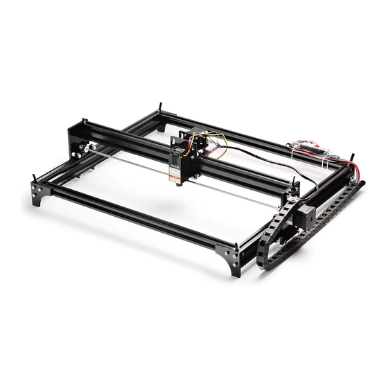
- Page 1 Genmitsu Laser Engraver LE5040 USER MANUAL...
-
Page 2: Part 1: Package List
Part 1: Package List Name Model Parameter Quantity Picture 480mm 2040 Aluminum Profile 580mm 2020 530mm Coupling 5-5mm M5x10 M5x20 M5x30 Bolt M5x45 M3x8 M3x25... - Page 3 Part 1: Package List Name Model Parameter Quantity Picture Acrylic Sheet A Acrylic Sheet B Acrylic Sheet C Acrylic Sheet D Acrylic Sheet E Acrylic Sheet F...
- Page 4 Part 1: Package List Name Model Parameter Quantity Picture Stepper Motor Hex Nut V Groove Bearing Laser Module Synchronous Wheel 2GT20 Bearing F685Z 5*11*4...
- Page 5 Part 1: Package List Name Model Parameter Quantity Picture Nylon Column 5x10 3x16 Self-tapping Screw M3x8 Copper Column M3x8 Gasket M5x7 T-Slot Nut 20TM5 Square Nut M3x10x5.5 Hex Wrench...
- Page 6 Part 1: Package List Name Model Parameter Quantity Picture Tank Drag Chain 10*10 30 knots Tank Drag Chain Bracket Linear Axis 590mm 540mm Timing Belt 630mm Control Board Stepper Motor Cable 4P USB Cable...
- Page 7 Part 1: Package List Name Model Parameter Quantity Picture Cable Wrap Cable Tie U disk Power Supply Goggle User Manual...
- Page 8 Part 2: Mechanical Installation 1. Base assembly...
- Page 9 Part 2: Mechanical Installation 2. Right bracket assembly * Install Y Axis stepper motor and coupling...
- Page 10 Part 2: Mechanical Installation * Install 4 V-Groove Bearings...
- Page 11 Part 2: Mechanical Installation 3. Left bracket assembly...
- Page 12 Part 2: Mechanical Installation 4. Laser module assembly * Fix the laser module on the Acrylic Sheet C with 4 Bolt M3*8...
- Page 13 Part 2: Mechanical Installation * The X-axis stepper motor was then attached to the Acrylic Sheet D using four Bolt M3*8. Fixing the Synchronous Wheel to the stepper motor through 2 set screws...
- Page 14 Part 2: Mechanical Installation * Assemble the two parts...
- Page 15 Part 2: Mechanical Installation 5. Pass the aluminum profile 2040*L580 through the installed laser module, then assemble the Linear Axis 5*L590, the left and right brackets.
- Page 16 Part 2: Mechanical Installation 6. Insert the assembled gantry bracket into the base...
- Page 17 Part 2: Mechanical Installation 7. Install 4 base brackets Acrylic Sheet E...
- Page 18 Part 2: Mechanical Installation...
- Page 19 Part 2: Mechanical Installation 8. Install control board * Fix the control board on Acrylic Sheet F...
- Page 20 Part 2: Mechanical Installation * Then fix the Acrylic Sheet F to the base bracket...
- Page 21 Part 2: Mechanical Installation 9. Install Timing Belt * Install Timing Belt L540 on both sides of the Y-axis...
- Page 22 Part 2: Mechanical Installation * Install the X-axis Timing Belt L630...
- Page 23 Part 2: Mechanical Installation 10. Install Tank Drag Chain * Pass the two stepper motor wires and the Tip: Bend the terminal 90 degrees and then laser head cable into the Tank Drag Chain wrap it in a carton sealing tape to make it easier to pass the Tank Drag Chain...
- Page 24 Part 2: Mechanical Installation * Fix Square Nut and Bolt * Then tighten the Tank Drag Chain Bracket * Fix the Tank Drag Chain on the M3*8 on the Tank Drag to the Aluminum Profile 2040 L480 nearthe Tank Drag Chain Bracket with Chain Bracket side of the control board.
-
Page 25: Part 3: Software Introduction
Part 3: Software Introduction 1. Control board wiring 12V Only Power SW Reset... - Page 26 Part 3: Software Introduction 2. Install the driver...
- Page 27 Part 3: Software Introduction 3. To Determine your Machine's COM port: * Windows XP: Right click on "My Computer", select "Manage", select "Device Manager". * Windows 7: Click "Start" Right click "Computer" Select "Manage" Select "Device Manager" from left pane. * In the tree, expand "Ports (COM &...
- Page 28 Part 3: Software Introduction 4. Open the software (LaserGRBL) 5. Connect the Control board to the PC via USB, Select the COM port recognized by the PC...
- Page 29 Part 3: Software Introduction 6. If the connection is successful, 7. Enter the command "M3 S50" in the console window print "Grbl 1.1f command window, then press Enter. ['$' for help]" The laser will be turned on with low If the port selection is wrong, no power model.
- Page 30 Part 3: Software Introduction 8. Rotate the lens to focus until the spot is focused to the minimum...
- Page 31 Part 3: Software Introduction 9. Then enter the command "M5" in the command window to turn off the laser. 10. File->Open File: Open GCODE file or Image format file...
- Page 32 Part 3: Software Introduction 11. Parameters default, click Next...
- Page 33 Part 3: Software Introduction 12. Set the Speed and S values. Note: Different materials need to set the engraving speed and S value are different, you need to try to find the appropriate value multiple times.
- Page 34 Part 3: Software Introduction 13. Set the zero point and click the button “Run Program ” to start engraving...
- Page 35 Part 3: Software Introduction 14. File->Save Program: Click to save GCODE file...
- Page 36 2711 Centerville Road, Wilmington, DE, 19808, United States...
Need help?
Do you have a question about the Genmitsu LE5040 and is the answer not in the manual?
Questions and answers