
Related Manuals for Mitsubishi Electric PUHY-P250YJM-A


Summary of Contents for Mitsubishi Electric PUHY-P250YJM-A
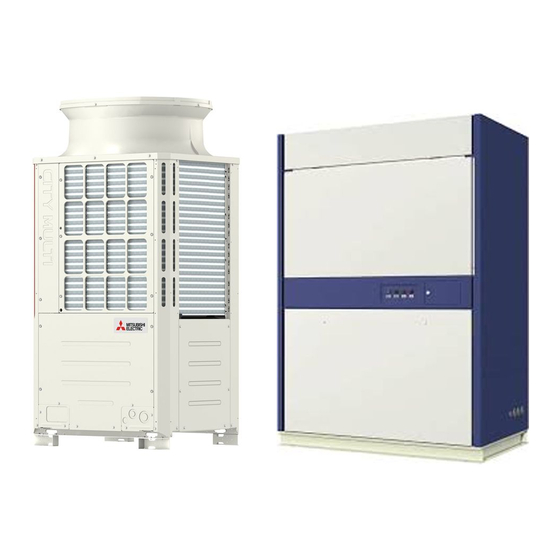
- Page 1 MODEL PUHY-P250YJM-A (-BS) PUHY-P500YSJM-A (-BS) PQHY-P250YHM-A PFD-P250VM-E PFD-P500VM-E DATA BOOK...
- Page 2 Safety Precautions ŒBefore installing the unit, thoroughly read the following safety precautions. ŒObserve these safety precautions for your safety. WARNING This symbol is intended to alert the user to the presence of important instructions that must be followed to avoid the risk of serious injury or death.
- Page 3 WARNING Securely attach the terminal block cover (panel) to the After completing the service work, check for a gas unit. leak. If the terminal block cover (panel) is not installed properly, If leaked refrigerant is exposed to a heat source, such as a dust and/or water may infiltrate and pose a risk of electric fan heater, stove, or electric grill, poisonous gases may be shock, smoke, and/or fire.
- Page 4 Precautions for handling units for use with R410A CAUTION Do not use the existing refrigerant piping. Use a vacuum pump with a reverse-flow check valve. ŒA large amount of chlorine that may be contained in the re- If a vacuum pump that is not equipped with a reverse-flow sidual refrigerant and refrigerating machine oil in the exist- check valve is used, the vacuum pump oil may flow into the ing piping may cause the refrigerating machine oil in the...
- Page 5 Before installing the unit WARNING Do not install the unit where a gas leak may occur. When installing the unit in a hospital, take appropriate measures to reduce noise interference. If gaseous refrigerant leaks and piles up around the unit, it may be ignited.
- Page 6 Before installing the unit (moving and reinstalling the unit) and performing electrical work CAUTION Properly ground the unit. Periodically check the installation base for damage. Do not connect the grounding wire to a gas pipe, water pipe, If the unit is left on a damaged platform, it may fall and lightning rod, or grounding wire from a telephone pole.
- Page 7 Before the test run CAUTION Turn on the unit at least 12 hours before the test run. Do not operate the unit without panels and safety guards. Keep the unit turned on throughout the season. If the unit is turned off in the middle of a season, it may result in malfunc- Rotating, high-temperature, or high-voltage parts on the unit tions.
-
Page 8: Table Of Contents
CONTENTS Safety Precautions General Equipment Descriptions 1. Unit configuration table..........................1 2. Operable temperature range .......................... 3 Product Specifications 1. Specifications ..............................4 (1) Indoor unit (2) Outdoor unit/Heat source unit 2. External Dimensions ............................6 (1) Indoor unit (2) Outdoor unit/Heat source unit 3. - Page 9 CONTENTS 7. External input/output specifications ......................51 (1) Input/output specifications (2) Wiring (3) Wiring Method (4) Switch setting (5) Dehumidification priority control (6) Normal/Local switching switch (SW9) 8. System Rotation Control ..........................56 9. Notes on the use of optional accessories ....................56 10.
-
Page 10: I General Equipment Descriptions
M-NET PAC-SC51KUA When using a PFD-P250VM-E as an indoor unit, connect an outdoor unit PUHY-P250YJM-A/PQHY-P250YHM-A to each indoor unit and operate with a built-in remote controller for the indoor unit. *1: Bold line indicates refrigerant piping (gas/liquid). This system consists of single refrigerant circuit. - Page 11 PAC-SC51KUA Refrigerant pipe When using a PFD-P500VM-E as an indoor unit, connect 2 PUHY-P250YJM-A/PQHY-P250YHM-A outdoor units to an indoor unit and operate with a built-in remote controller for the indoor unit. At the factory settings, this model of indoor unit is designed and set to accommodate a single refrigerant circuit.
-
Page 12: Operable Temperature Range
2. Operable temperature range PFD unit + PUHY-P250YJM-A, PUHY-P500YSJM-A • Cooling Outdoor temperature (°CDB) * The height between the Outdoor PUHY-P-YJM-A and Indoor could make the operation temperature range narrow. For details, refer to IV 1. Piping Design (P27). • Heating Outdoor temperature (°CWB) -
Page 13: Product Specifications
Connection of two refrigerant circuits to the indoor unit requires setting change and pipe work. Installation/foundation work, electric connection work, duct work, insulation work, power source switch and other items are not specified in the specifications. (2) Outdoor unit/Heat source unit Model name PUHY-P250YJM-A (-BS) connected with PFD series Cooling Heating Capacity 28.0... - Page 14 Capacity 56.0 63.0 Power source 3N ~ 380/400/415V 50/60Hz Power input 13.60 13.20 Current 22.8/21.8/21.0 22.2/21.0/20.4 Set Model PUHY-P250YJM-A(-BS) PUHY-P250YJM-A(-BS) Type Quantity Propeller fan x 1 Propeller fan x 1 Airflow rate /min Motor output 0.46 0.46 Type Inverter scroll hermetic compressor...
-
Page 15: External Dimensions
2. External Dimensions (1) Indoor unit PFD-P250VM-E Unit : mm - 6 -... - Page 16 PFD-P500VM-E Unit : mm - 7 -...
- Page 17 (2) Outdoor unit/Heat source unit PUHY-P250YJM-A(-BS) Unit : mm - 8 -...
- Page 18 PUHY-P500YSJM-A(-BS) Unit : mm - 9 -...
- Page 19 PQHY-P250YHM-A Unit : mm - 10 -...
-
Page 20: Center Of Gravity
3. Center of Gravity (1) Indoor unit PFD-P250VM-E Unit : mm Model PFD-P250VM-E PFD-P500VM-E Unit : mm Model PFD-P500VM-E - 11 -... - Page 21 (2) Outdoor unit/Heat source unit PUHY-P250YJM-A (-BS) Unit : mm Model PUHY-P250YJM-A (-BS) PQHY-P250YHM-A Unit : mm Model PQHY-P250YHM-A - 12 -...
-
Page 22: Electrical Wiring Diagrams
4. Electrical Wiring Diagrams (1) Indoor unit PFD-P250VM-E - 13 -... - Page 23 PFD-P500VM-E - 14 -...
- Page 24 (2) Outdoor unit/Heat source unit PUHY-P250YJM-A (-BS) - 15 -...
- Page 25 PQHY-P250YHM-A - 16 -...
-
Page 26: Optional Parts
5. Optional Parts (1) Outdoor unit Outdoor twinning kit The following optional Outdoor Twinning Kit is needed to use to combine multiple refrigerant pipes. Refer to the chapter entitled System Design Section for the details of selecting a proper twinning kit. CMY-Y100VBK2 For Liquid pipe: For Gas pipe:... -
Page 27: Product Data
III Product Data (PEFY-AF1200CFMR) Product Data 1. Capacity Curves (1) Correction by temperature PUHY-P250YJM-A, PUHY-P500YSJM-A Cooling Capacity Cooling Input Indoor unit inlet temperature (°CWB) Indoor unit inlet temperature (°CWB) -15 -10 -15 -10 Outdoor unit inlet temperature (°CDB) Outdoor unit inlet temperature (°CDB) The correction curves indicate the values measured at the point where the compressor was operated at its maximum capacity. - Page 28 6.01 5.47 5.00 4.60 4.43 * Indoor air temperature condition: 27°CDB/19°CWB 20HP System Indoor Unit : PFD-P500VM-E Outdoor Unit : PUHY-P250YJM-A × 2, PUHY-P500YSJM-A System Power input (kW) Outdoor unit inlet Cooling 100% temp. (°CDB) Capacity (kW) Capacity Capacity Capacity...
- Page 29 To obtain a decrease in cooling/heating capacity due to refrigerant piping extension, multiply by the capacity correction factor based on the refrigerant piping equivalent length in the table below. PUHY-P250YJM-A, PUHY-P500YSJM-A, PQHY-P250YHM-A Piping equivalent length (m) • How to obtain piping equivalent length 1.
- Page 30 (5) SHF Curves Standard Capacity Ratio Standard Capacity Ratio 130% 120%110% 100% 90% 130% 120%110% 100% 90% Indoor Temperature 27°CDB Indoor Temperature 24°CDB 0.93 RH (%) RH (%) Standard Capacity Ratio Standard Capacity Ratio 120% 110% 100% 90% 120% 110% 100% 90% Indoor Temperature 22°CDB Indoor Temperature 20°CDB RH (%)
-
Page 31: Sound Levels
▪ Measured in anechoic room. ▪ Measured without effect of discharge air. ▪ External pressure is 120Pa. Outdoor unit Sound pressure level Measurement Series (dB [Type A]) location PUHY-P250YJM-A Measurement Sound pressure level Series location (dB [Type A]) PUHY-P500YSJM-A Heat source unit Measurement... - Page 32 NC-20 NC-20 continuous noise continuous noise Octave band central frequency (Hz) Octave band central frequency (Hz) PUHY-P250YJM-A (External static pressure 0Pa) PUHY-P500YSJM-A (External static pressure 0Pa) dB(A) dB(A) Standard 50/60Hz 60.0 63.0 61.0 55.0 52.0 47.5 42.5 36.5 58.0...
-
Page 33: Fan Characteristics Curves
Ø170-B-2-28 Ø315-B-2-42 Ø160-B-2-28 Ø355-B-2-42 Ø160-B-2-28 Ø315-B-2-42 Note1 Pulley and V-belt is procured on site. Note2 Mitsubishi Electric shall not be held responsible for the pulley modified on site. PFD-P500VM-E : 50/60Hz, Standard 1200rpm Output 5.5kW 1100rpm Fan rotation speed 1000rpm... - Page 34 Shape of the pulley (unit : mm) 12.5 12.5 (keyway) Rz 6.3 Rz 6.3 Rz 6.3 Rz 3.2 : Pulley nominal diameter 34° Belt 161 < d 36° 201 < d 38° Motor pulley Fan pulley Nominal Outside Nominal Outside Bore (B) Bore (B) Diameter (A)
- Page 35 ŒHorizontal pulley alignment and proper belt tension 1) The fan pulley and the motor pulley must be aligned to meet the criteria shown in Fig. 3-1 and Table 1. 2) Set the tension for the V-belt so that the deflection force falls within the range as shown in Table 2. 3) After the belt has been broken in on the pulley (after 24 to 28 hours of operation), check the belt for looseness and adjust the belt tension as specified in step 2) above as necessary.
-
Page 36: System Design
IV Piping Design (PEFY-AF1200CFMR) System Design 1. Piping Design (1) PFD-P250VM-E Fig.IV-1-(1)A: PUHY Piping Design Fig.IV-1-(1)B: PQHY Piping Design IU: Indoor unit, OU: Outdoor unit, HU: Heat source unit Table: I V-1 -(1 ) - 1 . Piping length Item Piping in the figure Max. - Page 37 (2) PFD-P500VM-E (two refrigerant circuit system) Fig.IV-1-(2)A: PUHY Piping Design Fig.IV-1-(2)B: PQHY Piping Design IU: Indoor unit, OU: Outdoor unit, HU: Heat source unit Table: IV-1 -(2 )- 1 . Piping length Item Piping in the figure Max. length Max. equivalent length Farthest IU from OU/HU (L) Height between OU/HU and IU (OU/HU above IU) Height between OU/HU and IU (OU/HU under IU)
- Page 38 (3) PFD-P500VM-E (single refrigerant circuit system) Note1. If the A/C system is designed to use cooling mode under outdoor temperature 10°C, H’<=15m. Note2. As bents cause pressure loss on transportation of refrigerant, fewer bents design is better; Piping length needs to consider the actual length and equivalent length which bents are counted. Equivalent piping length (m)=Actual piping length+"M"...
- Page 39 Sample calculation Amount of factory- charged refrigerant A : ø9.52 B : ø9.52 Model Charged amount C : ø15.88 PUHY-P250YJM-A 8.0kg PQHY-P250YHM-A 5.0kg Total length for ø15.88 C=2m each pipe size : ø9.52 A+B=5m This yields the following result: =2x0.2+5x0.06+4.0...
-
Page 40: Designing Of Water Circuit System
2. Designing of water circuit system (1) Example of basic water circuit The water circuit of the water heat source CITY MULTI connects the heat source unit with the cooling tower/auxiliary heat source/heat storage tank/circulation pump with a single system water piping as shown in the figure below. The selector valve automatically controls to circulate water toward the cooling tower in the cooling season, while toward the heat storage tank in the heating season. - Page 41 (2) Cooling tower a) Types of cooling tower The cooling towers presently used include the open type cooling tower, open type cooling tower + heat exchanger, closed type cooling tower, and air-cooled type cooling tower. Types of cooling towers However, as the quality control of circulation water is essential when units are installed in decentralized state inside a building, the closed type cooling tower is generally employed in such case.
- Page 42 (3) Auxiliary heat source and heat storage tank When the heating load is larger than the cooling load, the circulation water temperature lowers in accordance with the heat balance of the system. It should be heated by the auxiliary heat source in order to keep the inlet water temperature within the operating range (10°C[50°F] or more) of the water heat source CITY MULTI.
- Page 43 When heat storage tank is not used • - 860 x Pw x T QH = (kcal) (kcal/day) Total of heating load on weekday including warming up Operating hour of auxiliary heat source Operating hour of heat source water pump 1.05~1.10 Allowance factor (Heat storage tank, piping loss, etc.) is calculated from the result of steady state load calculation similarly by using the equation below.
- Page 44 b) Heat storage tank Heat storage tank can be classified by types into the open type heat storage tank exposed to atmosphere, and the closed type heat storage tank with structure separated from atmosphere. Although the size of the tank and its installation place should be taken into account, the closed type tank is being usually employed by considering corrosion problems.
- Page 45 (4) Piping system The following items should be kept in your mind in planning / designing water circuits. a) All units should be constituted in a single circuit in principle. b) When plural numbers of the water heat source CITY MULTI unit are installed, the rated circulating water flow rate should be kept by making the piping resistance to each unit almost same value.
- Page 46 (5) Practical System Examples and Circulation Water Control Since the water heat source CITY MULTI is of water heat source system, versatile systems can be constituted by combining it with various heat sources. The practical system examples are given below. Either cooling or heating operation can be performed if the circulation water temperature of the water heat source CITY MULTI stays within a range of 10~45°C [50~113°F].
- Page 47 Example-2 Combination of closed type cooling tower and hot water heat storage tank T1 : Proportional type, insertion system thermostat T2 : Proportional type, insertion system thermostat T3 : Proportional type, insertion system thermostat V1 : Proportional type, motor-driven 3-way valve V2 : Proportional type, motor-driven 3-way valve XS : Auxiliary switch (Duplex switch type) SC : Step controller...
- Page 48 Example-3 Combination of closed type cooling tower and boiler T1 : Proportional type, insertion system thermostat T2 : Proportional type, insertion system thermostat T3 : Proportional type, insertion system thermostat V1 : Proportional type, motor-driven 3-way valve : Selector switch : Relay XS : Auxiliary switch (Duplex switch type) Closed type...
- Page 49 Example-4 Combination of closed type cooling tower and heat exchanger (of other heat source) T1 : Proportional type, insertion system thermostat T2 : Proportional type, insertion system thermostat V1 : Proportional type, motor-driven 3-way valve V2 : Proportional type, motor-driven 3-way valve : Selector switch : Relay XS : Auxiliary switch (Duplex switch type)
- Page 50 (6) Pump interlock circuit Operating the heat source unit without circulation water inside the water piping can cause a trouble. Be sure to provide interlocking for the unit operation and water circuit. Since the terminal block is being provided inside the unit, use it as required. Wiring diagram This circuit uses the “Terminal block for pump interlock (TB8)”...
-
Page 51: Water Piping Work
3. Water piping work Although the water piping for the CITY MULTI WY system does not differ from that for ordinary air conditioning systems, pay special attention to the items below in conducting the piping work. (1) Items to be observed on installation work ŒIn order to equalize piping resistance for each unit, adapt the reverse return system. -
Page 52: Control Wiring
4. Control Wiring Restrictions when the PFD-type indoor units are connected (related to the system) ŒThe PFD-type indoor units cannot be connected to the ME remote controller. ŒThe address settings must be made on this system. ŒThe following functions cannot be selected on the PFD-type indoor units. a) Switching between automatic power recovery Enabled/Disabled (Fixed to "Enabled"... -
Page 53: Types Of Switch Settings And Setting Methods
5. Types of switch settings and setting methods Whether a particular system requires switch settings depends on its components. Refer to the section “6. Sample System Connection” before conducting electrical work. Keep the power turned off while setting the switches. If settings are changed while being powered, the changed settings will not register, and the unit may malfunction. - Page 54 (2) Power supply switch connector connection on the outdoor unit (Factory setting: The male power supply switch connector is connected to CN41.) Grouping the indoor Connection to Power supply unit System units connected to the system for transmission Power supply switch connector connection configuration different outdoor controller...
-
Page 55: Sample System Connection
6. Sample System Connection (1) System with MA remote controller 1) Single refrigerant circuit Control Wiring Diagram Leave the male Leave the male connector on connector on CN41 as it is. * One indoor controller (controller circuit board) CN41 as it is. is equipped in the indoor unit (10HP), and two indoor controllers (controller circuit boards) are equipped in the indoor unit (20HP). - Page 56 2) Two refrigerant circuits Control Wiring Diagram Disconnect the male power supply connector from CN40 and connect it to CN41. TB5-1 M1M2 S M1 M2 A1 B1 S TB15 Connection Leave the male connector on CN41 as it is. TB5-2 M1 M2 A2B2 S M1 M2 S...
- Page 57 3) System in which two MA remote controllers are connected to one indoor unit Control Wiring Diagram Leave the male Leave the male connector on connector on CN41 as it is. CN41 as it is. * One indoor controller (controller circuit board) is equipped in the indoor unit (10HP), and two indoor controllers (controller circuit boards) TB5-1...
- Page 58 4) System in which two indoor units are grouped with the MA remote controller Control Wiring Diagram Leave the male Leave the male connector on connector on Leave the male connector on Leave the male connector on CN41 as it is. CN41 as it is.
- Page 59 (2) System with MA remote controller and AG-150A 1) System with multiple indoor units (10HP, 20HP) Control Wiring Diagram * There is one indoor controller * There are two indoor controller board inside indoor unit. boards inside indoor unit. Use CN41 as is. Use CN41 as is.
-
Page 60: External Input/Output Specifications
7. External input/output specifications (1) Input/output specifications Input Function Usage Signals · Pulse [Factory setting: Dip SW1-9 ON] (a-contact with voltage/without voltage) *1 <With voltage> Power Source: DC12~24V Electrical Current: Approximately 10mA (DC12V) Turning ON/OFF <Standard Pulse> Start/stop the indoor unit over 200ms over 200ms... - Page 61 (2) Wiring External input/output board Input with voltage TB23 External power source SW12 Stop/Start (*1) Short circuit plate Input without voltage TB21 CN53 Common SW11 Stop/Start (*1) Short circuit plate Relay Contact Point Output TB22 Power Source for Display No.1 Operation Status CN54 No.1 Error Status * No.2 Operation Status...
- Page 62 Caution on using the external input function (20HP only) CAUTION When using the external input function on the indoor unit that is connected to a two-refrigerant circuit, connect the short-circuit plate that is supplied with the unit to the appropriate terminals on the external input-output board. Without the short-circuit plate, the unit will not function properly.
- Page 63 (3) Wiring Method 1) Check the indoor unit setting (Refer to 7-(2) Wiring ) 2) When using the external output function, connect each signal line to External output Terminal (TB22) on the unit, depending on the usage. 3) When using external input function, peal the outer layer of the signal line off, and connect it to external input terminal (TB21 or TB23) on the unit, depending on the usage.
- Page 64 (4) Switch setting The suction/discharge air temperature control of the indoor unit. Either suction temperature control or discharge temperature control can be selected. The suction/discharge temperature control can be switched by the switches (SWC) on the controller circuit board inside the controller of the indoor unit.
-
Page 65: System Rotation Control
9. Notes on the use of optional accessories WARNING Only use optional parts recommended by Mitsubishi Electric. These parts should only be installed by a qualified technician. Improper installation may result in water leakage, electric shock, or fire. - 56 -... -
Page 66: Caution For Refrigerant Leakage
Note 1. Countermeasure 3 should be done in a proper way in which the fresh air supply shall be on whenever the leakage happens. Note 2. In principle, MITSUBISHI ELECTRIC requires proper piping design, installation and air-tight testing after installation to avoid leakage happening.In the area should earthquake happen, anti-vibration measures should be fully considered.The piping should consider the... -
Page 67: Air Conditioning The Computer Room
V Wiring Design (PEFY-AF1200CFMR) Air Conditioning the Computer Room 1. Main Features of the Floor-Duct Air Conditioners This system is installed by building a floor over an existing floor and using the space between these two floors as an air-conditioning duct. This system has the following characteristics: ŒThe temperature and humidity can efficiently and reliably be controlled, since the air-conditioned air is sent directly to the machine. -
Page 68: Step-By-Step Plan For The Implementation Of The Air-Conditioning
3. Step-by-Step Plan for the Implementation of the Air-Conditioning Purpose Making decisions on the computer system Basic Accommodates possible future expansion (ensuring the acquisition route) Conditions Operation schedule Back-up system (in case of breakdowns, power outage, water-supply cut offs etc.) Air conditioning methods (continuous, floor-duct type etc.) Securing Computer room, CVCF room, MT Disk Storage room... -
Page 69: Conditions For The Installation Of Computer-Room Air Conditioners
4. Conditions for the Installation of Computer-Room Air Conditioners (1) Outdoor Temperature and Humidity Usually, outdoor temperature/humidity conditions that are adopted for general air conditioning are used. However, for the spaces that require stringent temperature/humidity control, such as computer rooms, higher values may be adopted. (2) Indoor Temperature and Humidity There is a wide range of conditions set by different computer manufacturers, and the conditions need to be set in consultation with the manufacturers. -
Page 70: Setting The Air Conditioners
5. Setting the Air conditioners (1) Air-Conditioning Load 1) Once the floor plan is made and the conditions for the air-conditioning system are set, air conditioning capacity has to be determined by calculating the heat load. 2) Unlike the outdoor air, computer heat load remains constant throughout the year. However, it is possible that there are considerable fluctuations within a day. - Page 71 Indoor °CDB 24°C/Indoor °CWB 17°C outdoor °CDB 32°C Capacity of the Moment 54.3kW SHF = 0.92 Capacity of Sensible Heat 54.3 × 0.92 = 49.9/kW Standard Air-Flow Volume: 320m /min can be accommodated with PUHY-P250YJM-A × 2 and PFD-P500VM-E. - 62 -...
-
Page 72: Automatic Control Of The Computer Room
6. Automatic Control of the Computer Room Example PFD-P500VM-E automatically controls the cooling temperature with a built-in controller. (suction air temperature or discharge air temperature control) This unit is designed for high sensible-heat specifications, and it does not include a humidifier or a dehumidifier. Install such components as necessary. -
Page 73: Maintenance/Inspection
VI General Equipment Descriptions (PEFY-AF1200CFM) Maintenance/Inspection 1. Maintenance/Inspection Schedule Having the units inspected by a specialist on a regular basis, in addition to regular maintenance such as changing the filters, will allow the users to use them safely and in good condition for an extended period of time. The chart below indicates standard maintenance schedule. - Page 74 (3) Details of Maintenance/Inspection Inspection Unit Parts Check points Assessment What to do Cycle . Free of unusual noise Fan motor . Check for unusual noise Replace when insulation . Insulation resistance over 1M . Measure the insulation resistance is under 1M resistance .
- Page 76 - It may also be in violation of applicable laws. - MITSUBISHI ELECTRIC CORPORATION cannot be held responsible for malfunctions or accidents resulting from the use of the wrong type of refrigerant. HEAD OFFICE: TOKYO BLDG., 2-7-3, MARUNOUCHI, CHIYODA-KU, TOKYO 100-8310, JAPAN http://Global.MitsubishiElectric.com...
- Page 77 Related Links Model Number: PFD-P250VM-E KS6-250-500 PFD Stands Installation Manual (Issue 1) PFD-P250-500VM-E Databook (MEE13K035) PFD-P250-500VM-E Declaration of Conformity PFD-P250-500VM-E Installation Manual (WT04836X05) PFD-P250-500VM-E Instruction Book (WT07347X02) PFD-P250-500VM-E Parts Catalogue (BWE0609D) PFD-P250-500VM-E Service Manual (HWE1018A) PFD-P250-500VM-E_Declaration_of_Conformity_(EU06001A) PFD-P250-500VM_Installation_Manual_(WT04836X02) PFD-P250-500VM_Instruction_Book_(WT04835X01) PFD-P250-500VM_Parts_Catalog_(BWE0609B) PFD-P250-500VM_Service_Manual_(HWE05250) PFD-P250-500VM_Service_Manual_(HWE07190)