Nortel DMS-100 Series Maintenance Manual
Remote line concentrating module
Hide thumbs
Also See for DMS-100 Series:
- Replacement procedures (1100 pages) ,
- Maintenance manual (762 pages) ,
- Manual (543 pages)
Table of Contents
Advertisement
Quick Links
Critical Release Notice
Publication number: 297-8351-550
Publication release: Standard 04.02
The content of this customer NTP supports the
SN06 (DMS) and ISN06 (TDM) software releases.
Bookmarks used in this NTP highlight the changes between the baseline NTP and the current
release. The bookmarks provided are color-coded to identify release-specific content changes. NTP
volumes that do not contain bookmarks indicate that the baseline NTP remains unchanged and is
valid for the current release.
Bookmark Color Legend
Black: Applies to new or modified content for the baseline NTP that is valid through the
current release.
Red: Applies to new or modified content for NA017/ISN04 (TDM) that is valid through the
current release.
Blue: Applies to new or modified content for NA018 (SN05 DMS)/ISN05 (TDM) that is valid
through the current release.
Green: Applies to new or modified content for SN06 (DMS)/ISN06 (TDM) that is valid
through the current release.
Attention!
Adobe
Acrobat
Reader
5.0 is required to view bookmarks in color.
Advertisement
Table of Contents
Troubleshooting

Related Manuals for Nortel DMS-100 Series


Summary of Contents for Nortel DMS-100 Series
- Page 1 Critical Release Notice Publication number: 297-8351-550 Publication release: Standard 04.02 The content of this customer NTP supports the SN06 (DMS) and ISN06 (TDM) software releases. Bookmarks used in this NTP highlight the changes between the baseline NTP and the current release.
- Page 2 Publication History March 2004 Standard release 04.02 for software release SN06 (DMS) and ISN06 (TDM). Change of phone number from 1-800-684-2273 to 1-877-662-5669, Option 4 + 1.
- Page 3 297–8351–550 DMS-100 Family Remote Line Concentrating Module Maintenance Manual XPM12 and up Standard 04.01 August 1999...
- Page 5 Nortel Networks, the holder is granted no rights to use the information contained herein. Information is subject to change without notice. Nortel Networks reserves the right to make changes in design or components as progress in engineering and manufacturing may warrant.
-
Page 7: Table Of Contents
Contents About this document When to use this document ix How to check the version and issue of this document ix References in this document x What precautionary messages mean x How commands, parameters, and responses are represented xi Input prompt (>) xi Commands and fixed parameters xi Variables xi Responses xii... - Page 8 iv Contents RMM maintenance 1-64 Drawer testing 1-64 BIC relay test (BRT) 1-67 Subscriber lines automatic maintenance 1-75 LCM REXTEST 1-75 System REX controller: XPM maintenance 1-77 Increase to manual maintenance 1-84 Alarm conditions 1-84 Subscriber lines manual maintenance 1-86 Drawer maintenance 1-86 PRLCM overview PRLCM configuration 2-1...
- Page 9 Contents v Routine exercise test 3-29 ESA ROM diagnostics 3-30 ESA RAM diagnostics 3-31 Escalation to manual maintenance 3-31 Loading ESA static translations data 3-31 ESA manual exit 3-32 LTC maintenance to prevent ESA mode 3-32 Signaling for RLCM Signaling for RLCM 4-1 RLCM signaling links 4-1 Signaling protocol 4-2 Signaling functions 4-4...
- Page 10 vi Contents NT2X11 RMM 8-40 NT2X48 RMM 8-44 NT2X57 RMM 8-49 NT2X59 RMM 8-53 NT2X70 HIE 8-59 NT2X90 RMM 8-75 NT3X09 RMM 8-81 NT6X17 RLCM 8-86 NT6X18 RLCM 8-90 NT6X19 RLCM 8-95 NT6X20 RLCM 8-99 NT6X21 RLCM 8-103 NT6X27 in HIE 8-108 NT6X36 RLCE 8-116 NT6X45 HIE 8-121 NT6X47 HIE 8-128...
- Page 11 Contents vii Automatic line tests 10-8 Station tests 10-10 Manual line tests 10-11 Ring pretrip on LCM lines 10-11 Product-specific test tools 10-14 Line maintenance cutover (LMCUT) 10-14 Troubleshooting chart 11-1 Advanced troubleshooting procedures 12-1 Powering up the RLCM 12-1 Powering down the RLCM 12-2 Common procedures 12-3 Troubleshooting a failure to load 12-3...
-
Page 13: About This Document
About this document When to use this document This Remote Line Concentrating Module with Extended Distance Capability (RLCM-EDC) maintenance reference manual provides: overview, signal- ing, and hardware information for understanding the RLCM-EDC product and operation; recovery procedure for returning to service an RLCM-EDC from a completely out-of-service condition;... -
Page 14: References In This Document
x About this document organized, check the release information in Product Documentation Directory, 297-8991-001. References in this document The following documents are referred to in this document: Operational Measurements Reference Manual Input/Output System Reference Manual, 297-1001-129 Extended Peripheral Module Translations Reference Manual Provisioning Guide, PLN-8991-104 1-Meg Modem Network Implementation Manual, 297-8063-200 What precautionary messages mean... -
Page 15: How Commands, Parameters, And Responses Are Represented
About this document xi WARNING Possibility of equipment damage WARNING Damage to the backplane connector pins Align the card before seating it, to avoid bending the backplane connector pins. Use light thumb pressure to align the card with the connectors. Next, use the levers on the card to seat the card into the connectors. -
Page 16: Responses
xii About this document Responses Responses correspond to the MAP display and are shown in a different type: FP 3 Busy CTRL 0: Command request has been submitted. FP 3 Busy CTRL 0: Command passed. The following excerpt from a procedure shows the command syntax used in this document: Manually busy the CTRL on the inactive plane by typing >BSY CTRL ctrl_no... -
Page 17: Maintenance Overview
Maintenance overview The Remote Line Concentrating Module (RLCM) is a remote peripheral that provides extended geographic coverage for the Digital Multiplex System-100 (DMS-100) switch. The RLCM operates at a maximum of 160.9 km (100 mi) from the host office. The RLCM contains hardware and software maintenance components that perform routine audits and identify failures in the following: RLCM DS-1 links that connect the RLCM to the host controller... -
Page 18: General Configuration
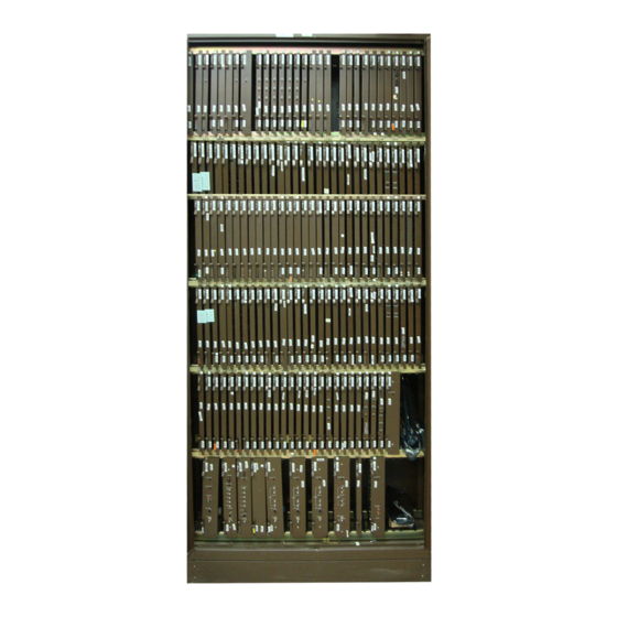
1-2 Maintenance overview General configuration A standard DMS-100 switch single-bay equipment frame houses the RLCM. The RLCM frame contains the following main components: standard two-shelf line concentrating module (LCM) single-shelf remote maintenance module (RMM) host interface equipment (HIE) shelf frame supervisory panel (FSP) The lower part of the frame contains the LCM. - Page 19 Maintenance overview 1-3 RLCM frame, shelf, and panel arrangement Shelf position Frame supervisory panel Office repeaters Remote maintenance module 2 Link control Cooling baffle cards 2 to 3 DS-1 interface cards 2 Ringing Host interface equipment generators 2 Power converters 5 Line Cooling baffle and fuse panel drawers...
-
Page 20: Lca Shelf Configuration
1-4 Maintenance overview In the RLCM, the LCM connects from two to six DS-1 C-side links to the 640 subscriber lines of the LCM. This interface consists of the following LCM components: 2 power converters 2 control complexes (LCM processor and digroup control card) 20 LSGs The RLCM has a minimum of two DS-1 links because each primary link carries one message channel to the LGC or LTC. -
Page 21: Lcm Control Complex Cards
Maintenance overview 1-5 Line concentrating array (LCA) shelf layout LCA: NT6X04AA, AB Power converter Even Even Even Even Even Slot: 01 02 04 05 Line drawers Slot Abbr NT PEC Remarks 01–03 6X53AA Power converter. Also contains ringing and ANI voltage switching circuits. LCMP 6X51AA, AB LCM processor card (see note) - Page 22 1-6 Maintenance overview The XLCM contains 256 kB of RAM storage. The XLCM collects dial pulse digits from subscriber lines and handles messages to and from the host LTC or LGC. This action occurs for a maximum of 640 lines. The NT6X51AB/AC requires XLCM software loads.
-
Page 23: Line Drawers
Maintenance overview 1-7 Line drawers Each line drawer (NT6X05) in the LCA shelf has one bus interface card (BIC) and a maximum of 64 line cards of different types. The side view of a normal LCA line drawer appears in the following figure. You can remove the line drawer from the frame to access line circuit cards. - Page 24 1-8 Maintenance overview Drawer state display The status of the drawers appears below the status of the LCM units. The drawers are numbered from 0 through 19 and grouped in pairs. The drawers are grouped in pairs to show that the groups share the same BIC card and normally interface a different processor.
- Page 25 Maintenance overview 1-9 Performs digital looparound on command from the maintenance system. Communication between LCA-0 and LCA-1, or between two LSGs occurs through the single BIC in each drawer. Line cards The line cards are behind the BIC in 4 rows of a maximum of 16 line cards. The top two rows of line cards form the odd-numbered LSG.
- Page 26 1-10 Maintenance overview A complete LEN for an RLCM line card consists of five units of information. Example LENs appear in the following table. This example illustrates LENs for line cards in a normal office. The first two LENs are for RLCM-supported lines.
- Page 27 Maintenance overview 1-11 Message-waiting line circuit (NT6X19AA). Provides the features of the type A line circuit, plus a message-waiting lamp driver circuit. When activated, this circuit causes the message waiting lamp on the associated telephone set to flash at 1 Hz. This action informs the subscriber that the subscriber has a message.
- Page 28 1-12 Maintenance overview Recommended NT6X21AD S1 DIP switch settings Recommended D/A voice Balance Signaling level application S3 and S4 Switch position Switch position Both Only Only Both S4 ON S3 ON –3.5dB 1.3Vpp 0.8Vpp 0.6Vpp 0.14Vpp P-phone sets long loop: 19–24dB EML P-phone sets medium loop:...
- Page 29 Maintenance overview 1-13 The two acceptable limits for transhybrid loss (THL) that depend on the selected D/A level appear in the following two tables. The NT6X21AD uses the same diagnostics as the NT6X21AC. The THL limits are modified for diagnostics purposes. The first table is for the NT6X21AC line card, the next table is for the NT6X21AD line card.
- Page 30 1-14 Maintenance overview LCA block diagram Control complex Line drawers Ports 6X52 Drawer 9 1–3 DS30A 0,1,2 LCC -1 Drawer 5 Line 6X51 LSG 11 Digroup 6X54 Card 0 Control Processor Card Card Line Card LSG 10 3,4,5 Card 0 6X53 Power Converter...
-
Page 31: Hie Description
Maintenance overview 1-15 HIE description The HIE occupies a single shelf at position 38 in the RLCM frame. The HIE allows the LCA shelves of the RLCM to connect to the RMM and to the host office. The HIE shelf contains the following components: two ringing generators two LCCs two to three DS-1 interface cards... - Page 32 1-16 Maintenance overview HIE shelf layout HIE: NT6X11AA Power Power RG-0 RG-1 Fillers converter converter 01 02 03 04 05 06 07 08 09 10 11 12 13 14 15 16 17 18 19 20 21 22 23 24 25 NT PEC Remarks Abbr...
- Page 33 Maintenance overview 1-17 Under normal conditions, when both LCCs are active, LCC-0 connects LCA-0, and LCC-1 connects LCA-1. The LCC-0 serves even numbered DS-1 links (0, 2, and 4) from the DS-1 interface cards. The LCC-1 serves odd numbered DS-1 links (1, 3, and 5). The following figure describes how the LCCs are configured in the RLCM.
- Page 34 1-18 Maintenance overview The LCC also provides system clocks for the DCC, RMM, and LCM. When each unit of the LCM is active, LCC-0 is frequency-locked to the associated primary DS-1 link. The LCC-1 clock is locked to LCC-0. The two LCC clocks derive timing from the host LTC.
-
Page 35: Intracalling Channel Availability
Maintenance overview 1-19 A minimum of two DS-1 cards are required. Different cards must carry the two primary message channels from the LCM for reliability. A third DS-1 card is added if the system requires six DS-1 links to the host to handle the traffic load of the RLCM. - Page 36 1-20 Maintenance overview RLCM channel and connection availability Host Host channels Interchannels Total Total DS-1 intra- active links calls calls Note 1: Host channels column A: The total host speech channels available. Note 2: Host channels column B: The total host speech channels minus two channel supervision messaging channels.
- Page 37 Maintenance overview 1-21 Six-host-links configuration The figure below shows the channel availability for an RLCM with six DS-1 host links balanced evenly between LCC 0 and LCC 1. Each primary port of an LCM provides an interface between 30 DS30A channels making 120 channels available for each LCM.
- Page 38 1-22 Maintenance overview Five-host-links configuration With five host links, the number of intraswitching channels for LCC 0 increases by 24. The 24 channels are from the unequipped DS-1 port, which causes unbalanced traffic capacities in the RLCM. Because the number of channels for each LCC is unbalanced, blocking may occur if subscribers are evenly distributed on the LCM units.
- Page 39 Maintenance overview 1-23 Channel availability with four host DS-1 links DS30A links from DS30A links from LCM 0 controller ports LCM 0 controller ports 0 1 2 3 4 5 6 7 LCC 0 LCC 1 transmitter transmitter Host links Host links Interchannels 2 X 24 = 48...
- Page 40 1-24 Maintenance overview Channel availability with three host DS-1 links DS30A links from DS30A links from LCM 0 controller ports LCM 0 controller ports 0 1 2 3 4 5 6 7 LCC 0 LCC 1 transmitter transmitter Host links Host links Interchannels 2 X 24 = 48...
-
Page 41: Esa Channel Availability
Maintenance overview 1-25 Channel availability with two host DS-1 links DS30A links from DS30A links from LCM 0 controller ports LCM 0 controller ports 0 1 2 3 4 5 6 7 LCC 0 LCC 1 transmitter transmitter Host links Host links Interchannels 1 X 24 = 24... - Page 42 1-26 Maintenance overview Maximum number of calls during ESA Total number of possible ESA Number of Intercalls Intracalls calls host links Power converter card The two HIE power converters, in slots 22 and 25, supply the necessary shelf voltages (5 V, 12 V) for the HIE shelf. ESA control complex If the user selects the ESA feature package, two configurations are possible.
- Page 43 Maintenance overview 1-27 RLCM link, port and channel structure ports DS-1 channels link Equipped DS-1 channels Primary link Equipped ports DS-1 channels link Equipped To mate Image links 1, DS30A ports 320 lines 3, and 5 Interunit link Interunit port RMM link RMM port unit 0...
-
Page 44: 1-Meg Modem Service
1-28 Maintenance overview 1-Meg Modem Service The RLCM supports the 1-Meg Modem Service. The 1-Meg Modem Service provides high-speed, data-over-voice communications over standard telephone lines to the home or small-office subscriber. The service provides the following functionality: high bandwidth with line transport rates up to 1280 kilobits per second (kbit/s) downstream and 320 kbit/s upstream simultaneous data and voice connection continuous data connection... - Page 45 Maintenance overview 1-29 The transport network provides the connection to the service providers. Refer to 1-Meg Modem Service Network Implementation Manual, 297-8063-200, for more information on transport networks. The following figure illustrates a network with the 1-Meg Modem Service. Telephone network with 1-Meg Modem Service Remote Line PSTN Concentrating...
- Page 46 1-30 Maintenance overview The flexibility of the 1-Meg Modem Service allows you to change the interface to public and private wide area networks (WAN) to meet your requirements. Examples of WANs are Internet access providers (IAP), Internet service providers (ISP), and corporate networks. Potential applications Potential applications of the 1-Meg Modem Service include the following: work-at-home...
- Page 47 Maintenance overview 1-31 Ethernet The Ethernet interfaces at the 1-Meg Modem and the DBIC meet standard ANSI/IEEE Standard 802.3 with one exception. The 1-Meg Modem does not support the truncated binary exponential backoff algorithm described in section 4.2.3.2.5 of the IEEE802.3 specification. This exception allows the best use of the bandwidth on the link.
- Page 48 1-32 Maintenance overview xLC in 1-Meg Modem Service XLBUS Twisted pair DBIC 1-Meg Modem The 1-Meg Modem Service supports three types of xLCs. Each xLC supports different transmission rates and LCM drawer fill requirements. The following table lists the xLCs supported by the 1-Meg Modem Service. Types of xLCs in 1-Meg Modem Service Maximum US/DS rates...
- Page 49 Maintenance overview 1-33 backwards compatible with all POTS line cards compatible with the NT6X54AA different media access control (MAC) addresses for each xLC and DBIC demultiplex 64 voice channels from receive data (RD) links to XLBUS links multiplex 64 voice channels from XLBUS links to transmit data (TD) links +12.7v CODEC reference to all 64 line positions controls ring bus and automatic number ID (ANI)/COIN voltages using...
-
Page 50: Remote Maintenance Module (Rmm)
1-34 Maintenance overview Types of DBICs in 1-Meg Modem Service Maximum US/DS rates Ethernet interface (kbit/s) NTEX54AA 960/120 10BaseT NTEX54AB 1280/320 10BaseT NTEX54BA 1280/320 10Base T or 100BaseT NTEX54CA 1280/320 10Base T or 100BaseT RLCM Star Remote Hub Remote maintenance module (RMM) RMM description The RMM occupies shelf position 56 in the RLCM frame. - Page 51 Maintenance overview 1-35 RMM connection with host and LCA through LCC DS30A link pair LCA-0 Link DS-1 links control Host DS30A links cards LCA-1 The RMM uses DMS-X protocol to communicate with the host, through the LCC interface to the DS-1 links. The RMM can accommodate a maximum of 14 maintenance and service circuit cards.
- Page 52 1-36 Maintenance overview The multi-output power converter, that occupies slots 17 and 18 of the RMM, provides a regulated, common-ground dc power supply. This power supply has five different outputs (+24 V, +12 V, +5 V, -15 V, and –5 V). The other power converter, in slot 20, the rightmost slot of the RMM, provides a regulated 5-V/40-A power supply to the RMM shelf.
- Page 53 Maintenance overview 1-37 Digitone receiver card (DTR) (NT2X48AB). The DTR contains four Digitone receivers to collect digits during RLCM ESA. Line test unit (NT2X10AA, AB, AC, NT2X11AA, AB, AC, AD). The line test unit (LTU) is a testing facility that can connect to a selected line circuit through the remote MTA.
- Page 54 1-38 Maintenance overview Remote maintenance module shelf design RMM: 6X13AA Slot Abbr NT PEC Remarks 2X59AA Group codec and tone card RMMC 6X74AB RMM control card 2X90AD Test trunk circuit 2X90AD Test trunk circuit 3X09BA Remote metallic test access (8x8) 0X10AA Scan detector card MTUA...
-
Page 55: Frame Supervisory Panel (Fsp)
Maintenance overview 1-39 Frame supervisory panel (FSP) The FSP (NT6X25) occupies shelf position 72 of the RLCE frame. The FSP provides talk jacks, fuse alarm features and power control for the RLCM. The FSP contains 48-V distribution breakers to the ring generators (RG-0, RG-1) in the HIE. -
Page 56: Software Description
1-40 Maintenance overview FSP circuit breaker assignments Shelf type Shelf pos. Slot pos. PEC code Equipment NT2X70 LCA 0 NT6X60 RG 0 NT6X60 RG 1 NT2X70 LCA 1 NT2X09/NT2X06 NT6X53 LCM unit 0 NT6X53 LCM unit 1 T-1 repeaters T-1 repeaters T-1 repeaters T-1 repeaters Software description... - Page 57 Maintenance overview 1-41 The RLCM software controls the LCC clock source, which is frequency-locked to the primary DS-1 links. The RLCM software does not control the LCC clock source when the two units of the LCM are inactive. The LCM hardware forces each LCM unit to take the clock source from the associated LCC.
-
Page 58: Functional Limits
1-42 Maintenance overview Intraswitching capability The system provides the intraswitching capability to the RLCM with feature package NTX156AA. The intraswitching feature distributes the traffic load again in the RLCM so that the DS-1 links to the host can handle external calls. -
Page 59: Fault Conditions
Maintenance overview 1-43 package NTX154AA, Emergency Stand-Alone Operation to have ESA capability. Fault conditions Several types of faults can occur in the components of the RLCM. In the host office, the C-side links from the RLCM to the host LTC/LGC can go down. -
Page 60: Load File Mismatch
1-44 Maintenance overview Monitoring occurs through operational measurements (OM). The OMs indicate when maintenance or out-of-service thresholds exceed the limit. The host controller maintains and tests the DS-1 links, generates alarms for link faults, and assigns different channels when faults occur on these links. Operating company personnel can obtain the bipolar violation (BpV) count at the RLCM through the following actions. -
Page 61: Rlcm Audits
Maintenance overview 1-45 The following sections describe the following types of automatic maintenance: RLCM audits checksums LCM LTC speech path diagnostics overload resources takeover capability ESA capability RMM maintenance drawer testing BIC relay testing (BRT) subscriber line automatic maintenance LCM routine exercise (REX) tests RLCM audits Audits run in the RLCM every 5 s to refresh the control data for DS-1 and LCC circuits and to monitor the LCC for faults. -
Page 62: Checksums
1-46 Maintenance overview LCM drawer maintenance A system audit runs every 10 min for each LCM. The system audit attempts to return to service drawers in the SysB state. If the audit detects faults, the system tests and handles drawers in the ISTb state. The LCM unit states, and the corresponding tests, appear in the following table. - Page 63 Maintenance overview 1-47 internal loop test The system performs each test if previous tests pass. The following paragraphs describe the four tests. Hardware presence test This test makes sure the formatter (6X41), message (6X69), and timeswitch (6X44) cards are present in the LTC. This hardware is necessary for the remainder of the tests.
-
Page 64: Overload Resources
1-48 Maintenance overview Hardware presence test This test checks for the message (6X69) and timeswitch (6X44) cards in the LTC or LGC. These cards are necessary for the other P-side link diagnostic tests to run. If one of these cards is not present, the diagnostic returns a error message and produces No Resources... - Page 65 Maintenance overview 1-49 BIC, queries of the BIC prevent incoming work from the P-side. The queries of the BIC are in the output buffers of the BIC. When the buffers are full, work is not accepted, and the results are partial dials or ignored keys on business sets.
- Page 66 1-50 Maintenance overview 3 If the total number of SMBs available for external messages is less than 15, the XLCM stops the transmission of call processing updates to the mate. 4 If the total number of SMBs available for external messages is less than 10, the XLCM does not continue to scan the bus interface cards (BIC) for line scan changes.
- Page 67 Maintenance overview 1-51 The XLCM overload system works well with POTS traffic. For the present selection for the number of SMBs (100) and the size of the SMB reserve (25), the processor remains memory block limited with POTS traffic. The processor runs out of SMBs before the processor runs out of real-time use.
- Page 68 1-52 Maintenance overview Processor occupancy—memory block reduction after real-time overload detection Processor occupancy P-phone MADN traffic 100% POTS traffic Memory blocks Adjusted Normal The XLCM is memory block limited and cannot handle real-time overload. This state can result in outages because of the following the system does not transmit an overload report because XLCMs do not currently detect real-time overload.
- Page 69 Maintenance overview 1-53 The real-time data analysis component analyzes the data in the depository and produces an easy-to-read processor occupancy status. This status is not a percentage. The status is a distress rating. Percentages are not used. Percentages are too complex to work on when real-time is not common.
- Page 70 1-54 Maintenance overview Define real-time overload as a processor occupancy rate of 75% or higher for a minimum amount of time. Calculation of percentages in the XLCM is very real-time intensive. This method is not flexible. This enhancement can result in premature reaction if the XLCM is not in severe real-time trouble.
- Page 71 Maintenance overview 1-55 XLCM log report appendages The XLCM appends a new field to the current overload messages that the XLCM sends to the CM. The XLCM sends the messages to the CM to reflect the limit of the real-time overload. If the CM is at CCM04 or later, this new information appears in the modified PM180 LCM Enters Overload log.
-
Page 72: Takeover Capability
1-56 Maintenance overview This feature is active in XLCMs, and International XLCMs with extended memory and XPM04 or later loads. The new logs apply automatically when CCM04 is in the CM. This feature detects real-time overload, to allow the system to report the overload status to the CM. -
Page 73: Lcm Talk Battery Audit
Maintenance overview 1-57 If an LCC fails, the LCC takes down the associated LCA shelf. An LCC or an LCA shelf can fail. In this event, the active LCC and LCA perform a takeover and support the DS-1 links of the inactive LCC and LCA. Takeover can occur because of duplicated paths between the LCA shelves. - Page 74 1-58 Maintenance overview Loss of talk battery The following figure describes how talk battery is distributed in a remote line concentrating equipment (RLCE) frame with LCA shelves. Talk battery distribution on RLCE frame RLCE cooling baffle Talk battery fuses LCA–1 Talk battery A feed Talk battery fuses...
- Page 75 Maintenance overview 1-59 Before, when a loss of talk battery occurred, operating company personnel did not receive an indication that a problem was present. A blown talk battery indicated a problem. Currently, the LCM indicates (in service) on the MAP display to InSv indicate a blown fuse.
- Page 76 1-60 Maintenance overview If the audit does not locate an available WLC, the system generates a minor alarm log report (PM179). This log report indicates that audits cannot test the talk battery and the LCM becomes ISTb. The audit can locate an available WLC.
- Page 77 Maintenance overview 1-61 To support the talk battery alarm feature, each LCM shelf must be provisioned with a WLC. Special provisioning rules are not available, with regard to this feature, to dictate where the WLC can reside in the shelf. If the maintenance line card in LSG 0 Card 0 for the LCM shelf is assigned as a WLC, the feature can use this card.
- Page 78 1-62 Maintenance overview The MAP commands that can RTS the first available WLC on an LCM shelf are modified to issue the following notification messages. This notification message informs operating company personnel that the minor alarm and ISTb reason for the LCM shelf is cleared. The LCM shelf is cleared now that a WLC can test for talk battery failures.
- Page 79 Maintenance overview 1-63 The same WLC used for talk battery testing can also be used as a subscriber line. The talk battery test can be in progress on a WLC. In this event, an additional delay of up to 90 ms can occur before the subscriber receives dial tone.
-
Page 80: Esa Capability
1-64 Maintenance overview If the SERVORD OUT command deletes the directory number (DN) assigned to the last WLC on an LCM shelf, a minor Cannot test Talk alarm occurs. The WLC for which the last assigned DN is Battery deleted appears in the alarm message. The WLC is HASU but in a not normal maintenance state that does not allow the LCM to use the WLC to detect talk battery failures. - Page 81 Maintenance overview 1-65 in-service test to make sure the fault is not transient or from the DCC or processor card. If one of the BIC or DCC tests fail, the LCM is not forced to takeover mode. If a drawer state changes to ISTb or SysB, the state of the RLCM also changes to ISTb or SysB.
- Page 82 1-66 Maintenance overview RINGING_FAIL BIC_INHIBIT_TEST RTM_CM_TEST BIC_LA_TEST RTTS_CM_TEST BIC_LOOPAROUND SANITY_TIMEOUT_FAIL BIC_SCAN_TEST SET_MSG_LOOPAROUND DCC_LA_TEST SUBCYCLE_LENGTH_FAIL DS1_LOOPAROUND SUBCYCLE_ORDER_FAIL IUC_LA_TEST TIMING_TEST LC_COM_TEST WRITE_PROTECT_FAIL LCC_FAIL ZERO_CROSSING_INT_FAST_FAIL LCC_LOOPAROUND ZERO_CROSSING_INT_SLOW_FAIL MEMORY_TEST Faults that occur on a BIC drawer can affect call processing. The unit that is in service and controls that drawer does not determine if the faults affect call processing.
-
Page 83: Bic Relay Test (Brt)
Maintenance overview 1-67 fails and causes the ISTb condition determines the ISTb reason. Additional diagnostic information is available for LCM shelves that have the NT6X51AB expanded memory board. After the CC detects an LCM unit that has ISTb, the unit can go SysB if too many unsolicited messages are received. - Page 84 1-68 Maintenance overview BICRELAY_XLCM_TEST_SCHEDULE — This parameter defines the start time (BRTST_START_TIME) and stop time (BRTST_STOP_TIME) for the office-level test. These times cannot be the same and the test window must be a minimum of 10 min in length. The last field of this parameter (BRTST_DAYS_OF_TST) specifies the day or days of the week that the office-level test runs (MON, TUE, WED, THU, FRI, SAT, SUN).
- Page 85 Maintenance overview 1-69 With one unit out of service, only drawers with the ISTb and the INSV states are tested. Drawers with the ISTb and InSv states are tested because the mate unit is INSV and currently in control of the drawers. Drawers with a SysB state are not changed or tested.
- Page 86 1-70 Maintenance overview indicates that you must wait until the tests are complete before a BRT restart. This option does not affect the operation of the manual TST command at the LCM MAP display level. OFF The OFF parameter does not allow the office-level test to resume. A message appears which indicates that the test is OFF.
- Page 87 Maintenance overview 1-71 Test operation The system performs a BRT for each LCM. If the test is performed manually, the system performs a BRT for each drawer. For each LCM, the system performs a BRT on every drawer of the LCM. You use the TST DRWR drwr_no RELAY command at the LCM MAP display level to call up the single drawer test.
- Page 88 1-72 Maintenance overview Simultaneous tests (for each LCM) Simultaneous LCM tests run if test equipment is available up to the number indicated in the BICRELAY_NUM_SIMUL_TESTS parameter. There must be LTUs or MTUs provisioned to allow the number of simultaneous tests (LCM-level) to run.
- Page 89 Maintenance overview 1-73 reversal test fails test not run because of line card that is not available test not run because of problems encountered through the MTE test not run because test is aborted test not run because drawer earlier out-of-service test not run because of call processing currently in progress test not run because of bad hardware test not run because of message link problems...
- Page 90 1-74 Maintenance overview — The BRT is reset as if you issue the RESET option of the BICRELAY command. — The system retains the ON/OFF settings of the BICRELAY command. — The system retains the state of the SUPPRESS/ALLOW commands. —...
-
Page 91: Subscriber Lines Automatic Maintenance
Maintenance overview 1-75 Subscriber lines automatic maintenance Automatic subscriber line tests are performed on line circuits and loops, normally at normal scheduled intervals. These tests occur without switch operator involvement, except for first scheduling. In a DMS-100 switch office, the lines maintenance subsystem (LNS) performs these tests. LCM REXTEST For the LCM REXTEST, out-of-service diagnostics run for each LCM unit. - Page 92 1-76 Maintenance overview The PM600 log contains the start time of each step the REx test executes, the unit that the REx test step affects, and the failure reason. The REx test steps included in the log after the failed step are recovery actions the REX test initiates as a result of the failure.
-
Page 93: System Rex Controller: Xpm Maintenance
Maintenance overview 1-77 The following limits apply to REX tests: The system REX test controller runs a REX test on only one XPM at a time if the office uses the NT-40 processor. SuperNode supports concurrent REX testing for a maximum of ten XPMs with the same REX test class. - Page 94 1-78 Maintenance overview RESUME resumes REX testing after the interruption of REX testing. QUERY returns the status of the REX test (active or suspended). HELP returns a brief description of the REX test. The REX test order for feature AF3771 is: critical nodes first, like the CM and message switch (MS) the number of days from the last system or manual REX test the order of internal PM number...
- Page 95 Maintenance overview 1-79 SREX system dependencies LCMMTC LCM REX LCM TC LCM CI Register Manual SREX Objects TST REX Aspect Gates SREX controller Table REXSCHED SREX database LCM objects LCM_REX_TEST Table OFCVAR NODEREXCONTROL The converter voltage and ring test parts of LCM_REX_TEST require wait states and different test resources.
- Page 96 1-80 Maintenance overview SREX scheduling Network LTC 0 LGC 0 LCM 2 LCM 0 RCC 0 RLCM 0 OPM 0 Note 1: The REX tests can run on LCM 0 and LCM 1 at the same time with REX tests that run on RCC 0 and LGC 0. Note 2: The REX tests cannot run on LCM 2 through LCM 7 if a REX test runs on LGC 0.
- Page 97 Maintenance overview 1-81 MAP commands to access REX test failures ESA REX test The ESA REX tests the ability of RLCM units to enter and exit ESA. The ESA REX also tests the ability of the units to message the ESA processor while the units are in ESA.
- Page 98 1-82 Maintenance overview The following message appears when you enter the TST COVREX NOW command. Example of a MAP response: LCM REM1 00 0 will be put into takeover mode during the COV REX Do you want to continue with the COV REX test Please confirm (“YES”, “Y”, “NO”, or “N”) Line concentrating module and ESA-independent REX test The scheduler initiates REX tests on an LCM.
- Page 99 Maintenance overview 1-83 For the output or log report to include a node, the node must be in one of the following states. These states are SysB, CBsy, ISTb, or ManB. The output or log report can include a node if the node fails, is aborted or does not complete the last REX test.
-
Page 100: Increase To Manual Maintenance
1-84 Maintenance overview Increase to manual maintenance When automatic maintenance does not correct a fault in the DMS switch, the DMS switch provides trouble indicators that reveal a fault condition remains. Alarms are examples of trouble indicators. Some OMs and logs also indicate a fault condition and a failure of automatic maintenance. - Page 101 Maintenance overview 1-85 Alarm class codes, displays, and conditions PM header display Condition Every PM is in service. Alarm conditions are not in effect. More than 10% of the PMs are SysB–critical alarm. nnSysB The two units of one or more LCMs are not in-service critical alarm.
-
Page 102: Subscriber Lines Manual Maintenance
1-86 Maintenance overview In addition to the above alarm conditions, ESA module faults can generate alarms at the MAP display PM level. These alarms are like alarms that current peripheral modules raise. The alarms that the ESA module can generate are the following: MINOR PM alarm. -
Page 103: Prlcm Overview
PRLCM overview The PCM30 remote line concentrating module (PRLCM) is a remote peripheral module that provides extended geographic coverage for the DMS-100 switch. The PRLCM operates at a distance of up to 160.9 km (100 mi) from the host office. The PRLCM contains hardware and software maintenance components that perform routine audits and identify failures in the following: PRLCMs... - Page 104 2-2 PRLCM overview PRLCM frame, shelf, and panel arrangement PRLCM frame Shelf position Frame supervisory panel Office repeaters Remote maintenance module 2 Link Cooling baffle control cards 2 to 3 PCM30 interface cards 2 Ringing Host interface equipment generators 2 Power converters 5 Line Cooling baffle and fuse panel...
-
Page 105: International Line Concentrating Module
PRLCM overview 2-3 International line concentrating module The LCM occupies shelf positions 04 and 21 of the PRLCM frame. The dual unit LCM contains two LCA shelves. The LCA-0 is always the bottom array or shelf and LCA-1 is the top array of the LCM. Baffle and fuse panels above each LCA allow the air to circulate for convectional cooling. - Page 106 2-4 PRLCM overview The ringing generators produce voltages required for ANI and coin control (48 V dc and 130 V dc). The ringing generators monitor ANI and coin voltages and ring bus outputs for failure. Link control cards The two LCCs fill slots 17 and 18 of the HIE. Each LCC provides an interface between eight DS30A ports from a PRLCM LCA shelf and the PCM30 links to the host office.
- Page 107 PRLCM overview 2-5 When both LCCs are active under normal conditions, LCC-0 connects LCA-0, and LCC-1 connects LCA-1. The LCC-0 serves even numbered PCM30 links (0, 2, and 4) from the PCM30 interface cards. The LCC-1 serves odd numbered PCM30 links (1, 3, and 5). The following diagram describes how the LCCs configure in the PRLCM.
- Page 108 2-6 PRLCM overview LCA port assignments and use (continued) Number Port type Functions Interlink Provides a DS30A link for intershelf connections. The channels on this port allow a subscriber line on one LCA to connect to a subscriber line in the mate LCA.
- Page 109 PRLCM overview 2-7 Note: Links 0 and 1 are message-supporting links that have special maintenance protection. Each PCM30 message supporting link has a channel 12 looparound known as extended PCM30 maintenance. A channel 12 looparound connects the outgoing side of channel 12 to the incoming side.
- Page 110 2-8 PRLCM overview PRLCM link, port and channel structure PCM30 ports channels link Equipped PCM30 channels Primary link Equipped ports PCM30 channels link Equipped To mate Image links 1, DS30A ports 320 lines 3, and 5 Interunit link Interunit port RMM link RMM port unit 0...
-
Page 111: Remote Maintenance Module
PRLCM overview 2-9 Remote maintenance module The RMM, occupies shelf position 56 in the PRLCM frame. The RMM is a modified, cost-reduced form of the maintenance trunk module (MTM). The RMM contains a processor that scans the service circuits and digit collection during ESA. - Page 112 2-10 PRLCM overview This card monitors the power in the RLCC cabinet. The RLCC cabinet is associated with the fan cooling units located below shelf 05. The fan cooling units provide cooling for the RLCM-EDC cabinet. The units generate an alarm when an undervoltage or fan failure condition occurs in the cabinet.
-
Page 113: Emergency Stand Alone Description
PRLCM overview 2-11 FSP shelf layout Frame fail 01 +5V 05 06 +15V 10 11 –48V 15 RA R8 Fan fail Fan alm override –48ABS bat ret –48V fan CAUTION RG–1 RG-0 05 33–26 47 TK–A 33–22 TK–B Not to scale Emergency stand alone description The PRLCM with the ESA is a different configuration than the standard PRLCM. -
Page 114: Esa Hardware Model
2-12 PRLCM overview ESA hardware model Figure “PRLCM hardware representation” describes the ESA hardware configuration from the view of the MAP terminal. This figure describes the PRLCM as a C-side node to the ESA processor and the remote maintenance module (RMM). The PRLCM is not in the ESA mode in this figure. PRLCM hardware representation (up to 32 DS30 links) Unit 0... -
Page 115: Esa Operation
PRLCM overview 2-13 Figure “PRLCM hardware representation in ESA operation” describes the PRLCM when the PRLCM goes to ESA mode. In ESA mode, the ESA processor takes over the functions of the host peripheral module (PM). The peripheral module is the LTC. The MAP terminal does display this hardware configuration because the PRLCM functions separately from the host. -
Page 116: Esa Hardware
2-14 PRLCM overview When the ESA processor detects the switching of links, the processor initiates the ESA-enter. The time between loss of communication and ESA mode depends on the type of failure condition. During ESA mode, the ESA processor handles call processing. The ESA processor contains software known as the ESA CC. - Page 117 PRLCM overview 2-15 2. The NTMX45AA based ESA package consists of two pieces of equipment. This package includes an ESA processor that enables duplicate Nxx in ESA mode and provides firmware downloads. This card has 8 Mbytes of on-card memory. With this package, the ESA memory card is not needed and slot 14 has a filler plate.
-
Page 118: Intracalling During Esa Mode
2-16 PRLCM overview Additional LTC hardware The additional hardware in feature package NTX154AA for the host LTC is the messaging card, NT6X69. This card allows communications with the ESA processor. Intracalling during ESA mode Intracalling allows the system to switch calls at the remote location during ESA mode. -
Page 119: Exiting Prlcm Esa Mode
PRLCM overview 2-17 Channel availability after ESA entry Port number Number of Intra Number of Inter intra channels inter channels channels channels 2, 7, 12, 18, none 23, 28 2, 7, 12, 18, none 23, 28 2, 3, 5, 7, 8, 1, 4, 6, 9, 11, 10, 12, 13, 14, 17, 20,... - Page 120 2-18 PRLCM overview When C-side communication resumes between the PRLCM and the DMS CC, the DMS CC initiates the ESA exit sequence. Before the ESA exit sequence begins, the DMS CC communicates with the ESA processor over the nailed-up connection. The DMSCC determines if the PRLCM is in ESA mode.
- Page 121 PRLCM overview 2-19 The PRLCM_XPMESAEXIT office parameter time-out value is zero. A manual exit starts with the manual override of a time-out value other than zero. Manually busy the LCM units of the PRLCM at the LCM MAP level. This action overrides the time-out value. Use the FORCE option with the BSY command.
-
Page 123: Esa Maintenance Overview
ESA maintenance overview Functional description The Remote Line Concentrating Module (RLCM) with the Emergency Stand-Alone (ESA) feature package NTX154AA is a different configuration than the standard RLCM. Special hardware components are required in addition to the ESA software. The ESA configuration receives separate treatment in this chapter. - Page 124 3-2 ESA maintenance overview RLCM hardware representation (up to 32 DS30 links) Unit 0 Unit 1 (up to 6 DS-1 links) RLCM Unit 0 Unit 1 Unused C-side message links to the RLCM. When the RLCM is in ESA mode, figure “RLCM hardware representation in ESA operation”...
-
Page 125: Esa Operation
ESA maintenance overview 3-3 RLCM hardware representation in ESA operation (up to 32 DS30 links) Unit 0 Unit 1 (Links between the RLCM and the LTC are inoperable.) RLCM Unit 0 Unit 1 ESA processor acts as the host PM. Links 2 and 3 act as P-side single channel message links to the RLCM. -
Page 126: Esa Hardware
3-4 ESA maintenance overview This part of the DMS CC data is a snapshot required for ESA call processing. The translations data in the snapshot are static data. The RLCM ESA mode is not entered until the ESA processor receives static data. The download of the static data to the ESA CC from the DMS CC truncates some translation data. - Page 127 ESA maintenance overview 3-5 RLCM with ESA hardware block diagram Note: Network omitted DS-1 links DS-1 interface DS-1 interface DS-1 interface card (6X50) card (6X50) card (6X50) Link control card (LCC) Link control card (LCC) 6X73 6X73 Interswitching channels Intraswitching ESA hardware.
- Page 128 3-6 ESA maintenance overview NT6X45AF – ESA processor card This card is the same processor card used in the LTC. The LTC processor card, when used in the RLCM equipment frame, is called the ESA processor. NT6X47AC – 4 Mbyte memory card This card is the same memory card used in the LTC.
- Page 129 ESA maintenance overview 3-7 Host interface equipment shelf HIE: NT6X11AA RG 0 RG 1 Fillers Power Power converter converter 01 02 03 04 05 06 07 08 09 10 11 12 13 14 15 16 17 18 19 20 21 22 23 24 25 The following table describes the cards in the host interface equipment shelf.
- Page 130 3-8 ESA maintenance overview Host interface equipment cards (continued) Slot ABBR NT PEC Remarks 19,20 DS-1 NT6X50AA DS-1 interface (2 DS-1 links per card) NT0X50AA Filler panel (Note 2) 22-24 NT2X70AA Power converter NT2X70AA Power converter Note 1: When ESA is not provisioned, these card slots have filler panels (NT0X50AA). When selected, the ESA package has two possible configurations.
-
Page 131: In-Service Firmware Downloading
ESA maintenance overview 3-9 Remote maintenance module cards Slot ABBR NT PEC Remarks NT2X59AA Group codec RMMC NT6X74AB RMM control card NT0X50AC Filler panel 04–06 NT2X90AD Test trunk circuit MTUA NT2X10BA Multi-line test unit, analog MTUD NT2X11BA Multi-line test unit, digital 09,10 NT2X48AB Digital 4-channel Digitone receiver (DTR) (Note) - Page 132 3-10 ESA maintenance overview Note: In-service firmware downloading refers to the loading of the firmware while the unit is InSv. The upgrade of the firmware occurs with the XPM unit out of service (OOS). LOADFW command syntax determines the firmware load application from the firmware upgrade application.
- Page 133 ESA maintenance overview 3-11 To verify the firmware load enter the following command at the MAP display terminal: >QUERYPM CNTRS Firmware upgrade After loadfile verification, the XPM is ready for the firmware upgrade. To upgrade the firmware use one of the following command string sets: >LOADFW UPGRADE Note: By using the LOADFW command with the UPGRADE option, the firmware is upgraded to the new firmware load.
-
Page 134: Software Operation
3-12 ESA maintenance overview Software operation For a summary of the software operation of the ESA feature package and a list of the specified features, refer to Extended Peripheral Module Translations Reference Manual, 297-8321-815. Intracalling during ESA mode Intracalling provides the capability of switching calls at the remote location during ESA mode. - Page 135 ESA maintenance overview 3-13 ESA CC basic call processing structure Maintenance Requests A terminal sends maintenance requests and event messages (digit collection, on-hook and off-hook) to the TPT. Terminal Processing Task (TPT) The TPT sends messages to the server to code or decode. Server The server sends messages to the ESA CC queue;...
- Page 136 3-14 ESA maintenance overview Terminal status table The TST has an entry for each line appearance the ESA processor can handle. Each entry has 2 bytes and each byte contains a data structure. The two data structures are: Unprotected line data (ULD): The ULD helps the ESA CC decide what action to take when an event message arrives from a terminal.
- Page 137 ESA maintenance overview 3-15 — ManB: The line is ManB. Service is suspended to the line. The system ignores messages from the line. Calls cannot terminate to this line. — Idle: The line is equipped. The line is call-processing idle. The line looks for an off-hook condition.
- Page 138 3-16 ESA maintenance overview — Dialing: The SERVER receives the digits. Digit translation occurs when the system receives a digit report. — Routing: This is a changing state from Dialing or CP_Idle to another state. — Revertive wait for on-hook: This call is revertive. The system waits for the call originator to go on-hook before the system applies ringing.
- Page 139 ESA maintenance overview 3-17 – regular – automatic line – revertive – hunt group – reorder termination – busy — Terminator line character: The byte is the result of the digit translation. — Terminator ring character: The byte contains the ringing characteristics as a result of digit translation.
-
Page 140: Esa Translation Data
3-18 ESA maintenance overview entered as Digitone. When the system frees the receiver, DTR use is maximized. ESA CC supervision sender The ESA CC uses a streamlined set of execs to handle call processing. The system loads the definition of execs in the ESA exec lineup at the exec download time of the RTS sequence. -
Page 141: Supported Subscriber Services
ESA maintenance overview 3-19 POTS line types Supported POTS line types include the following: 1FR - single party flat rate 1MR - single message rate. The lines are treated the same as single party flat rate lines. 2FR - two parties flat rate 4FR - four parties flat rate selective. -
Page 142: Channel Configuration
3-20 ESA maintenance overview three to seven digits local dialing plan a maximum of 16 prefix or special numbers per RLCM with a maximum of 15 digits each for special termination (for example, 0-, 0+, 411, and 911.) invalid or vacant terminations that the system routes to reorder or announcement termination MDC customer group services The MDC services include the following:... -
Page 143: Exiting Rlcm Esa Mode
ESA maintenance overview 3-21 Channel availability after ESA entry Number of Number of intra inter Intra Inter Port number channels channels channels channels 2, 7, 12, 18, none 23, 28 2, 7, 12, 18, none 23, 28 2, 3, 5, 7, 8, 1, 4, 6, 9, 11, 10, 12, 13, 14, 17, 20,... - Page 144 3-22 ESA maintenance overview When C-side communications restore between the RLCM and the DMS CC, the DMS CC initiates the ESA exit sequence. Before the ESA exit sequence begins, the DMS CC communicates with the ESA processor over the nailed-up connection. This communication determines if the RLCM is in ESA mode and if recovery of the RLCM can occur immediately.
-
Page 145: Tones During Esa Mode
ESA maintenance overview 3-23 Operating company personnel override a time-out value other than zero to start a manual exit. Operating company personnel busy the LCM units of the RLCM at the LCM MAP level to override the time-out value. Personnel must use the FORCE option with the BSY command. - Page 146 3-24 ESA maintenance overview RLCM ESA tones Tone type Tone ID Channel appearance Cadence (in seconds) (HEX) Port Channel Busy Reorder 0.25 0.25 ROH* Audible Warble Dial Idle tone uses a start-cadence message, but the RLCM connects the Note: receive path to a port that provides idle tone. Providing tones The following steps provide tone to a subscriber: 1 The ESA processor sends a start-cadence message to the ESA clock and...
-
Page 147: Ringing During Esa Mode
ESA maintenance overview 3-25 Ringing during ESA mode The RLCM requires duplicate ringing generators. The ringing types supported during RLCM ESA mode are: coded ringing frequency ringing superimposed ringing immediate ringing Treatments during ESA mode The treatments supported during RLCM ESA mode are: busy tone reorder tone receiver off-hook (ROH) tone... - Page 148 3-26 ESA maintenance overview Restrictions during ESA mode Global restrictions during ESA mode are: The system does not support line diagnostics while the RLCM is in ESA mode. The system does not provide ESA mode for a convertible RLCM. The system does not support MADN group operation. The system does not support recorded announcements.
-
Page 149: Fault Conditions
ESA maintenance overview 3-27 The system does not support automatic number identification (ANI). Fault conditions The fault condition of unusable communication links triggers the ESA mode of operation. The possible reasons for this fault condition appear in the following paragraph. Unusable communication links Communication links from the RLCM to the DMS CC become unusable because of the following conditions:... -
Page 150: Automatic Esa Maintenance
3-28 ESA maintenance overview — dial pulse error (bad digits) — Digitone error (bad digits) — ringing error — coin error faulty Digitone receivers static data failure Audits correct these fault conditions. The following section on automatic maintenance describes these conditions. Automatic ESA maintenance When fault conditions occur, the host switch and the RLCM initiate audits and other system processes to clear the fault. -
Page 151: Automatic Static Data Downloading And System Maintenance
ESA maintenance overview 3-29 Error tracking detects receivers that are defective. Before a receiver is unassigned, an error count check occurs. When a preset error threshold is reached, the audit takes the receiver out of service. An audit returns the receiver to service and sets the error count to zero. -
Page 152: Esa Rom Diagnostics
3-30 ESA maintenance overview time. Tests of the two units at one time can result in a loss of service for connected calls. While the REX test tests one unit, the other unit continues call processing in the takeover mode. The system tries to prevent accidental attempts to perform maintenance on an LCM unit that is in ESA mode. -
Page 153: Esa Ram Diagnostics
ESA maintenance overview 3-31 ESA RAM diagnostics The ESA processor is provided with a RAM diagnostic test. Operating company personnel can use the TST command to implement this test. The system can also implement this test during an RTS. The ESA RAM diagnostic test consists of the following tests: a message test a 6X75 card test, which tests the following functions:... -
Page 154: Esa Manual Exit
3-32 ESA maintenance overview ESA manual exit Operating company personnel can use the RTS command to perform a manual exit from the ESA mode at the LCM MAP level. A manual exit is required under the following conditions: The two LCM units of the RLCM are in a ManB state. The time-out value for the RLCM_XPMESAEXIT office parameter is set to zero. -
Page 155: Signaling For Rlcm
Signaling for RLCM Signaling for RLCM This section describes the signaling protocols that the Remote Line Concentrating Module (RLCM) uses to communicate with the DMS-100 switch and provide subscriber services. The following sections discuss RLCM signaling and the types of subscriber services the signaling provides. RLCM signaling links The DS-1 interface cards (NT6X50AA) are in the host interface equipment shelf. -
Page 156: Signaling Protocol
4-2 Signaling for RLCM Message channels The RLCM requires a minimum of two DS-1 links to the host. These links are the primary links. The LCM part of the RLCM requires two message channels to the host XPM. The LCM message channels occupy channel 1 on each of the primary DS-1 links to the host. - Page 157 Signaling for RLCM 4-3 DMS-X handshaking protocol Link control messages (request to send, send) Message header: DMS-X Message data Message Checksum or cyclic redundancy check Link control messages (acknowledgment) The DMS-X protocol includes a cyclic redundancy check (CRC) code for error detection.
-
Page 158: Signaling Functions
4-4 Signaling for RLCM DMS-X message format Byte Destination task ID Source task ID Message header Node number Drawer number task ID Line number Message data byte (variable length) Actual message EOM = End of message SOM = Start of message LCM = Line concentrating module... - Page 159 Signaling for RLCM 4-5 Call origination Signaling transmits the on-hook and off-hook signals that allow the host XPM to identify subscribers requesting service. When a subscriber lifts the handset from the cradle, a voltage source provides a steady flow of current through the transmitter. This voltage source is in the RLCM.
- Page 160 4-6 Signaling for RLCM Dial pulse signaling The LCM of the RLCM performs dial pulse digit collection. With dial pulsing, the number of on-hook intervals in a train of pulses represents the numeric value of the digits. Short off-hook intervals separate the on-hook intervals of the digits. Long off-hook intervals separate the digits.
- Page 161 Signaling for RLCM 4-7 Ringing The CO determines the type of ringing to employ. The CO sends a ringing signal to the RLCM over the DS-1 channel associated with the line that the subscriber calls. This signal directs the RLCM to connect the ringing generator to the line.
-
Page 162: 1-Meg Modem Service Supported Protocols
4-8 Signaling for RLCM 1-Meg Modem Service supported protocols The 1-Meg Modem Service uses several protocols to carry data from the subscriber to the service provider. The following figure illustrates the 1-Meg Modem Service architecture. 1-Meg Modem Service architecture LCM Line Drawer 1280 kbit/s 10BaseT 10BaseT... -
Page 163: Xlc And Loop
Signaling for RLCM 4-9 security and increase the configuration work for the transport network. However, this setup can be acceptable in a campus environment. The maximum transfer unit (MTU) size for the 1-Meg Modem Service is 1500 bytes, the same size that is defined in the ANSI 802.3 standard. XLBUS The DBIC uses a point-to-point connection to each line card to exchange voice and data with the xLCs. -
Page 165: Rlcm Hardware
RLCM hardware This chapter describes the Remote Line Concentrating Module (RLCM) hardware components that provide subscribers with the full resources of the digital switching system. The following sections describe the hardware components that comprise the RLCM and include additional components. RLCM hardware components A standard DMS frame with four shelves contains the RCLM. - Page 166 5-2 RLCM hardware The LCM contains two shelves known as line concentrating arrays (LCA). Each LCA contains five line drawers. A fully equipped LCM contains ten line drawers. An LCM supports 640 subscriber lines when fully equipped. Each LCA also has its own control complex, processor and digroup control, and power converter.
- Page 167 RLCM hardware 5-3 RLCM frame, shelf, and panel arrangement Office repeaters 2 Link control cards Cooling baffle 2 to 3 DS-1 interface cards 2 Ringing 2 Power generators converters Cooling baffle and fuse panel Power converter 5 Line drawers Processor LCA-1 Digroup Cooling baffle and fuse panel...
-
Page 168: Host Interface Equipment
5-4 RLCM hardware Host interface equipment The HIE shelf (NT6X1101) contains the DS-1 interface cards (NTX650AA) that connect the DS-1 links to the host controller. The HIE shelf also contains the following common circuit cards: NT6X60AA—RLCM ringing generator (two) NT6X73AA—Link control card (two) NT2X70AE—Power converter, 5 V, 12 V (two) Link control cards... -
Page 169: Remote Maintenance Module
RLCM hardware 5-5 NT6X75AA—ESA clock and tone card Remote maintenance module The RMM (NT6X13AB) of the RLCM is an optional component. The RMM is in the RMM shelf assembly (NT6X1301). The RMM is a single-shelf module based on the maintenance trunk module (MTM). The RMM provides maintenance and service capabilities for the RLCM. -
Page 171: Rlcm Recovery Procedures
RLCM recovery procedures This chapter contains a recovery procedure. Use this procedure to restore a Remote Line Concentrating Module (RLCM) to service from a completely out of service condition. Maintenance personnel in a DMS-100/200 office can use this procedure. DMS-100 Family RLCM Maintenance Manual XPM12 and up... -
Page 172: Rlcm Recovery Procedure
Recovery procedures RLCM recovery procedure Application Trks Appl nLCM Application Use this procedure to recover service in an RLCM when both units of the RLCM are out of service (OOS). This condition always produces a central-side busy (CBsy) alarm. Use this procedure only when an alarm clearing procedure refers you to the procedure. - Page 173 Recovery procedures 6-3 RLCM recovery procedure (continued) Summary of an RLCM recovery procedure This flowchart summarizes the procedure. Use the instructions in the procedure that follows this At PM level of flowchart to perform the MAP, display procedure. CBsy LCMs Busy, test, and CBsy LCMs? Post host PM...
- Page 174 6-4 Recovery procedures RLCM recovery procedure (continued) Summary of an RLCM recovery procedure (continued) Load LCM unit Replace card Test passed? Load passed? Test LCM unit Contact maintenance Card list? support group Contact maintenance support group End of RTS passed? procedure CBsy fault? Load and RTS...
- Page 175 Recovery procedures 6-5 RLCM recovery procedure (continued) Summary of an RLCM recovery procedure (continued) Return to Return to End of service service LCM procedure passes? unit Contact maintenance support group ESA timer Check links to Are links Post the LCM set for manual RLCM stable?
- Page 176 6-6 Recovery procedures RLCM recovery procedure (continued) RLCM recovery procedure At the MAP terminal To silence an alarm that is still audible, type >MAPCI;MTC;SIL and press the Enter key. To access the PM level of the MAP display, type >PM and press the Enter key.
- Page 177 Recovery procedures 6-7 RLCM recovery procedure (continued) To post the host peripheral, one of a line group controller (LGC), line trunk controller (LTC) , or remote cluster controller (RCC), type >POST pm pm_no and press the Enter key. where is the name of the PM (LGC, LTC, or RCC) pm_no is the number of the PM To display the P-side links, type...
- Page 178 6-8 Recovery procedures RLCM recovery procedure (continued) To return the busied link to service, type >RTS LINK link_no and press the Enter key. where link_no is the number of P-side links with defects tested in step 9 If test passes and no other links are SysB step 11 passes but other links are SysB step 8...
- Page 179 Recovery procedures 6-9 RLCM recovery procedure (continued) To determine if the RLCM is equipped with emergency stand-alone (ESA), type >QUERYPM and press the Enter key. Example of a MAP response: PM Type: LCM Int. No.: 20 Status index: 9 Node_No: 165 Memory Size: 256K ESA equipped: Yes, Intraswitching is On Loadnames:LCMINV XLCM08AX, Unit0:XLCM08AX...
- Page 180 6-10 Recovery procedures RLCM recovery procedure (continued) To check the RLCM exit time, type >POS RLCM_XPMESAEXIT and press the Enter key. Example of a MAP response: MNAME PARMVAL RLCM_XPMESAEXIT PARMVAL is set to zero step 17 PARMVAL is greater than zero Allow the system to recover the RLCM.
- Page 181 Recovery procedures 6-11 RLCM recovery procedure (continued) To post the host XPM links and check link conditions for slips and framing errors, type >POST pm pm_no link_no and press the Enter key. where is a line group controller (LGC), line trunk controller (LTC), or remote cluster controller (RCC) pm_no is the number of the peripheral (0 to 127)
- Page 182 6-12 Recovery procedures RLCM recovery procedure (continued) To busy both units of the RLCM, type >BSY PM and press the Enter key. The system requests verification. to respond, type >YES and press the Enter key. To test both units of the RLCM, type >TST PM and press the Enter key.
- Page 183 Recovery procedures 6-13 RLCM recovery procedure (continued) To attempt to reload the RLCM, type >LOADPM PM CC and press the Enter key. If load is successful step 26 is not successful in one unit step 29 is not successful step 27 To attempt again to return the RLCM to service, type >RTS PM and press the Enter key.
- Page 184 6-14 Recovery procedures RLCM recovery procedure RLCM recovery procedure (end) (continued) To test the LCM unit, type >TST UNIT lcm_unit and press the Enter key. where lcm_unit is the LCM unit to test (0 or 1) If test passes step 31 fails, and the system produces a step 23 card list...
-
Page 185: Rlcm Alarm Clearing Procedures
RLCM alarm clearing procedures This chapter contains the alarm clearing procedures for the Remote Line Concentrating Module (RLCM). The alarm indicates the procedure required to clear the trouble. Maintenance personnel use these procedures to clear alarms as the alarms appear at the MAP display. Procedures in this section correspond with the alarms. -
Page 186: Rlcm Critical
RLCM alarm clearing procedures RLCM critical Alarm display Trks Appl nLCM Indication At the MAP subsystem display, the LCM alarm appears under the PM header. This alarm indicates an alarm condition in the RLCM. The n indicates the number of RLCMs with alarms. The *C* that appears under the alarm indicates the alarm class is critical. - Page 187 RLCM alarm clearing procedures 7-3 RLCM critical (continued) Summary of Recovering an out-of-service RLCM This flowchart summarizes the procedure. At PM level of Use the instructions that follow MAP terminal, this flowchart to perform the display CBsy procedure. LCMs Busy, test, and CBsy Post host PM RTS links that...
- Page 188 7-4 RLCM alarm clearing procedures RLCM critical (continued) Summary of Recovering an out-of-service RLCM (continued) Power down Power up LCM Replace card Load LCM unit LCM unit unit Test passes? Load passes? Test LCM unit Contact maintenance Card list? support group Contact maintenance support group...
- Page 189 RLCM alarm clearing procedures 7-5 RLCM critical (continued) Summary of Recovering an out-of-service RLCM (continued) End of RTS LCM unit RTS passes? procedure Contact maintenance support group ESA timer set Are links Check links to Post the LCM for manual stable? RLCM recovery?
- Page 190 7-6 RLCM alarm clearing procedures RLCM critical (continued) Recovering an out-of-service RLCM At the MAP terminal Make sure that the RLCM is receiving power. To silence an audible alarm, type >MAPCI;MTC;SIL;PM and press the Enter key. To identify the RLCM that has faults, type >DISP STATE CBSY LCM and press the Enter key.
- Page 191 RLCM alarm clearing procedures 7-7 RLCM critical (continued) To display the peripheral side (P-side) links, type >TRNSL P and press the Enter key. Example of a MAP response: Link 2: LCM REM1 00 0 2; Cap MS; Status: SysB ;MsgCond: CLS Link 6: LCM REM1 00 0 1;...
- Page 192 7-8 RLCM alarm clearing procedures RLCM critical (continued) To return to service (RTS) the busied link, type >RTS LINK link_no and press the Enter key. where link_no is the number of the P-side link tested in step 9 If RTS passes and other links that are system busy (SysB) step 11 are not present...
- Page 193 RLCM alarm clearing procedures 7-9 RLCM critical (continued) To identify the RLCM that has faults and display the LCM by site, type >DISP STATE SYSB LCM and press the Enter key. If response indicates SysB LCMs are not step 37 present indicates SysB LCMs are present step 15...
- Page 194 7-10 RLCM alarm clearing procedures RLCM critical (continued) CAUTION If you do not allow the time required for the system to clear the alarm, a false alarm indication occurs. Allow 3-5 min for the system to clear the alarm before you proceed to the next step.
- Page 195 RLCM alarm clearing procedures 7-11 RLCM critical (continued) Determine if the RLCM has the ESA timer set for manual recovery from ESA. To access table OFCENG, type >TABLE OFCENG and press the Enter key. To check the RLCM exit time, type >POS RLCM_XPMESAEXIT and press the Enter key.
- Page 196 7-12 RLCM alarm clearing procedures RLCM critical (continued) To post the host XMS-based peripheral module (XPM) links and check link conditions for slips and framing errors, type >POST pm_type pm_no link_no and press the Enter key. where pm_type is an LGC, LTC, or RCC pm_no is the number of the PM (0 to 255) link_no...
- Page 197 RLCM alarm clearing procedures 7-13 RLCM critical (continued) To busy both LCM units of the RLCM, type >BSY PM and press the Enter key. To test both LCM units of the RLCM, type >TST PM and press the Enter key. If test passes step 27...
- Page 198 7-14 RLCM alarm clearing procedures RLCM critical (continued) To attempt to reload the RLCM, type >LOADPM PM CC and press the Enter key. If load is successful step 27 fails step 30 Contact the carrier maintenance support group for maintenance on the open links or unstable links.
- Page 199 RLCM alarm clearing procedures 7-15 RLCM critical (continued) To power up the converter in the LCM unit of the RLCM, switch ON the circuit breaker that you turned OFF in step 31. To attempt to load the LCM unit, type >LOADPM UNIT lcm_unit and press the Enter key.
- Page 200 7-16 RLCM alarm clearing procedures RLCM RLCM critical critical (continued) (end) The procedure is complete. If additional alarms appear, proceed to the correct alarm clearing procedure . 297–8351–550 Standard 04.01 August 1999...
-
Page 201: Rlcm Rg Critical
7-17 RLCM alarm clearing procedures 7-17 7-17 RLCM RG critical Alarm display Trks Appl nLCM Indication An nLCM indicates a critical alarm that involves a Remote Line Concentrating Module (RLCM) ringing generator. This nLCM appears under the PM subsystem header with a *C* under the nLCM at the MTC level of the MAP display. - Page 202 7-18 RLCM alarm clearing procedures RLCM RG critical (continued) Summary of clearing an RLCM RG critical alarm Access PM level BSY the SysB This flowchart summarizes the at MAP and LCM unit procedure. silence alarm Use the instructions that follow this flowchart to perform the procedure.
- Page 203 RLCM alarm clearing procedures 7-19 RLCM RG critical (continued) Summary of clearing an RLCM RG critical alarm (continued) Power up ringing This flowchart summarizes the generator procedure. Use the instructions that follow this flowchart to perform the BSY associated procedure. LCM unit TST LCM unit RTS LCM unit...
- Page 204 7-20 RLCM alarm clearing procedures RLCM RG critical (continued) Summary of a RLCM RG critical alarm (continued) BSY the other LCM unit Replace RG that has faults RTS LCM unit TST LCM unit Align units to TST passes? preferred RG Contact next End of level of support...
- Page 205 RLCM alarm clearing procedures 7-21 RLCM RG critical (continued) Clearing an RLCM RG critical alarm with a ringing generator ATTENTION Enter this procedure from the PM system level alarm clearing procedures step that identifies an LCM associated fault. At the MAP terminal To silence the alarm, type >MAPCI;MTC;PM;SIL and press the Enter key.
- Page 206 7-22 RLCM alarm clearing procedures RLCM RG critical (continued) To check for fault indicators, type >QUERYPM FLT and press the Enter key. Example of a MAP display: UNIT 0 Inservice troubles Exist: Ringing Generator Failure:Ring Generator ANI/COIN Fault UNIT 1 Inservice Troubles Exist: Ringing Generator Failure:Ring Generator in Excess load If QUERYPM...
- Page 207 RLCM alarm clearing procedures 7-23 RLCM RG critical (continued) At the MAP terminal To manually busy the SysB LCM unit identified in step 3, type >BSY UNIT unit_no and press the Enter key. where unit_no is the number of the SysB LCM unit (0 or 1) To test the ManB LCM unit, type >TST UNIT unit_no and press the Enter key.
- Page 208 7-24 RLCM alarm clearing procedures RLCM RG critical (continued) To return the LCM unit to service, type >RTS UNIT unit_no and press the Enter key. unit_no is the number of the ManB LCM unit (0 or 1) If RTS passes step 19 fails step 12...
- Page 209 RLCM alarm clearing procedures 7-25 RLCM RG critical (continued) To test the new RG, type >TST UNIT unit_no and press the Enter key. where unit_no is the number of the LCM unit (0 or 1) associated with the new Example of a MAP response: LCM REM1 00 0 Unit 1 InSvce Tests Initiated LCM REM1 00 0 Unit 1...
- Page 210 7-26 RLCM alarm clearing procedures RLCM RG RLCM RG critical critical (continued) (end) For additional help to clear this alarm, contact the next level of support. This procedure is complete. If the system displays other alarms, refer to the correct clearing an alarm procedures for the indicated alarms. 297–8351–550 Standard 04.01 August 1999...
-
Page 211: Rlcm Talk Battery Alarm Critical
7-27 RLCM alarm clearing procedures 7-27 7-27 RLCM talk battery alarm critical Alarm display Trks Appl nLCM Indication An nLCM indicates a critical alarm that involves an RLCM. This nLCM appears under the PM subsystem header with a *C* under the nLCM at the MTC level of the MAP display. - Page 212 7-28 RLCM alarm clearing procedures RLCM talk battery alarm critical (continued) Summary clearing an RLCM talk battery alarm critical alarm Access PM level This flowchart summarizes the BSY ISTb LCM at MAP and procedure. unit silence alarm Use the instructions that follow this flowchart to perform the procedure.
- Page 213 RLCM alarm clearing procedures 7-29 RLCM talk battery alarm critical (continued) Clearing an RLCM talk battery alarm critical alarm At the MAP terminal To silence an audible alarm, type >MAPCI;MTC;SIL and press the Enter key. To access the PM level of the MAP display, type >PM and press the Enter key.
- Page 214 7-30 RLCM alarm clearing procedures RLCM talk battery alarm critical (continued) To post the RLCM that lost talk battery, type >POST LCM site frame lcm and press the Enter key. site is the site name of the RLCM (alphanumeric) frame is the frame number of the RLCM (0-511) is the number of the LCM (0-1) Example of a MAP display:...
- Page 215 RLCM alarm clearing procedures 7-31 RLCM talk battery alarm critical (continued) Determine which fuse has blown. Note: Fuses 01 to 05 each supply +5 V, fuses 06 to 10 each supply +15 V, and fuses 11 to 15 each supply –48 V. If the blown fuse is one of 01 to 05 Remove the blown fuse and go to...
- Page 216 7-32 RLCM alarm clearing procedures RLCM talk battery alarm critical (continued) DANGER Risk of fire For continued protection against risk of fire, replace the blown fuse. Replace the blown fuse with a fuse of the same type, rating (color code), and manufacturer. Insert the +15V fuse.
- Page 217 RLCM alarm clearing procedures 7-33 RLCM talk battery alarm critical (continued) At the RLCM site Trip the circuit breaker CB8 or CB9. This action removes the talk battery filter from the circuit. This action also ensures that the cartridge fuse does not blow. If affected unit Trip circuit breaker is Unit 0...
- Page 218 7-34 RLCM alarm clearing procedures RLCM talk battery alarm critical (continued) Does the FSP use NTI repeaters? uses NTI repeaters step 22 does not use NTI repeaters step 32 To reset circuit breaker CB8 or CB9, move the switch to the ON/OFF and back to the ON position in quick sequence.
- Page 219 RLCM alarm clearing procedures 7-35 RLCM talk battery alarm critical (continued) To identify the C-side peripheral, type >TRNSL C and press the Enter key. Example of a MAP response: Host XPM type and number Link 0: LTC 0 0;Cap MS;Status:OK ;MsgCon:CLS Link 1: LTC 0...
- Page 220 7-36 RLCM alarm clearing procedures RLCM talk battery alarm critical (continued) To access the CARRIER level of the MAP display, type >TRKS;CARRIER and press the Enter key. To post the host XPM P-side links, type >POST pm_type pm_no link_no and press the Enter key. where pm_type is the host peripheral (LGC, LTC, RCC, or RCC2)
- Page 221 RLCM alarm clearing procedures 7-37 RLCM talk battery alarm critical (continued) Remove the fuses and repeaters for CB8 and LCA 0 in the following order. remove –48V line drawer fuses, 11 through 15 remove fuse F01 of the FSP, for CB8 only unseat NT repeater cards, 1 through 4.
- Page 222 7-38 RLCM alarm clearing procedures RLCM talk battery alarm critical (continued) DANGER Risk of electrocution Terminals in the FSP can have an electrical potential. Remove all jewelry before you perform this step. Connect the leads of the capacitor forming tool: across the top and bottom terminals with wires attached to the connection across the top and second from the bottom terminals of the tripped circuit breaker...
- Page 223 RLCM alarm clearing procedures 7-39 RLCM talk battery alarm critical (continued) Connect the leads labeled (+) to the positive terminal of the capacitor. Connect the leads labeled (–) to the negative terminal of the capacitor. Go to step 37. Set the circuit breaker to ON. If the circuit breaker remains ON step 46...
- Page 224 7-40 RLCM alarm clearing procedures RLCM talk battery alarm critical (continued) To busy the links offlined in step 30, type >BSY item_no and press the Enter key. where item_no is the item number under the n (0-4) column Note: Perform this step for each offlined link. To access the PM level of the MAP and to post the host peripheral, type >PM;POST pm_type pm_no and press the Enter key.
- Page 225 RLCM alarm clearing procedures 7-41 RLCM talk battery alarm RLCM talk battery alarm critical critical (continued) (end) To post the RLCM, type >POST LCM site frame lcm and press the Enter key. site is the site name of the RLCM (alphanumeric) frame is the frame number of the RLCM (0-511) is the number of the LCM...
-
Page 226: Rlcm Major
7-42 7-42 RLCM alarm clearing procedures 7-42 RLCM major Alarm display Trks Appl nLCM Indication The alarm code LCM under the PM subsystem header indicates an LCM alarm. The under the LCM indicates a major alarm. The number before LCM indicates the number of RLCMs with a major alarm. Meaning The n is the number of RLCMs that are in the manual busy (ManB), system busy (SysB), or C-side busy (CBsy) state. - Page 227 RLCM alarm clearing procedures 7-43 RLCM major (continued) Summary of clearing an RLCM major alarm This flowchart summarizes the procedure. Use the instructions that follow At PM level of this flowchart to perform the MAP, display procedure. ISTb LCMs Post ISTb LCM Query LCM for faults Power up...
- Page 228 7-44 RLCM alarm clearing procedures RLCM major (continued) Summary of clearing an RLCM major alarm (continued) Busy LCM unit Test LCM unit Return LCM Return to End of Test passed? unit to service service procedure passed? Loading Load the LCM Load error? unit...
- Page 229 RLCM alarm clearing procedures 7-45 RLCM major (continued) Summary of clearing an RLCM major alarm (continued) Post host peripheral Display P-side links Busy link that has faults Test link that has faults Return link to Return to Are other Test passed? service service links SysB?
- Page 230 7-46 RLCM alarm clearing procedures RLCM major (continued) Clearing an RLCM major alarm At the MAP terminal To silence an audible alarm, type >MAPCI;MTC;SIL and press the Enter key. To access the PM level of the MAP display, type >PM and press the Enter key.
- Page 231 RLCM alarm clearing procedures 7-47 RLCM major (continued) At the RLCM site Visually inspect the ring generator to see if the LED is lit. If the LED is lit step 7 is not lit step 13 Power up the ringing generator (RG) by moving the power switch to the ON position.
- Page 232 7-48 RLCM alarm clearing procedures RLCM major (continued) To identify the P-side links that have faults, type >TRNSL P and press the Enter key. Example of a MAP response: Link 2:LCM REM1 00 0 0;Cap MS;Status:OK ;MsgCond: OPN Link 6:LCM REM1 00 0 1;Cap MS;Status:SysB ;MsgCond: CLS Record information for the links that have a state other than OK.
- Page 233 RLCM alarm clearing procedures 7-49 RLCM major (continued) To return the busied link to service type >RTS LINK link_no and press the Enter key. where link_no is the number of a P-side link busied in step 12 If RTS passes and other links are not step 15 SysB passes and other links are SysB...
- Page 234 7-50 RLCM alarm clearing procedures RLCM major (continued) To test the busy unit, type >TST UNIT lcm_unit and press the Enter key. where lcm_unit is the LCM unit to test (0 or 1) If test passes step 19 fails because of loading error step 18 fails, and the unit produces a card step 20...
- Page 235 RLCM alarm clearing procedures 7-51 RLCM RLCM major major (continued) (end) To attempt to return the RLCM unit to service, type >RTS UNIT lcm_unit and press the Enter key. where lcm_unit is the LCM unit that returns to service (0 or 1) If RTS passes step 23...
-
Page 236: Rlcm Rg Major
7-52 7-52 RLCM alarm clearing procedures 7-52 RLCM RG major Alarm display Trks Appl nLCM Indication A major alarm involving an LCM is indicated by nLCM under the PM subsystem header with an beneath it at the MTC level of the MAP display. Meaning One of the ringing generator units is in the System busy (SysB) state. - Page 237 RLCM alarm clearing procedures 7-53 RLCM RG major (continued) Summary of clearing an RLCM RG major alarm Access PM level This flowchart summarizes the Switch RG at MAP and procedure. activity to the silence alarm good RG Use the instructions in the procedure that follows this flowchart to perform the BSY the ISTb...
- Page 238 7-54 RLCM alarm clearing procedures RLCM RG major (continued) Summary of clearing anRLCM RG major alarm (continued) Power up ringing This flowchart summarizes the generator procedure. Use the instructions in the procedure that follows this Switch RG flowchart to perform the activity to the procedure.
- Page 239 RLCM alarm clearing procedures 7-55 RLCM RG major (continued) Summary of clearing anRLCM RG major alarm (continued) RTS LCM unit Switch RG RTS passed? activity to the new RG Contact next TST LCM unit level of support associated with new RG Align units to TST passed? preferred RG...
- Page 240 7-56 RLCM alarm clearing procedures RLCM RG major (continued) Clearing an RLCM RG major alarm At the MAP terminal ATTENTION You should be entering this procedure from the PM system level alarm clearing procedure step which identified a PM alarm associated with an LCM ringing generator fault.
- Page 241 RLCM alarm clearing procedures 7-57 RLCM RG major (continued) Check for fault indicators by typing >QUERYPM FLT and pressing the Enter key. Example of a MAP display: QUERYPM FLT Node inservice troubles exist: One or both Units inservice trouble UNIT 0 No faults exist UNIT 1 Inservice Troubles Exist:...
- Page 242 7-58 RLCM alarm clearing procedures RLCM RG major (continued) At the MAP terminal Ensured both LCM units are aligned to the good RG by typing >SWRG UNIT unit_no and pressing the Enter key. where unit_no is the LCM unit (0 or 1) associated with the faulty RG Example of a MAP display: LCM REM1 14 1 Unit 1 SWRG Passed Note: Repeat this step until both units of the LCM are on the good RG.
- Page 243 RLCM alarm clearing procedures 7-59 RLCM RG major (continued) Observe the card listing shown on MAP display. Example of a MAP response: SITE FLR RPOS BAY_ID SHF DESCRIPTION SLOT EQPEC Rem1 01 RLCM 00 LCM:000 6X60 Rem1 01 RLCM 00 LCM:000 6X51 Determine if the NT6X60 circuit card was replaced.
- Page 244 7-60 RLCM alarm clearing procedures RLCM RG major (continued) Align RG activity to the new RG by typing >SWRG UNIT unit_no and pressing the Enter key. where unit_no is the LCM unit (0 or 1) associated with the new RG Example of a MAP display: LCM REM1 14 1 Unit 1 SWRG Passed If the SWRG command...
- Page 245 RLCM alarm clearing procedures 7-61 RLCM RG RLCM RG major major (continued) (end) Align RG activity to the preferred RG by typing >SWRG UNIT unit_no and pressing the Enter key. where unit_no is the LCM unit (0 or 1) assigned to the new RG Example of a MAP display: LCM REM1 14 0 InSv Links OOS: Cside 0 Pside 0...
-
Page 246: Ext Fsp Rlce Frame Major
7-62 7-62 RLCM alarm clearing procedures 7-62 Ext FSP RLCE frame major Alarm display Trks Appl 1FSP Indication At the MTC level of the MAP, the alarm code FSP, preceded by a number, appears under the EXT header of the alarm banner. This code indicates an external frame supervisory panel (FSP) alarm. - Page 247 RLCM alarm clearing procedures 7-63 Ext FSP RLCE frame major (continued) Summary of clearing an Ext FSP RLCE frame major alarm Determine if any This flowchart summarizes the CONVERTER procedure. FAIL LEDs are Use the instructions that follow this flowchart to perform the procedure.
- Page 248 7-64 RLCM alarm clearing procedures Ext FSP RLCE frame major (continued) Clearing an Ext FSP RLCE frame majoralarm At the RLCE frame Determine if any converter fail LEDs on each converter in the frame are lit. a converter fail LED is lit step 55 the converter fail LEDs are not lit step 2...
- Page 249 RLCM alarm clearing procedures 7-65 Ext FSP RLCE frame major (continued) Obtain a replacement fuse with the same voltage and amperage as the blown fuse. Remove the blown fuse. DANGER Risk of fire Replace the blown fuse with a fuse of the same type, rating (color code) and vendor.
- Page 250 7-66 RLCM alarm clearing procedures Ext FSP RLCE frame major (continued) Use the following table to determine which +15V fuse (06 through 10) is associated with which –48V fuse (11 through 15). –48V fuse number +15V fuse number Remove the blown fuse and its associated fuse. For example, if the blown fuse is 06, also remove fuse 11.
- Page 251 RLCM alarm clearing procedures 7-67 Ext FSP RLCE frame major (continued) DANGER Risk of fire Replace the blown fuse with a fuse of the same type, rating (color code) and vendor. This action provides continued protection against risk of fire. Insert the replacement fuse.
- Page 252 7-68 RLCM alarm clearing procedures Ext FSP RLCE frame major (continued) CAUTION Loss of service Perform this procedure during periods of low traffic. Pull out the line drawer you identified. Note: When you handle a blown RA or RB fuse, begin with the top left drawer. DANGER Personal injury Use caution when you handle the line card.
- Page 253 RLCM alarm clearing procedures 7-69 Ext FSP RLCE frame major (continued) DANGER Risk of fire Replace the blown fuse with a fuse of the same type, rating (color code) and vendor. This action provides continued protection against risk of fire. Insert the +15V fuse first.
- Page 254 7-70 RLCM alarm clearing procedures Ext FSP RLCE frame major (continued) Determine if the wires in the drawer are loose or short-circuited. If the wires are loose or short-circuited step 112 are not loose or short-circuited, step 27 the fuse is a ringing voltage fuse (RA or RB), and the five drawers in the shelf are not done.
- Page 255 RLCM alarm clearing procedures 7-71 Ext FSP RLCE frame major (continued) DANGER Personal injury Use caution when handling the line card. The line feed resistor can be hot. Remove the line card from the drawer. Obtain a replacement line card. Make sure the replacement card has the same product engineering code (PEC), including the suffix, as the card you remove.
- Page 256 7-72 RLCM alarm clearing procedures Ext FSP RLCE frame major (continued) Obtain a replacement fuse with the same voltage and amperage as the blown fuse. Remove the blown fuse. DANGER Risk of fire Replace the blown fuse with a fuse of the same type, rating (color code) and vendor.
- Page 257 RLCM alarm clearing procedures 7-73 Ext FSP RLCE frame major (continued) Set the circuit breaker to ON. If the circuit breaker turns OFF, and the fail LED on the step 44 RG is lit remains ON, and the fail LED on step 105 the RG is not lit remains ON, and the fail LED on...
- Page 258 7-74 RLCM alarm clearing procedures Ext FSP RLCE frame major (continued) Determine if the fuse blows again. If the fuse blows again step112 does not blow again step 51 At the RLCE frame Set the circuit breaker to ON. If the circuit breaker turns OFF, and the RG fail LED is step 53 lit.
- Page 259 RLCM alarm clearing procedures 7-75 Ext FSP RLCE frame major (continued) Use the following table to identify which circuit breaker is associated with the shelf with a lit converter fail LED. The circuit breaker is located on the FSP. Shelf number Circuit breaker number Determine if the associated circuit breaker is ON or OFF.
- Page 260 7-76 RLCM alarm clearing procedures Ext FSP RLCE frame major (continued) Set the POWER switch on the converter to ON. If the converter fail LED is lit step 61 is not lit step 105 Use the following table to identify which circuit breaker is associated with the shelf with the lit converter fail LED.
- Page 261 RLCM alarm clearing procedures 7-77 Ext FSP RLCE frame major (continued) Release the RESET button. If the circuit breaker turns OFF, and the converter fail step 66 LED is lit remains ON, and the converter fail step 105 LED is not lit remains ON, and the converter fail step 77 LED is lit...
- Page 262 7-78 RLCM alarm clearing procedures Ext FSP RLCE frame major (continued) At the RLCE frame Determine the type of converter with a lit converter fail LED. If the converter is an NT6X53 step 76 is not an NT6X53 step 74 Press and hold the RESET button on the converter while setting the circuit breaker to ON.
- Page 263 RLCM alarm clearing procedures 7-79 Ext FSP RLCE frame major (continued) Determine the type of replaced converter. If the replaced converter is an NT6X53 step 81 is not an NT6X53 step 80 Determine if the converter fail LED for the replaced converter is lit. If the converter fail LED is lit step 97...
- Page 264 7-80 RLCM alarm clearing procedures Ext FSP RLCE frame major (continued) Set the circuit breaker to OFF. Insert the NT6X51 card in the shelf again. Set the circuit breaker to ON. If the circuit breaker turns OFF, and the converter fail step 89 LED is lit remains ON, and the converter fail...
- Page 265 RLCM alarm clearing procedures 7-81 Ext FSP RLCE frame major (continued) Set the circuit breaker to ON. If the circuit breaker turns OFF, and the converter fail step 95 LED is lit remains ON, and the converter fail step 105 LED is not lit remains ON, and the converter fail step 94...
- Page 266 7-82 RLCM alarm clearing procedures Ext FSP RLCE frame major (continued) Set the circuit breaker to ON. If the converter fail LED is lit step 102 is not lit step105 Use the following table and diagram to identify the alarm and control card associated with the shelf that has the lit converter fail LED.
- Page 267 RLCM alarm clearing procedures 7-83 Ext FSP RLCE frame major (continued) RLCE FSP card layout NT0X91AA card in slot CD 3 NT6X36AA card in slot CD 1 cover NT0X91AE card in slot CD 2 DMS-100 Family RLCM Maintenance Manual XPM12 and up...
- Page 268 7-84 RLCM alarm clearing procedures Ext FSP RLCE frame major (continued) Record the numbers of the LCM and RMM in the frame. Replace the alarm and control card. Perform the correct procedure in Card Replacement Procedures. Complete the procedure and return to this point. At the RLCE frame Determine if the FRAME fail lamp on the FSP is lit.
- Page 269 RLCM alarm clearing procedures 7-85 Ext FSP Ext FSP RLCE frame major RLCE frame major (continued) (end) Perform the correct procedure for the type of frame with the FSP alarm. Complete the procedure and return to this point. At the RLCE frame Inspect the FSP.
-
Page 270: Rmm Major
7-86 7-86 RLCM alarm clearing procedures 7-86 major Alarm display Trks Appl nSysB Indication The alarm code nSysB can appear under the PM subsystem header at the MTC level of the MAP display. This code indicates an alarm associated with an RMM. The letter M under the alarm code indicates that the alarm class is major. - Page 271 RLCM alarm clearing procedures 7-87 major (continued) Summary of clearing an RMM major alarms This flowchart summarizes the At PM level of procedure. MAP, display SysB RMMs Use the instructions that follow this flowchart to perform the procedure. Post SysB Busy RMM Test RMM Return to...
- Page 272 7-88 RLCM alarm clearing procedures major (continued) Summary of clearing an RMM major alarm (continued) Load RMM Loadfile not List filename in Load found in Reload RMM your user passed? directory? directory Load passed? Test RMM Test passed? Post RLCM Identify RLCM Busy and test Test passed?
- Page 273 RLCM alarm clearing procedures 7-89 major (continued) Clearing an RMM major alarm At the MAP terminal To silence the alarm, type >MAPCI;MTC;PM;SIL and press the Enter key. To identify the RMM that has faults, type >DISP STATE SYSB RMM and press the Enter key. Example of a MAP response: SysB RMM: 2...
- Page 274 7-90 RLCM alarm clearing procedures major (continued) To load the RMM, type >LOADPM and press the Enter key. the system displays the message step 7 load file not found in directory load passes step 31 load fails step 35 Determine the type of device containing the PM load files. If load files are located on a tape step 8...
- Page 275 RLCM alarm clearing procedures 7-91 major (continued) To demount the tape drive, type >DEMOUNT T tape_no and press the Enter key. where tape_no is the number of the tape drive containing the PM load files Go to step 23. From office records, determine and note the number of the input/output controller (IOC) disk.
- Page 276 7-92 RLCM alarm clearing procedures major (continued) To leave the disk utility, type >QUIT and press the Enter key. To reload the RMM, type >LOADPM and press the Enter key. load fails step 35 load passes step 31 To identify the RLCM with links in a SysB condition, type >TRNSL C and press the Enter key.
- Page 277 RLCM alarm clearing procedures 7-93 major (continued) CAUTION If you do not allow the time required for the system to clear the alarm, a false alarm indication can occur. Allow 3 to 5 min for the system to clear the alarm before you proceed to the next step.
- Page 278 7-94 RLCM alarm clearing procedures major (continued) To return the link to service, type >RTS LINK link_no and press the Enter key. where link_no is the number of the link (0 or 1) tested in step 28 If RTS passes step 30 fails step 35...
- Page 279 RLCM alarm clearing procedures 7-95 major major (continued) (end) To return the ManB RMM to service, type >RTS and press the Enter key. If RTS passes step 36 fails step 35 The card list identifies the cards with possible faults. Replace the cards one card at a time in the order this procedure indicates.
-
Page 280: Rlcm Minor
7-96 7-96 RLCM alarm clearing procedures 7-96 RLCM minor Alarm display Trks Appl n LCM Indication The alarm code LCM under the PM subsystem header indicates an LCM alarm. The absence of *C* or M under the LCM indicates a minor alarm. The number n before LCM indicates the number of LCMs with a minor alarm. - Page 281 RLCM alarm clearing procedures 7-97 RLCM minor (continued) Summary of clearing an RLCM minor alarm At PM level of This flowchart summarizes the MAP, display procedure. ISTb LCMs Use the instructions that follow this flowchart to perform the procedure. Post ISTb LCM Query LCM for faults Ringing...
- Page 282 7-98 RLCM alarm clearing procedures RLCM minor (continued) Summary of clearing an RLCM minor alarm (continued) Busy and test LCM unit Return to Return the End of Test passes? service (RTS) LCM unit to procedure passes? service Clear PBsy List of cards? Replace card alarm? Contact the...
- Page 283 RLCM alarm clearing procedures 7-99 RLCM minor (continued) Summary of clearing an RLCM minor alarm (continued) Post host peripheral Display P-side links that have defects Busy and test links that have defects Other links Return the link Test passes? passes? SysB? to service Post LCM unit...
- Page 284 7-100 RLCM alarm clearing procedures RLCM minor (continued) Clearing an RLCM minor alarm At the MAP terminal To silence the alarm, if required, type >MAPCI;MTC;SIL and press the Enter key. To access the peripheral module (PM) level of the MAP display, type >PM and press the Enter key.
- Page 285 RLCM alarm clearing procedures 7-101 RLCM minor (continued) At the RLCM site Inspect the ringing generator to check if the light-emitting diode (LED) is lit. If the LED is lit step 7 is not lit step 25 To power up the ringing generator, move the power switch to the ON position. (The LED light must go off.) The switches are: RG 0 which corresponds to LCM unit 0 CB2 RG 1 which corresponds to LCM unit 1 CB4...
- Page 286 7-102 RLCM alarm clearing procedures RLCM minor (continued) To identify the defective P-side links, type >TRNSL P and press the Enter key. Example of a MAP response: Link 2: LCM REM1 00 0 2;Cap MS;Status: OK ;MsgCond: OPN Link 6: LCM REM1 00 0 1;Cap MS;Status: SysB,;MsgCond: CLS Record information for links that have a state other than OK.
- Page 287 RLCM alarm clearing procedures 7-103 RLCM minor (continued) To RTS the busied link, type >RTS LINK link_no and press the Enter key. where link_no is the number of a P-side link that has defects busied in step 12 If RTS passes and other links are not step 20 system busy (SysB)
- Page 288 7-104 RLCM alarm clearing procedures RLCM minor (continued) To test the RMM or ESA processor, type >TST and press the Enter key. If test passes step 19 fails, and the system produces a step 28 card list fails, and the system does not step 29 produce a card list To RTS the RMM or ESA processor, type...
- Page 289 RLCM alarm clearing procedures 7-105 RLCM minor (continued) CAUTION Failure to allow enough time can cause false alarm indication. Allow 3 to 5 min for the system to clear the alarm before you proceed to the next step. Determine if the problem is a drawer that has defects. Letters that appear under the line subgroup numbers indicate a drawer that has defects.
- Page 290 7-106 RLCM alarm clearing procedures RLCM minor (continued) To busy the two line subgroups that associate with the drawer that has defects, type >BSY DRWR lsg and press the Enter key where is the number of the line subgroups that associate with the drawer that has defects Example of a MAP response: REM1 00 0...
- Page 291 RLCM alarm clearing procedures 7-107 RLCM minor (continued) To RTS the two line subgroups, type >RTS DRWR lsg and press the Enter key. where is the number of one of the line subgroups that associate with the drawer that has defects Example of a MAP response: OSvce Tests Initiated REM1 00 0...
- Page 292 7-108 RLCM alarm clearing procedures RLCM minor (continued) To test the busied unit, type >TST UNIT lcm_unit and press the Enter key. where lcm_unit is the LCM unit you must test (0 or 1) If test passes step 27 fails, and the system produces a step 28 card list fails, and the system does not...
- Page 293 RLCM alarm clearing procedures 7-109 RLCM RLCM minor minor (continued) (end) Perform the Card Replacement Procedures to replace the first (or next) card on the card list. Replace card and return to the appropriate step in this procedure. If you clear a peripheral busy (PBsy) alarm step 18 drawer with defects...
-
Page 294: Pm Lcm Rg Minor
7-110 7-110 RLCM alarm clearing procedures 7-110 PM LCM RG minor Alarm display Trks Appl nLCM Indication An nLCM under the PM subsystem header at the MTC level of the MAP display indicates a minor alarm that involves an LCM. The number (n) before LCM indicates the number of LCMs with this alarm. - Page 295 RLCM alarm clearing procedures 7-111 PM LCM RG minor (continued) Summary of clearing a PM LCM RG minor alarm Access PM level This flowchart summarizes the Switch RG at MAP and procedure. activity to good silence alarm Use the instructions that follow this flowchart to perform the procedure.
- Page 296 7-112 RLCM alarm clearing procedures PM LCM RG minor (continued) Summary of clearing a PM LCM RG minor alarm (continued) Power up ringing This flowchart summarizes the generator procedure. Use the instructions that follow this flowchart to perform the procedure. TST LCM unit End of TST passed?
- Page 297 RLCM alarm clearing procedures 7-113 PM LCM RG minor (continued) Summary of clearing a PM LCM RG minor alarm (continued) RTS LCM unit Switch RG RTS passed? activity to the new RG Contact next TST LCM unit level of support associated with new RG Align units to...
- Page 298 7-114 RLCM alarm clearing procedures PM LCM RG minor (continued) Clearing a PM LCM RG minor alarm At the MAP display ATTENTION Enter this procedure from the PM system level alarm clearing procedure step that identified an LCM ringing generator (RG) associated fault.
- Page 299 RLCM alarm clearing procedures 7-115 PM LCM RG minor (continued) To check for fault indicators, type >QUERYPM FLT and press the Enter key. Example of a MAP response : Node inservice troubles exist: One or both Units inservice trouble UNIT 0 No Inservice trouble Exist: UNIT 1 Inservice Troubles Exist:...
- Page 300 7-116 RLCM alarm clearing procedures PM LCM RG minor (continued) At the MAP terminal To align RG activity to the good RG, if required, type >SWRG UNIT unit_no and press the Enter key. where unit_no is the LCM unit (0 or 1) associated with the RG that has faults Example of a MAP display: LCM REM2 00 0 Unit 1 SWRG Passed If the SWRG command...
- Page 301 RLCM alarm clearing procedures 7-117 PM LCM RG minor (continued) To test the ManB LCM unit, type >TST UNIT unit_no and press the Enter key. where unit_no is the number of the LCM unit manually busied in step 9 Example of a MAP response: REM2 00 0 Unit 1 InSvce Test Initiated REM2 00 0 Unit 1 Tst Failed: ( Reason for failure ) REM2 00 0 Unit 1 InSvce Test Initiated...
- Page 302 7-118 RLCM alarm clearing procedures PM LCM RG minor (continued) To return the LCM unit to service, type >RTS UNIT unit_no and press the Enter key. where unit_no is the number of the LCM unit manually busied in step 9 If RTS passes step 14...
- Page 303 RLCM alarm clearing procedures 7-119 PM LCM RG PM LCM RG minor minor (continued) (end) To test the new RG, type >TST UNIT unit_no and press the Enter key. where unit_no is the number of the LCM unit (0 or 1) associated with the new RG If TST passes step 17...
-
Page 304: Rmm Minor
7-120 7-120 RLCM alarm clearing procedures 7-120 minor Alarm display Trks Appl nCBsy Indication At the MTC level of the MAP display, an nCBsy under the peripheral module (PM) subsystem header indicates a minor alarm associated with a remote maintenance module (RMM). Meaning The indicated number of units are in the C-side busy (CBsy) state. - Page 305 RLCM alarm clearing procedures 7-121 minor (continued) Summary of RMM minor alarm At PM level of This flowchart summarizes the MAP display procedure. ISTb RMMs Use the instructions that follow this flowchart to perform the procedure. Post RMM Test RMM End of Test passes? procedure...
- Page 306 7-122 RLCM alarm clearing procedures minor (continued) Clearing an RMM minor alarm At the MAP terminal To silence the alarm, type >MAPCI;MTC;PM;SIL and press the Enter key. To identify the defective RMM, type >DISP STATE ISTB RMM and press the Enter key. Example of a MAP response ISTb RMM: 2...
- Page 307 RLCM alarm clearing procedures 7-123 minor (continued) Example of a MAP response LINK LCM RLCM 00 0 0;CAP MS;STATUS:SysB,;MSGCOND:CLS LINK LCM RLCM 00 0 1;CAP MS;STATUS: OK,;MSGCOND:OPN To post the RLCM in step 5, type >POST LCM site frame lcm and press the Enter key.
- Page 308 7-124 RLCM alarm clearing procedures minor (continued) To test the ManB link, type >TST LINK link_no and press the Enter key. where link_no is the number of the link (0 or 1) manually busied in step 8 step 10 TST PASSED step 16 TST FAILED To RTS the link, type...
- Page 309 RLCM alarm clearing procedures 7-125 minor minor (continued) (end) To test the RMM, type >TST and press the Enter key. If test step 17 TST PASSED TST FAILED and the system step 14 produces a card list TST FAILED and the system step 16 does not produce a card list The card list identifies the cards that can have defects.
-
Page 310: Esa Critical, Minor
7-126 7-126 RLCM alarm clearing procedures 7-126 critical, minor Alarm display Trks Appl nESA Indication The alarm code ESA under the PM subsystem header indicates an ESA alarm. The *C* indicates a critical ESA alarm. The absence of the *C* under the ESA indicates a minor ESA alarm. - Page 311 RLCM alarm clearing procedures 7-127 critical, minor (continued) Summary of clearing ESA critical, minor alarm This flowchart summarizes the procedure. Use the instructions that follow this flowchart to perform the procedure. At PM level of MAP display, display CBsy Post C-side Display P-side Busy and test Is ESA...
- Page 312 7-128 RLCM alarm clearing procedures critical, minor (continued) Summary of ESA critical, minor alarm (continued) Return to Do other links Return link to Test passes? service have service. passes? defects? End of procedure Load Load ESA Load failure? passes? processor Replace card Card list? Contact...
- Page 313 RLCM alarm clearing procedures 7-129 critical, minor (continued) Clearing an ESA critical, minor alarm At the MAP terminal An alarm can be audible. To silence the alarm type >MAPCI;MTC;SIL and press the Enter key. To access the PM level of the MAP display, type >PM and press the Enter key.
- Page 314 7-130 RLCM alarm clearing procedures critical, minor (continued) To display the central-side (C-side) links and identify which RLCM associates with the links, type >TRNSL and press the Enter key. Example of a MAP response: Link 0: RMM 0 0;Cap MS;Status:OK ;MsgCond:OPN Link 1: RMM 0 1;Cap MS;Status:OK...
- Page 315 RLCM alarm clearing procedures 7-131 critical, minor (continued) To test the busied link, type >TST LINK link_no and press the Enter key. where link_no is the number of a P-side link If test passes step 10 fails step 20 To return to service the busied link, type >RTS LINK link_no and press the Enter key.
- Page 316 7-132 RLCM alarm clearing procedures critical, minor (continued) To identify the ISTb ESA processor, type >DISP ISTB ESA and press the Enter key. To post the ESA processor with the alarm condition, type >POST ESA esa_no and press the Enter key. where esa_no is the number of the ESA processor (0 to 255)
- Page 317 RLCM alarm clearing procedures 7-133 critical, minor critical, minor (continued) (end) To attempt to reload the ESA processor, type >LOADPM and press the Enter key. If load is successful step 15 is not successful step 20 The card list identifies cards that can have defects. Replace the cards one at a time in the order listed.
-
Page 319: Rlcm Card Replacement Procedures
Alarm Clearing Procedures. Procedures in the manual are named to correspond with the Nortel (Northern Telecom) product equipment code (PEC) and the shelf where the card is to be replaced. -
Page 320: Nt0X10 In Rmm
Card replacement procedures NT0X10 in RMM Application Use this procedure to replace the following card in an RMM. Suffixes Name NT0X10 Miscellaneous Scan Card (SC) Common procedures The procedure “Replacing a card” is referenced in this procedure. Action The following flowchart is a summary of the procedure. To replace the card, use the instructions in the procedure that follows the flowchart. - Page 321 Card replacement procedures 8-3 NT0X10 in RMM (continued) Summary of card replacement procedure for an NT0X10 card in RMM This flowchart summarizes the procedure. Access the TRKS;TTP level of Use the instructions in the the MAP terminal procedure that follows this flowchart to perform the procedure.
- Page 322 8-4 Card replacement procedures NT0X10 in RMM (continued) Replacing an NT0X10 card in an RMM At your current location Obtain a replacement card. Ensure that the replacement card has the same product equipment code (PEC), including suffix, as the card to be removed. At the MAP display Access the TTP level of the MAP and post the scan points on the card to be replaced by tying...
- Page 323 Card replacement procedures 8-5 NT0X10 NT0X10 in RMM in RMM (continued) (end) Record the following items in office records: date the card was replaced serial number of the card symptoms that prompted replacement of the card Go to step 7. Obtain further assistance in replacing this card by contacting the personnel responsible for higher level of support.
-
Page 324: Nt0X91 Rlce
Card replacement procedures NT0X91 RLCE Application Use this procedure to replace the following card in an RLCE FSP. Suffixes Name NT0X91 AA, AE FSP drive and alarm circuit pack Common procedures None. Action The following flowchart is only a summary of the procedure. To replace the card, use the instructions in the step-action procedure that follows the flowchart. - Page 325 Card replacement procedures 8-7 NT0X91 RLCE (continued) Summary of card replacement procedure for an NT0X91 card in an RLCE Access the This flowchart summarizes the PM level of procedure. the MAP display Use the instructions in the procedure that follows this flowchart to perform the Is the FSP procedure.
- Page 326 8-8 Card replacement procedures NT0X91 RLCE (continued) Replacing an NT0X91 card in an RLCE At your current location Obtain a replacement card. Ensure that the replacement card has the same product engineering code (PEC), including suffix, as the card being removed. Use the following table to identify the slot containing the alarm and control card to be replaced.
- Page 327 Card replacement procedures 8-9 NT0X91 RLCE (continued) Use the following table to identify which shelves, converters, and circuit breakers (CB) are associated with the alarm and control card you want to replace. Alarm and Shelf control power shelf circuit card Converter number breaker...
- Page 328 8-10 Card replacement procedures NT0X91 RLCE (continued) Post the RLCM that is controlled by the alarm and control card as recorded in step 5 by typing >POST LCM site_name frame_no lcm_no and pressing the Enter key. where site_name is the name of the site where the LCM is located frame_no is the number of the frame where the LCM is located lcm_no...
- Page 329 Card replacement procedures 8-11 NT0X91 RLCE (continued) Tighten the slotted nut on the FSP. Set CB4 as recorded in step 4 to the ON position. Proceed as follows to reset the converters in the host interface equipment shelf (HIE). Power up the NT2X70 in slot 22 as follows: If NT2X70 suffix is step 20 AA, AB, AC, or AD...
- Page 330 8-12 Card replacement procedures NT0X91 RLCE (continued) The next action depends on your reason for performing this procedure If you were directed to this procedure from a step 79 maintenance procedure not directed to this procedure from step 81 a maintenance procedure Busy LCM unit 0 by typing >BSY UNIT 0 and pressing the Enter key.
- Page 331 Card replacement procedures 8-13 NT0X91 RLCE (continued) Set CB5 as recorded in step 4 to OFF. Unscrew the slotted nut located on the left-hand side of the FSP. DANGER Risk of electrocution Some of the terminals inside the frame supervisory panel (FSP) have an electrical potential of –48 V dc.
- Page 332 8-14 Card replacement procedures NT0X91 RLCE (continued) Press the RESET button on the NT2X09 power converter while setting CB5, on the FSP to the ON position. Both the converter FAIL LED and FRAME FAIL lamp on the FSP will go off. Remove the wrist strap.
- Page 333 Card replacement procedures 8-15 NT0X91 RLCE (continued) Query the LCM for the name of the current PM load by typing >QUERYPM and pressing the Enter key. Example of a MAP response: M Type: LCM Int. No.: 11 Status index: 6 Node_No: 111 Memory Size –...
- Page 334 8-16 Card replacement procedures NT0X91 RLCE (continued) List the contents of the tape in your user directory by typing >LIST T tape_no and pressing the Enter key. where tape_no is the number of the tape drive containing the PM load files. Demount the tape drive by typing >DEMOUNT T tape_no and pressing the Enter key.
- Page 335 Card replacement procedures 8-17 NT0X91 RLCE (continued) List the SLM disk volume names by typing >LV CM and pressing the Enter key. List the SLM file names into your user directory by typing >LF volume_name and pressing the Enter key. where volume_name is the name of the volume that contains the PM load files, obtained in step 63.
- Page 336 8-18 Card replacement procedures NT0X91 RLCE (continued) Return LCM unit 0 to service by typing >RTS UNIT 0 and pressing the Enter key. If unit 0 RTS passed step 72 RTS failed step 80 Post the RMM that is controlled by the alarm and control card you have just replaced by typing >POST RMM rmm_no and pressing the Enter key.
- Page 337 Card replacement procedures 8-19 NT0X91 NT0X91 RLCE RLCE (continued) (end) Load the ESA processor by typing >LOADPM and pressing the Enter key. Return the ESA to service by typing >RTS and pressing the Enter key. If ESA processor RTS passed step 78 RTS failed step 80...
-
Page 338: Nt2X06 Rmm
8-20 8-20 Card replacement procedures 8-20 NT2X06 Application Use this procedure to replace an NT2X06 in a remote maintenance module (RMM). Suffix Name NT2X06 Power converter common features Common procedures The procedure “Replacing a card” is referenced in this procedure. Action The following flowchart is only a summary of the procedure. - Page 339 Card replacement procedures 8-21 NT2X06 (continued) Summary of card replacement procedure for an NT2X06 in an RMM This flowchart summarizes the procedure. Use the instructions in the procedure that follows this Access PM level of flowchart to perform the the MAP display procedure.
- Page 340 8-22 Card replacement procedures NT2X06 (continued) Replacing an NT2X06 card in an RMM At your current location Obtain a replacement card. Ensure that the replacement card has the same product equipment code (PEC), including suffix, as the card to be removed. If you were directed to this procedure from the Alarm Clearing Procedures , go to step 6.
- Page 341 Card replacement procedures 8-23 NT2X06 (continued) At the RMM WARNING Static electricity damage Wear a wrist strap connected to the wrist strap grounding point at the top of each equipment rack, (Bay 0, 1, 2, and 3), while handling circuit cards. This protects the cards against damage caused by static electricity.
- Page 342 8-24 Card replacement procedures NT2X06 (continued) At the MAP terminal Go to the PM level and post the RMM, if not already posted, and load the RMM by typing >PM;POST RMM rmm_no;LOADPM and pressing the Enter key where rmm_no is the number of the RMM shelf where the card is to be replaced message is loadfile not step 12 found in directory...
- Page 343 Card replacement procedures 8-25 NT2X06 (continued) List the contents of the tape in your user directory by typing >LIST T tape_no and pressing the Enter key. where tape_no is the number of the tape containing the PM load files Demount the tape drive by typing >DEMOUNT T tape_no and pressing the Enter key.
- Page 344 8-26 Card replacement procedures NT2X06 (continued) List the SLM file names into your user directory by typing >LV CM;LF file_name and pressing the Enter key. where file_name is the name of the SLM disk volume containing the PM load files obtained in step 24. Leave the disk utility by typing >QUIT and pressing the Enter key.
- Page 345 Card replacement procedures 8-27 NT2X06 NT2X06 (continued) (end) Obtain further assistance in replacing this card by contacting the personnel responsible for higher level of support. You have completed this procedure. DMS-100 Family RLCM Maintenance Manual XPM12 and up...
-
Page 346: Nt2X09 Rmm
8-28 8-28 Card replacement procedures 8-28 NT2X09 Application Use this procedure to replace the following card in an RMM. Suffixes Name NT2X09 AA, AB Multioutput Power Converter (5V/40A) Common procedures The procedure “Replacing a card” is referenced in this procedure. Action The following flowchart is a summary of the procedure. - Page 347 Card replacement procedures 8-29 NT2X09 (continued) Summary of card replacement procedure for an NT2X09 card in an RMM This flowchart summarizes the At TTP level, post procedure. the RMM Use the instructions in the procedure that follows this flowchart to perform the Is the RMM procedure.
- Page 348 8-30 Card replacement procedures NT2X09 (continued) Replacing an NT2X09 card in an RMM At your current location Obtain a replacement card. Ensure that the replacement card has the same product equipment code (PEC), including suffix, as the card to be removed. If you were directed to this procedure from another maintenance procedure, go to step 8;...
- Page 349 Card replacement procedures 8-31 NT2X09 (continued) Go to the PM level of the MAP and post the RMM by typing >PM;POST RMM rmm_no and pressing the Enter key. where rmm_no is the number of the RMM shelf in which the card is to be replaced Example of a MAP display: SysB ManB...
- Page 350 8-32 Card replacement procedures NT2X09 (continued) Press the RESET button on the power converter while setting the circuit breaker on the frame supervisory panel (FSP) to the ON position. Both the converter FAIL LED and FRAME FAIL lamp on the FSP will be ON. If you were directed to this procedure from another maintenance procedure, return now to the procedure that directed you here and continue as directed;...
- Page 351 Card replacement procedures 8-33 NT2X09 (continued) At the MAP display Download the tape by typing >MOUNT tape_no and pressing the Enter key. where tape_no is the number of the tape drive containing the PM load files List the contents of the tape in your user directory by typing >LIST T tape_no and pressing the Enter key.
- Page 352 8-34 Card replacement procedures NT2X09 (continued) Go to step 30. From office records, determine and note the number of the system load module (SLM) disk and the number of the volume that contains the PM load files. Access the disk utility level of the MAP by typing >DISKUT and pressing the Enter key.
- Page 353 Card replacement procedures 8-35 NT2X09 NT2X09 (continued) (end) Go to the TTP level of the MAP and post the RMM by typing >TRKS;TTP;POST P RMM rmm_no and pressing the Enter key. Return to service the circuits by typing >RTS ALL and pressing the Enter key.
-
Page 354: Nt2X10 Rmm
8-36 8-36 Card replacement procedures 8-36 NT2X10 Application Use this procedure to replace the following card in an RMM. Suffixes Name NT2X10 AA, AC, Line Test Unit Analog Card (LTUA) Common procedures The procedure Replacing a card is referenced in this procedure. Action The following flowchart is a summary of the procedure. - Page 355 Card replacement procedures 8-37 NT2X10 (continued) Summary of card replacement procedure for an NT2X10 card in an RMM This flowchart summarizes the procedure. At TRKS;TTP level Use the instructions in the of the MAP terminal procedure that follows this post the RMM flowchart to perform the procedure.
- Page 356 8-38 Card replacement procedures NT2X10 (continued) Replacing an NT2X10 card in an RMM At your current location Obtain a replacement card. Ensure that the replacement card has the same product equipment code (PEC), including suffix, as the card to be removed. At the MAP display Access the TTP level of the MAP and post the Line Test Unit to be replaced by typing...
- Page 357 Card replacement procedures 8-39 NT2X10 NT2X10 (continued) (end) At the MAP display Test the new NT2X10 card by typing >TST and pressing the Enter key. If TST passed step 6 failed step 9 Return to service the circuits busied in step 3 by typing >RTS and pressing the Enter key.
-
Page 358: Nt2X11 Rmm
8-40 8-40 Card replacement procedures 8-40 NT2X11 Application Use this procedure to replace the following card in an RMM. Suffixes Name NT2X11 AA, AB, Line Test Unit Digital Card (LTUD) AC, AD, Common procedures The procedure Replacing a card is referenced in this procedure. Action The following flowchart is a summary of the procedure. - Page 359 Card replacement procedures 8-41 NT2X11 (continued) Summary of card replacement procedure for an NT2X11 card in an RMM This flowchart summarizes the procedure. At TTP level, post Use the instructions in the the RMM procedure that follows this flowchart to perform the procedure.
- Page 360 8-42 Card replacement procedures NT2X11 (continued) Replacing an NT2X11 card in an RMM At your current location Obtain a replacement card. Ensure that the replacement card has the same product equipment code (PEC), including suffix, as the card to be removed. At the MAP display Access the TTP level of the MAP and post the line test unit to be replaced by typing...
- Page 361 Card replacement procedures 8-43 NT2X11 NT2X11 (continued) (end) At the MAP display Test the new NT2X11 card by typing >TST If TST passed step 6 failed step 9 and pressing the Enter key. Return to service the circuits busied in step 3 by typing >RTS and pressing the Enter key.
-
Page 362: Nt2X48 Rmm
8-44 8-44 Card replacement procedures 8-44 NT2X48 Application Use this procedure to replace the following card in an RMM. Suffixes Name NT2X48 Digital 4-channel Digitone Receiver Common procedures The procedure Replacing a card is referenced in this procedure. Action The following flowchart is a summary of the procedure. To replace the card, use the instructions in the procedure that follows the flowchart. - Page 363 Card replacement procedures 8-45 NT2X48 (continued) Summary of card replacement procedure for an NT2X48 card in an RMM This flowchart summarizes the At TRKS;TTP level procedure. of the MAP terminal post the RMM Use the instructions in the procedure that follows this flowchart to perform the Is the procedure.
- Page 364 8-46 Card replacement procedures NT2X48 (continued) Replacing an NT2X48 card in an RMM At your current location Obtain a replacement card. Ensure that the replacement card has the same product equipment code (PEC), including suffix, as the card to be removed. At the MAP display Access the TTP level of the MAP and post the ESA digitone receivers associated with the card to be replaced by typing...
- Page 365 Card replacement procedures 8-47 NT2X48 (continued) At the RMM shelf WARNING Static electricity damage Wear a wrist strap connected to the wrist strap grounding point of a frame supervisory panel (FSP) while handling circuit cards. This protects the cards against damage caused by static electricity. Replace the NT2X48 card using the procedure Replacing a card .
- Page 366 8-48 Card replacement procedures NT2X48 NT2X48 (continued) (end) Installation busy the trunks that are associated with the new NT2X48 card by typing >BSY INB ALL and pressing the Enter key. Note: ESA digitone receivers should always be in an INB state when the RLCM is under CC control, to prevent CC access.
-
Page 367: Nt2X57 Rmm
8-49 Card replacement procedures 8-49 8-49 NT2X57 Application Use this procedure to replace the following card in an RMM. Suffixes Name NT2X57 Signal Distribution Card (SD) Common procedures The procedure “Replacing a card” is referenced in this procedure. Action The following flowchart is a summary of the procedure. To replace the card, use the instructions in the procedure that follows the flowchart. - Page 368 8-50 Card replacement procedures NT2X57 (continued) Summary of card replacement procedure for an NT2X57 card in an RMM This flowchart summarizes the procedure. Access the TRKS;TTP level of Use the instructions in the the MAP terminal procedure that follows this flowchart to perform the procedure.
- Page 369 Card replacement procedures 8-51 NT2X57 (continued) Replacing an NT2X57 card in an RMM At your current location Obtain a replacement card. Ensure that the replacement card has the same product equipment code (PEC), including suffix, as the card to be removed. At the MAP display Access the TTP level of the MAP and post the signal distribution circuits on the card to be replaced by typing...
- Page 370 8-52 Card replacement procedures NT2X57 NT2X57 (continued) (end) At the MAP display Repost to verify the signal distribution circuits on the card that was replaced by typing >POST P RMM rmm_no ckt_no and pressing the Enter key. where rmm_no is the number of the RMM shelf where the card was replaced ckt_no is the number of the first circuit where the NT2X57 card is physically located.
-
Page 371: Nt2X59 Rmm
8-53 Card replacement procedures 8-53 8-53 NT2X59 Application Use this procedure to replace the following card in an RMM. Suffixes Name NT2X59 Group CODEC Card Common procedures The procedure “Replacing a card” is referenced in this procedure. Action The following flowchart is a summary of the procedure. To replace the card, use the instructions in the procedure that follows the flowchart. - Page 372 8-54 Card replacement procedures NT2X59 (continued) Summary of card replacement procedure for an NT2X59 card in an RMM This flowchart summarizes the procedure. At MAP PM level, post the RMM Use the instructions in the procedure that follows this flowchart to perform the procedure.
- Page 373 Card replacement procedures 8-55 NT2X59 (continued) Replacing an NT2X59 card in an RMM At your current location Proceed only if you were either directed to this card replacement procedure from a step in a maintenance procedure, are using the procedure to verify or accept cards, or were directed to this procedure by your maintenance support group.
- Page 374 8-56 Card replacement procedures NT2X59 (continued) Busy the RMM by typing >BSY and pressing the Enter key. Example of a MAP display: Trks APPL 3SysB SysB ManB OffL CBsy ISTb InSv 0 Quit 2 Post_ ManB 5 Trnsl 6 Tst 7 Bsy 8 RTS 9 OffL...
- Page 375 Card replacement procedures 8-57 NT2X59 (continued) Use the following information to determine the next step in this procedure. If you entered this procedure from an alarm clearing procedure step 12 from other procedure step 7 At the MAP display Load the RMM by typing >LOADPM and pressing the Enter key.
- Page 376 8-58 Card replacement procedures NT2X59 NT2X59 (continued) (end) Return to the Alarm Clearing Procedure that directed you to this card replacement procedure. If necessary, go to the point where the faulty card list was produced, identify the next faulty card on the list, and go to the appropriate replacement procedure in this manual for that card.
-
Page 377: Nt2X70 Hie
8-59 Card replacement procedures 8-59 8-59 NT2X70 Application Use this procedure to replace the following card in the host interface equipment (HIE) shelf. Suffixes Name NT2X70 AA, AB, Power Converter (5V/12V) AC, AD, Common procedures The procedure “Replacing a card” is referenced in this procedure. Action The following flowchart is a summary of the procedure. - Page 378 8-60 Card replacement procedures NT2X70 (continued) Summary of card replacement procedure for an NT2X70 card in an HIE shelf This flowchart summarizes the procedure. Power up the At PM level, post Use the instructions in the NT2X70 card in and busy the procedure that follows this the HIE shelf LCM unit.
- Page 379 Card replacement procedures 8-61 NT2X70 (continued) Replacing an NT2X70 card in an HIE shelf At your current location Proceed only if you were either directed to this card replacement procedure from a step in a maintenance procedure, are using the procedure to verify or accept cards, or were directed to this procedure by your maintenance support group.
- Page 380 8-62 Card replacement procedures NT2X70 (continued) CAUTION Loss of service This procedure contains directions to busy one or more peripheral modules (PM) in a frame. Since busying a PM affects subscriber service, replace power converters only during periods of low traffic Busy unit 0 of the RLCM by typing >BSY UNIT 0 and pressing the Enter key.
- Page 381 Card replacement procedures 8-63 NT2X70 (continued) At the HIE shelf WARNING Static electricity damage Wear a wrist strap connected to the wrist strap grounding point of a frame supervisory panel (FSP) while handling circuit cards. This protects the cards against damage caused by static electricity. Power down the NT2X70 card in slot 25 of the HIE shelf by setting the ON/OFF switch on the power converter faceplate to the OFF position.
- Page 382 8-64 Card replacement procedures NT2X70 (continued) Power up the NT2X70 card in slot 25 of the HIE shelf as follows: Ensure that the converter (NT2X70) is inserted. A major audible alarm may sound. This alarm is silenced when power is restored to the converter. Set the POWER switch to the ON position.
- Page 383 Card replacement procedures 8-65 NT2X70 (continued) Return LCM unit 0 to service by typing >RTS UNIT 0 and pressing the Enter key. If RTS passed step 15 failed step 73 Post the ESA processor associated with the faulty NT2X70 card by typing >POST ESA esa_no and pressing the Enter key.
- Page 384 8-66 Card replacement procedures NT2X70 (continued) At the IOE frame Mount the tape on a magnetic tape drive. At the MAP display Download the tape by typing >MOUNT tape_no and pressing the Enter key. where tape_no is the number of the tape drive containing the PM load files List the contents of the tape in your user directory by typing >LIST T tape_no and pressing the Enter key.
- Page 385 Card replacement procedures 8-67 NT2X70 (continued) Leave the disk utility by typing >QUIT and pressing the Enter key. Go to step 34. From office records, determine and note the number of the system load module (SLM) disk and the name of the volume that contains the PM load files. Access the disk utility level of the MAP by typing >DISKUT and pressing the Enter key.
- Page 386 8-68 Card replacement procedures NT2X70 (continued) Return the LCM unit to service by typing >RTS and pressing the Enter key. If RTS passed step 69 failed step 73 At the MAP display Post the remote line concentrating module (RLCM) associated with the faulty NT2X70 card by typing >POST LCM site_name frame_no lcm_no and pressing the Enter key.
- Page 387 Card replacement procedures 8-69 NT2X70 (continued) Busy the ESA processor by typing >BSY and pressing the Enter key. Example of a MAP response: This action will take this PM out of service Please confirm (“Yes” or “No”) Respond to the system prompt by typing >YES At the HIE shelf WARNING...
- Page 388 8-70 Card replacement procedures NT2X70 (continued) Replace the NT2X70 card in slot 22 using the procedure Replacing a card. When you have completed the procedure, return to this point Power up the NT2X70 card in slot 22 of the HIE shelf as follows: Ensure that the NT2X70 card is inserted.
- Page 389 Card replacement procedures 8-71 NT2X70 (continued) Return LCM unit 1 to service by typing >RTS UNIT 1 and pressing the Enter key. If RTS passed step 48 failed step 73 Post the ESA processor associated with the faulty NT2X70 card by typing >POST ESA esa_no and pressing the Enter key.
- Page 390 8-72 Card replacement procedures NT2X70 (continued) At the IOE frame Mount the tape on a magnetic tape drive. At the MAP display Download the tape by typing >MOUNT tape_no and pressing the Enter key. where tape_no is the number of the tape drive containing the PM load files List the contents of the tape in your user directory by typing >LIST T tape_no and pressing the Enter key.
- Page 391 Card replacement procedures 8-73 NT2X70 (continued) Leave the disk utility by typing >QUIT and pressing the Enter key. Go to step 67. From office records, determine and note the number of the system load module (SLM) disk and the name of the volume that contains the PM load files. Access the disk utility level of the MAP by typing >DISKUT and pressing the Enter key.
- Page 392 8-74 Card replacement procedures NT2X70 NT2X70 (continued) (end) Return the ESA processor to service by typing >RTS and pressing the Enter key. If RTS passed step 69 failed step 73 Send any faulty cards for repair according to local procedure. Record the following items in office records: date the card was replaced serial number of the card...
-
Page 393: Nt2X90 Rmm
8-75 Card replacement procedure 8-75 8-75 NT2X90 Application Use this procedure to replace the following card in an RMM. Suffixes Name NT2X90 AB, AC, Incoming/outgoing Transmission Test Trunk Circuit (TTT) Common procedures The procedure “Replacing a card” is referenced in this procedure. Action The following flowchart is a summary of the procedure. - Page 394 8-76 Card replacement procedure NT2X90 (continued) Summary of card replacement procedure for an NT2X90 card in an RMM This flowchart summarizes the procedure. At MAP PM level, post the RMM Use the instructions in the procedure that follows this flowchart to perform the procedure.
- Page 395 Card replacement procedure 8-77 NT2X90 (continued) Replacing an NT2X90 card in an RMM At your current location Proceed only if you were either directed to this card replacement procedure from a step in a maintenance procedure, are using the procedure to verify or accept cards, or were directed to this procedure by your maintenance support group.
- Page 396 8-78 Card replacement procedure NT2X90 (continued) Busy the RMM by typing >BSY and pressing the Enter key. Example of a MAP display: Trks APPL 4SysB SysB ManB OffL CBsy ISTb InSv 0 Quit 2 Post_ ManB 5 Trnsl 6 Tst 7 Bsy 8 RTS 9 OffL...
- Page 397 Card replacement procedure 8-79 NT2X90 (continued) Use the following information to determine the next step in this procedure. If you entered this procedure from an alarm clearing procedure step 12 from other step 7 At the MAP display Test the RMM by typing >TST and pressing the Enter key.
- Page 398 8-80 Card replacement procedure NT2X90 NT2X90 (continued) (end) Go to step 14. Return to the Alarm Clearing Procedures that directed you to this card replacement procedure. If necessary, go to the point where the faulty card list was produced, identify the next faulty card on the list, and go to the appropriate replacement procedure in this manual for that card.
-
Page 399: Nt3X09 Rmm
8-81 Card replacement procedures 8-81 8-81 NT3X09 Application Use this procedure to replace the following card in an RMM. Suffixes Name NT3X09 AA, BA Remote Metallic Access (MTA) card Common procedures The procedure “Replacing a card” is referenced in this procedure. Action The following flowchart is a summary of the procedure. - Page 400 8-82 Card replacement procedures NT3X09 (continued) Summary of replacing an NT3X09 card in an RMM This flowchart summarizes the procedure. Use the instructions that follow this flowchart to perform the procedure. At TRKS;TTP level of the MAP display, post the RMM Busy the trunks associated with the card...
- Page 401 Card replacement procedures 8-83 NT3X09 (continued) Replacing an NT3X09 card in an RMM At your current location Obtain a replacement card. Ensure that the replacement card has the same product equipment code (PEC), including suffix, as the card to be removed. At the MAP terminal Access the TTP level of the MAP terminal and post the RMM that contains the card to be replaced by typing...
- Page 402 8-84 Card replacement procedures NT3X09 (continued) At the RLCE frame WARNING Static electricity damage Wear a wrist strap connected to the wrist strap grounding point of a frame supervisory panel (FSP) while handling circuit cards. This protects the cards against damage caused by static electricity. Replace the NT3X09 card using the procedure “Replacing a card”.
- Page 403 Card replacement procedures 8-85 NT3X09 NT3X09 (continued) (end) Obtain further assistance in replacing this card by contacting the personnel responsible for higher level of support. You have completed this procedure. DMS-100 Family RLCM Maintenance Manual XPM12 and up...
-
Page 404: Nt6X17 Rlcm
8-86 8-86 Card replacement procedures 8-86 NT6X17 RLCM Application Use this procedure to replace the following card in an RLCM. Suffixes Name NT6X17 AA, AB, AC Standard Line Circuit Type A (POTS) NT6X17 World Line Card Type A The NT6X17BA World Line Card Type A replaces the following cards: NT6X17AC, North America NT6X93AA, Turkey, Belize NT6X93BA, Caribbean... - Page 405 Card replacement procedures 8-87 NT6X17 RLCM (continued) Summary of replacing an NT6X17 card in an RLCM This flowchart summarizes At LNS;LTP level, the procedure. post the line card Use the instructions that follow this flowchart to perform the procedure. Is the line status ManB? Busy the line card Replace the line...
- Page 406 8-88 Card replacement procedures NT6X17 RLCM (continued) Replacing an NT6X17 card in an RLCM At your current location Obtain a replacement card. Ensure that the replacement card has the same product equipment code (PEC), including suffix, as the card that is to be removed.
- Page 407 Card replacement procedures 8-89 NT6X17 NT6X17 RLCM RLCM (continued) (end) At the MAP terminal Test the line card just replaced by typing >DIAG and pressing the Enter key. If DIAG passed step 7 failed step 10 Return the line card to service by typing >RTS and pressing the Enter key.
-
Page 408: Nt6X18 Rlcm
8-90 8-90 Card replacement procedures 8-90 NT6X18 RLCM Application Use this procedure to replace the following card in an RLCM. Suffixes Name NT6X18 AA, AB Line Card Type B (Coin/Ground Start) NT6X18 World Line Card Type B Common procedures The procedure Replacing a line card is referenced in this procedure. Action The following flowchart is a summary of the procedure. - Page 409 Card replacement procedures 8-91 NT6X18 RLCM (continued) Summary of replacing an NT6X18 card in an RLCM This flowchart summarizes the AtLNS;LTP level, procedure. post the line card Use the instructions in the procedure that follows this flowchart to perform the Is the line procedure.
- Page 410 8-92 Card replacement procedures NT6X18 RLCM (continued) Replacing an NT6X18 card in an RLCM At your current location Obtain a replacement card. Ensure that the replacement card has the same product equipment code (PEC), including suffix, as the card that is to be removed.
- Page 411 Card replacement procedures 8-93 NT6X18 RLCM (continued) At the MAP terminal Test the line card just replaced by typing >DIAG and pressing the Enter key. If DIAG passed step 7 failed step 10 ATTENTION There is a new diagnostics test for NT6X18AA/AB cards. This NT6X18 card may be good.
- Page 412 8-94 Card replacement procedures NT6X18 NT6X18 RLCM RLCM (continued) (end) You have successfully completed this procedure. 297–8351–550 Standard 04.01 August 1999...
-
Page 413: Nt6X19 Rlcm
8-95 Card replacement procedures 8-95 8-95 NT6X19 RLCM Application Use this procedure to replace the following card in an RLCM. Suffixes Name NT6X19 Message Waiting Line Card Common procedures The procedure Replacing a line card is referenced in this procedure. Action The following flowchart is a summary of the procedure. - Page 414 8-96 Card replacement procedures NT6X19 RLCM (continued) Summary of replacing an NT6X19 card in an RLCM This flowchart summarizes the At LNS;LTP level, procedure. post the line card Use the instructions in the procedure that follows this flowchart to perform the Is the line procedure.
- Page 415 Card replacement procedures 8-97 NT6X19 RLCM (continued) Replacing an NT6X19 card in an RLCM At your current location Obtain a replacement card. Ensure that the replacement card has the same product equipment code (PEC), including suffix, as the card that is to be removed.
- Page 416 8-98 Card replacement procedures NT6X19 NT6X19 RLCM RLCM (continued) (end) At the MAP terminal Test the line card just replaced by typing >DIAG and pressing the Enter key. If DIAG passed step 7 failed step 10 Return the line card to service by typing >RTS and pressing the Enter key.
-
Page 417: Nt6X20 Rlcm
8-99 Card replacement procedures 8-99 8-99 NT6X20 RLCM Application Use this procedure to replace the following card in an RLCM. Suffixes Name NT6X20 Message Waiting Converter Common procedures The procedure “Replacing a line card” is referenced in this procedure. Action The following flowchart is a summary of the procedure. - Page 418 8-100 Card replacement procedures NT6X20 RLCM (continued) Summary of card replacement procedure for an NT6X20 card in an RLCM This flowchart summarizes the At LNS;LTP level, procedure. post the line card Use the instructions in the procedure that follows this flowchart to perform the Is the line procedure.
- Page 419 Card replacement procedures 8-101 NT6X20 RLCM (continued) Replacing an NT6X20 card in an RLCM At your current location Obtain a replacement card. Ensure that the replacement card has the same product equipment code (PEC), including suffix, as the card that is to be removed.
- Page 420 8-102 Card replacement procedures NT6X20 NT6X20 RLCM RLCM (continued) (end) At the MAP terminal Test the line card just replaced by typing >DIAG and pressing the Enter key. If DIAG passed step 7 failed step 10 Return the line card to service by typing >RTS and pressing the Enter key.
-
Page 421: Nt6X21 Rlcm
8-103 Card replacement procedures 8-103 8-103 NT6X21 RLCM Application Use this procedure to replace the following card in an RLCM. Suffixes Name NT6X21 AA, AB, AC, Line card type C, Meridian Digital Centrex (MDC), electronic business set Common procedures The procedure “Replacing a line card” is referenced in this procedure. Action The following flowchart is a summary of the procedure. - Page 422 8-104 Card replacement procedures NT6X21 RLCM (continued) Summary of replacing an NT6X21 card in an RLCM This flowchart summarizes the At LNS;LTP level, procedure. post the line card Use the instructions in the procedure that follows this flowchart to perform the Is the line procedure.
- Page 423 Card replacement procedures 8-105 NT6X21 RLCM (continued) Replacing an NT6X21 card in an RLCM At your current location Obtain a replacement card. Ensure the replacement card has the same product equipment code (PEC), including suffix, as the card that is to be removed.
- Page 424 8-106 Card replacement procedures NT6X21 RLCM (continued) Check the status of the posted line. If the line status is manual busy (ManB) step 7 not ManB step 6 Busy the line by typing >BSY and pressing the Enter key. At the RLCM site Go to the procedure “Replacing a line card”.
- Page 425 Card replacement procedures 8-107 NT6X21 NT6X21 RLCM RLCM (continued) (end) Record the following items in office records: date the card was replaced serial number of the card symptoms that prompted replacement of the card Go to step 13. Obtain further assistance in replacing this card by contacting the personnel responsible for higher level of support.
-
Page 426: Nt6X27 In Hie
8-108 8-108 Card replacement procedures 8-108 NT6X27 in HIE Application This procedure replaces the following card in a host interface equipment (HIE) shelf: Suffixes Name NT6X27 PCM-30 Interface Common procedures This procedure refers to the Replacing a card procedure. Action This procedure contains a summary flowchart and a list of steps. - Page 427 Card replacement procedures 8-109 NT6X27 in HIE (continued) Summary of card replacement procedure for an NT6X27 card in an in HIE This flowchart is a summary of Determine links the procedure. that card to be replaced served Use the flowchart to review the procedure.
- Page 428 8-110 Card replacement procedures NT6X27 in HIE (continued) Replacing an NT6X27 card in an HIE At your current location: Obtain a replacement card. Make sure the replacement card has the same product equipment code (PEC) and PEC suffix, as the card to be removed. If another maintenance procedure directs you to this procedure, go to step 4.
- Page 429 Card replacement procedures 8-111 NT6X27 in HIE (continued) To display the peripheral side (P-side) link information, type: > TRNSL P and press the Enter key. Example of a MAP response: NT6X27 port numbers Link 2: ILCM REM1 00 0 0;Cap MS;Status:OK ;MsgCond: OPN Link 6: ILCM REM1 00 0 1;Cap MS;Status:SysB ;MsgCond: CLS...
- Page 430 8-112 Card replacement procedures NT6X27 in HIE (continued) To post the ILCM, type: >POST ILCM site frame lcm_no and press the Enter key. where site is the name of the PRLCM site (alphanumeric) frame is the frame number of the PRLCM cabinet Icm_no is the number of the ILCM To busy the ILCM unit, type:...
- Page 431 Card replacement procedures 8-113 NT6X27 in HIE (continued) Change DIP switch settings on the new replacement card to match the defecitve card to be removed. Use the procedure Replacing a card to replace the NT6X27 card . When you replace the card, return to this step. At the MAP display To test the busy links in step 12, type: >TST LINK link_no...
- Page 432 8-114 Card replacement procedures NT6X27 in HIE (continued) Determine if there are links to clear. If there are links to clear step 12 are no links to clear step18 Return to the procedure that directed you to this procedure. Continue as directed.
- Page 433 Card replacement procedures 8-115 NT6X27 NT6X27 in HIE in HIE (continued) (end) For additional help, contact the next level of support. This procedure is complete. Return to the maintenance procedure that directed you to this card replacement procedure. Continue as directed. DMS-100 Family RLCM Maintenance Manual XPM12 and up...
-
Page 434: Nt6X36 Rlce
8-116 8-116 Card replacement procedures 8-116 NT6X36 RLCE Application Use this procedure to replace the following card in an RLCE. Suffixes Name NT6X36 AA, AB FSP alarm card NT6X36 FSP alarm and control card Common procedures None Action The following flowchart is a summary of the procedure. To replace the card, use the instructions in the procedure that follows the flowchart. - Page 435 Card replacement procedures 8-117 NT6X36 RLCE (continued) Summary of replacing an NT6X36 card in an RLCE Open the FSP This flowchart summarizes the procedure. Use the instructions that follow to perform the procedure. Replace the faulty card Close the FSP Reset the converter Did you come...
- Page 436 8-118 Card replacement procedures NT6X36 RLCE (continued) Replacing an NT6X36 card in an RLCE At your current location WARNING Static electricity damage Wear a wrist strap connected to the wrist-strap grounding point of a frame supervisory panel (FSP) or a modular supervisory panel (MSP) while handling circuit cards.
- Page 437 Card replacement procedures 8-119 NT6X36 RLCE (continued) Remove the alarm and control card, NT6X36AA. FSP Alarm and control cards NT0X91AA card in slot CD 3 NT0X91AE NT6X36AA card in slot card in slot CD 2 cover CD 1 Insert the replacement alarm and control card. Close the FSP panel.
- Page 438 8-120 Card replacement procedures NT6X36 NT6X36 RLCE RLCE (continued) (end) The next action depends on your reason for performing this procedure. If you were directed to this procedure from a step 10 maintenance procedure not directed to this procedure from step 12 a maintenance procedure Return to the maintenance procedure that sent you to this procedure and...
-
Page 439: Nt6X45 Hie
8-121 Card replacement procedures 8-121 8-121 NT6X45 Application Use this procedure to replace the following card in an HIE shelf. Suffixes Name NT6X45 RLCM ESA Processor (Master Processor-ESA) Note: NT6X45 with suffix AF is the ESA processor supported only for RLCM ESA. - Page 440 8-122 Card replacement procedures NT6X45 (continued) Summary of replacing an NT6X45 card in an HIE This flowchart summarizes the procedure. At PM level, post Use the instructions in the and busy the ESA procedure that follows this processor flowchart to perform the procedure.
- Page 441 Card replacement procedures 8-123 NT6X45 (continued) Replacing an NT6X45 card in an HIE At your current location Obtain a replacement card. Verify that the replacement card has the same product engineering code (PEC), including suffix, as the card to be removed. If you were directed to this procedure from another maintenance procedure, go to step 5;...
- Page 442 8-124 Card replacement procedures NT6X45 (continued) Load the ESA processor by typing >LOADPM and pressing the Enter key. message “loadfile not found in step 8 directory” is received Load passed step 26 Load failed step 29 Determine the type of device on which the PM load files are located. If load files are located on tape step 9...
- Page 443 Card replacement procedures 8-125 NT6X45 (continued) Demount the tape by typing >DEMOUNT T tape_no and pressing the Enter key. where tape_no is the number of the tape drive containing the PM load files Go to step 25. From office records, determine and note the number of the input/output controller (IOC) disk and the name of the volume that contains the PM load files.
- Page 444 8-126 Card replacement procedures NT6X45 (continued) List the SLM file names into your user directory by typing >LF volume_name and pressing the Enter key. where volume_name is the name of the volume that contains the PM load files, obtained in step 20 Leave the disk utility by typing >QUIT and pressing the Enter key.
- Page 445 Card replacement procedures 8-127 NT6X45 NT6X45 (continued) (end) Obtain further assistance in replacing this card by contacting the personnel responsible for higher level of support. You have completed this procedure. DMS-100 Family RLCM Maintenance Manual XPM12 and up...
-
Page 446: Nt6X47 Hie
8-128 8-128 Card replacement procedures 8-128 NT6X47 Application Use this procedure to replace the following card in an HIE shelf. Suffixes Name NT6X47 AB, AC Master Processor Memory (ESA) Plus Common procedures The procedure “Replacing a card” is referenced in this procedure. Action The following flowchart is a summary of the procedure. - Page 447 Card replacement procedures 8-129 NT6X47 (continued) Summary of replacing an NT6X47 card in an HIE This flowchart summarizes the procedure. At PM level, post and busy the ESA Use the instructions in the processor procedure that follows this flowchart to perform the procedure.
- Page 448 8-130 Card replacement procedures NT6X47 (continued) Replacing an NT6X47 card in an HIE At your current location Obtain a replacement card. Verify that the replacement card has the same product engineering code (PEC), including suffix, as the card to be removed. If you were directed to this procedure from another maintenance procedure, go to step 5;...
- Page 449 Card replacement procedures 8-131 NT6X47 (continued) At the MAP terminal Load the ESA processor by typing >LOADPM and pressing the Enter key. message “loadfile not found in step 8 directory” is received load passed step 26 load failed step 29 Determine the type of device on which the PM load files are located.
- Page 450 8-132 Card replacement procedures NT6X47 (continued) Demount the tape by typing >DEMOUNT T tape_no and pressing the Enter key. where tape_no is the number of the tape drive containing the PM load files Go to step 25. From office records, determine and note the number of the input/output controller (IOC) disk and the name of the volume that contains the PM load files.
- Page 451 Card replacement procedures 8-133 NT6X47 (continued) List the SLM file names into your user directory by typing >LF volume_name and pressing the Enter key. where volume_name is the name of the volume containing the PM load files, obtained in step 20 Leave the disk utility by typing >QUIT and pressing the Enter key.
- Page 452 8-134 Card replacement procedures NT6X47 NT6X47 (continued) (end) Obtain further assistance in replacing this card by contacting the personnel responsible for higher level of support. You have completed this procedure. 297–8351–550 Standard 04.01 August 1999...
-
Page 453: Nt6X50 Hie
8-135 Card replacement procedures 8-135 8-135 NT6X50 Application Use this procedure to replace the following card in an HIE shelf. Suffixes Name NT6X50 DS-1 Interface Common procedures The procedure Replacing a card is referenced in this procedure. Action The following flowchart is a summary of the procedure. To replace the card, use the instructions in the procedure that follows the flowchart. - Page 454 8-136 Card replacement procedures NT6X50 (continued) Summary of card replacement procedure for an NT6X50 card in an HIE This flowchart summarizes the Determine links procedure. serviced by card to be replaced Use the instructions in the procedure that follows this flowchart to perform the Busy LCM unit if procedure.
- Page 455 Card replacement procedures 8-137 NT6X50 (continued) Replacing an NT6X50 card in an HIE At your current location Obtain a replacement card. Ensure that the replacement card has the same product equipment code (PEC), including suffix, as the card that is to be removed.
- Page 456 8-138 Card replacement procedures NT6X50 (continued) Display P-side link information by typing > TRNSL P and pressing the Enter key. Example of a MAP response: RLCM C-side port numbers Link 2: LCM REM1 00 0 0;Cap MS;Status:OK ;MsgCond: OPN Link 6: LCM REM1 00 0 1;Cap MS;Status:SysB ;MsgCond: CLS Record the numbers of the links with status not OK.
- Page 457 Card replacement procedures 8-139 NT6X50 (continued) Post the LCM by typing >POST LCM site frame lcm_no and pressing the Enter key. where site is the name of the RLCM site (alphanumeric) frame is the frame number of the RLCE (0–511) lcm_no is the number of the LCM Busy LCM unit 0 for card in slot 19 or LCM unit 1 for card in slot 20 by typing...
- Page 458 8-140 Card replacement procedures NT6X50 (continued) At the RLCE frame WARNING Calls in progress may be interrupted. The craftsperson must wait at least 15 minutes to allow calls in progress to be completed before removing the NT6X50 DS-1 interface card. Change dip switch settings on the new replacement card to match the faulty card being removed.
- Page 459 Card replacement procedures 8-141 NT6X50 (continued) Return to service the links busied in step 12 by typing >RTS LINK link_no and pressing the Enter key. where link_no is one of two links associated with the replacement card Note: Repeat this entry for the other link associated with the replacement card.
- Page 460 8-142 Card replacement procedures NT6X50 NT6X50 (continued) (end) Post the LCM by typing >POST LCM site frame lcm_no and pressing the Enter key. where site is the site name of the RLCM (alphanumeric) frame is the frame number of the RLCE (0 to 511) lcm_no is the number of the LCM Return the busied unit to service by typing...
-
Page 461: Nt6X51 Rlcm
8-143 Card replacement procedures 8-143 8-143 NT6X51 RLCM Application Use this procedure to replace the following card in an RLCM. Suffixes Name NT6X51 AA, AB, LCM Processor Card Common procedures The procedure “Replacing a card” is referenced in this procedure. Action The following flowchart is a summary of the procedure. - Page 462 8-144 Card replacement procedures NT6X51 RLCM (continued) Summary of card replacement procedure for an NT6X51 card in an RLCM This flowchart summarizes the procedure. At PM level of MAP Use the instructions in the display, post the procedure that follows this flowchart to perform the procedure.
- Page 463 Card replacement procedures 8-145 NT6X51 RLCM (continued) Replacing an NT6X51 card in an RLCM ATTENTION Proceed only if you have been directed to this card replacement procedure from a step in a maintenance procedure, are using the procedure for verifying or accepting cards, or have been directed to this procedure by your maintenance support group.
- Page 464 8-146 Card replacement procedures NT6X51 RLCM (continued) Determine the state of the PM unit associated with the card you are replacing. If the state of the PM unit is SysB , CBsy, ISTb, InSv step 5 step 6 ManB step 30 Offl Busy the LCM unit containing the faulty card by typing >BSY UNIT lcm_unit...
- Page 465 Card replacement procedures 8-147 NT6X51 RLCM (continued) Load the LCM unit by typing >LOADPM UNIT lcm_unit CC and pressing the Enter key. where lcm_unit is the LCM unit to be loaded (0 or 1) message “loadfile not found in step 9 directory”...
- Page 466 8-148 Card replacement procedures NT6X51 RLCM (continued) List the contents of the tape in your user directory by typing >LIST T tape_no and pressing the Enter key. where tape_no is the number of the tape drive containing the PM load files. Demount the tape drive by typing >DEMOUNT T tape_no and pressing the Enter key.
- Page 467 Card replacement procedures 8-149 NT6X51 RLCM (continued) List the SLM file names into your user directory by typing >LV CM;LF volume_name and pressing the Enter key. where volume_name is the name of the volume that contains the PM load files, obtained in step 21.
- Page 468 8-150 Card replacement procedures NT6X51 NT6X51 RLCM RLCM (continued) (end) Record the following items in office records: date the card was replaced serial number of the card symptoms that prompted replacement of the card. Go to step 31. Obtain further assistance in replacing this card by contacting the personnel responsible for higher level of support.
-
Page 469: Nt6X52 Rlcm
8-151 Card replacement procedures 8-151 8-151 NT6X52 RLCM Application Use this procedure to replace the following card in an RLCM. Suffixes Name NT6X52 AA, AB Digital Control Card (DCC) Common procedures The procedure “Replacing a card” is referenced in this procedure. Action The following flowchart is a summary of the procedure. - Page 470 8-152 Card replacement procedures NT6X52 RLCM (continued) Summary of card replacement procedure for an NT6X52 card in an RLCM This flowchart summarizes the At PM level of MAP, Return the busied procedure. post the LCM LCM unit to service Use the instructions in the procedure that follows this flowchart to perform the Busy the unit with...
- Page 471 Card replacement procedures 8-153 NT6X52 RLCM (continued) Replacing an NT6X52 card in an RLCM At your current location Obtain a replacement card. Ensure that the replacement card has the same product equipment code (PEC), including suffix, as the card that is to be removed.
- Page 472 8-154 Card replacement procedures NT6X52 RLCM (continued) Load the LCM unit by typing >LOADPM UNIT lcm_unit CC and pressing the Enter key. where lcm_unit is the LCM unit to be loaded (0 or 1) message “loadfile not found in step 8 directory”...
- Page 473 Card replacement procedures 8-155 NT6X52 RLCM (continued) Demount the tape by typing >DEMOUNT T tape_no and pressing the Enter key. where tape_no is the number of the tape drive containing the PM load files Go to step 25. From office records, determine and note the number of the input/output controller (IOC) disk and the name of the volume that contains the PM load files.
- Page 474 8-156 Card replacement procedures NT6X52 RLCM (continued) List the SLM file names into your user directory by typing >LF volume_name and pressing the Enter key. where volume_name is the name of the volume that contains the PM load files, obtained in step 20 Leave the disk utility by typing >QUIT and pressing the Enter key.
- Page 475 Card replacement procedures 8-157 NT6X52 NT6X52 RLCM RLCM (continued) (end) Record the following items in office records: date the card was replaced serial number of the card symptoms that prompted replacement of the card. Go to step 30. Obtain further assistance in replacing this card by contacting the personnel responsible for higher level of support.
-
Page 476: Nt6X53 Rlcm
8-158 8-158 Card replacement procedures 8-158 NT6X53 RLCM Application Use this procedure to replace the following card in an RLCM Suffixes Name NT6X53 AA, BA, Power Converter Card (5V/15V) Common procedures The procedure “Replacing a card” is referenced in this procedure. Action The following flowchart is a summary of the procedure. - Page 477 Card replacement procedures 8-159 NT6X53 RLCM (continued) Summary of card replacement procedure for an NT6X53 card in an RLCM This flowchart summarizes At PM level of MAP, Power up the unit the procedure. post the LCM Use the instructions that follows this flowchart to perform the procedure.
- Page 478 8-160 Card replacement procedures NT6X53 RLCM (continued) Replacing an NT6X53 in an RLCM At your current location Proceed only if you were either directed to this card replacement procedure from a step in a maintenance procedure, are using the procedure to verify or accept cards, or were directed to this procedure by your maintenance support group.
- Page 479 Card replacement procedures 8-161 NT6X53 RLCM (continued) Busy the LCM unit containing the faulty card by typing >BSY UNIT lcm_unit and pressing the Enter key. where lcm_unit is the LCM unit (0 or 1) to be busied Example of a MAP display: Trks Appl 1LCM...
- Page 480 8-162 Card replacement procedures NT6X53 RLCM (continued) At the RLCE frame Turn the circuit breaker OFF for the unit in which the power converter is being replaced. Use the table below to determine which FSP circuit breaker serves the unit. Circuit breaker Unit FED Locations...
- Page 481 Card replacement procedures 8-163 NT6X53 RLCM (continued) Determine the correct FSP switch for the shelf in which the power converter was replaced from the diagram below. The switches are numbered corresponding to the shelf position. Circuit breaker Unit FED Locations LCA 0 Shelf 04 slot 01 LCA 1...
- Page 482 8-164 Card replacement procedures NT6X53 RLCM (continued) Determine the type of device on which the PM load files are located. If load files are located on tape step 11 IOC disk step 17 SLM disk step 22 Locate the tape that contains the PM load files. At the IOE frame Mount the tape on a magnetic tape drive.
- Page 483 Card replacement procedures 8-165 NT6X53 RLCM (continued) Access the disk utility level of the MAP by typing >DSKUT and pressing the Enter key. List the IOC file names into your user directory by typing >LISTVOL volume_name ALL and pressing the Enter key. where volume_name is the name of the volume that contains the PM load files, obtained in step 17.
- Page 484 8-166 Card replacement procedures NT6X53 RLCM (continued) Load the LCM unit by typing >LOADPM UNIT lcm_unit CC and pressing the Enter key. where lcm_unit is the LCM unit (0 or 1)to be loaded load failed step 33 load passed step 28 Use the following information to determine the next step in this procedure.
- Page 485 Card replacement procedures 8-167 NT6X53 NT6X53 RLCM RLCM (continued) (end) Record the following items in office records: date the card was replaced serial number of the card symptoms that prompted replacement of the card. Go to step 34. Return to the Alarm Clearing Procedure that directed you to this procedure. If necessary, go to the point where the faulty card list was produced, identify the next faulty card on the list, and go to the appropriate card replacement procedure for that card in this manual.
-
Page 486: Nt6X54 Rlcm
8-168 8-168 Card replacement procedures 8-168 NT6X54 RLCM Application Use this procedure to replace the following card in an RLCM. Suffixes Name NT6X54 Bus Interface Card (BIC) NT6X54 ISDN drawer controller (IDC) card (BIC) Note: Peripherals with ISDN line drawer for remotes (ILDR) must use the NT6X54DA card. - Page 487 Card replacement procedures 8-169 NT6X54 RLCM (continued) Summary of card replacement procedure for an NT6X54 card in an RLCM At PM level, post This flowchart summarizes the the LCM procedure. Use the instructions in the procedure that follows this Busy LSGs of flowchart to perform the drawer containing procedure.
- Page 488 8-170 Card replacement procedures NT6X54 RLCM (continued) Replacing an NT6X54 card in an RLCM At your current location ATTENTION If you are entering this procedure due to a loss of power in the LCM’s controller (LGC/LTC/RCC), check logutil for PM181 log with reason text of: and go to step 10.
- Page 489 Card replacement procedures 8-171 NT6X54 RLCM (continued) Example of a MAP display: Trks Appl 1LCM SysB ManB OffL CBsy ISTb InSv 0 Quit 2 Post_ 4 SwRg Rem1 OO O ISTb Links_OOS: CSide 0 PSide 0 5 Trnsl Unit–0: InSv Mtce /RG: 6 Tst...
- Page 490 8-172 Card replacement procedures NT6X54 RLCM (continued) Busy both line subgroups associated with the LCM drawer in which the card is being replaced by typing >BSY DRWR and pressing the Enter key. Example of a MAP response; Please confirm (“YES,” “Y,” “NO,” or “N”): Confirm the system prompt by typing >YES and pressing the Enter key.
- Page 491 Card replacement procedures 8-173 NT6X54 RLCM (continued) Example of a MAP display: Trks Appl 1LCM SysB ManB OffL CBsy ISTb InSv 0 Quit 2 Post_ 4 SwRg Rem1 OO O ISTb Links_OOS: CSide 0 PSide 0 5 Trnsl Unit–0: InSv Mtce /RG: 6 Tst...
- Page 492 Wear a wrist strap connected, through a 1-megohm resistor, to a suitably grounded object, such as a metal workbench or a DMS switch cabinet (Nortel [Northern Telecom] Corporate Standard 5028). Store and transport circuit cards in an ESD protective container.
- Page 493 Card replacement procedures 8-175 NT6X54 RLCM (continued) WARNING Hot materials Exercise care when handling the line card. The line feed resistor may be very hot. Put on a wrist strap. Open the line drawer by following these substeps: Face the drawer shelf and grasp the lip at the bottom of the drawer. Push up on the drawer latch with your thumb and pull the drawer out approximately 15.0 cm (about 6.0 in).
- Page 494 8-176 Card replacement procedures NT6X54 RLCM (continued) If you were directed to this procedure from the Alarm clearing procedure , return now to the alarm clearing procedure that directed you here. Otherwise, continue with step 21. At the MAP terminal Determine which procedure to use to return the line subgroups to service.
- Page 495 Card replacement procedures 8-177 NT6X54 NT6X54 RLCM RLCM (continued) (end) Record the following items in office records: date the card was replaced serial number of the card symptoms that prompted replacement of the card Go to step 27. Obtain further assistance in replacing this card by contacting the personnel responsible for higher level of support.
-
Page 496: Nt6X60 Hie
8-178 8-178 Card replacement procedures 8-178 NT6X60 Application Use this procedure to replace the following card in a host interface environment (HIE). Suffixes Name NT6X60 AA, BA, North American Ring Generator CA, DA A summary of the card replacement procedure for the NT6X60 in a HIE is shown below. - Page 497 Card replacement procedures 8-179 NT6X60 (continued) Summary of card replacement procedure for an NT6X60 card in an HIE This flowchart summarizes the Post the LCM Return the procedure. at the PM level busied LCM of MAP unit to service Use the instructions in the procedure that follows this flowchart to perform the Switch RG...
- Page 498 8-180 Card replacement procedures NT6X60 (continued) Replacing an NT6X60 card in an HIE At your current location CAUTION Loss of service This procedure includes directions to manually busy one or more peripheral module (PM) units. Since manually busying a PM unit can cause service degradation, perform this procedure only if necessary to restore out-of-service components.
- Page 499 Card replacement procedures 8-181 NT6X60 (continued) Determine the line concentrating array (LCA) associated with the NT6X60 card to be replaced by using the following table. LCM unit RG card HIE slot LCA–0 RG–0 1, 2, 3, 4 LCA–1 RG–1 5, 6, 7, 8 Check the state of the PM units.
- Page 500 8-182 Card replacement procedures NT6X60 (continued) At the FSP Turn OFF the circuit breaker for the ringing generator to be replaced by using the information in the following table: Circuit breaker Ringing Generator RG–0 RG–1 WARNING Static electricity damage Before removing any cards, put on a wrist strap and connect it to the wrist strap grounding point on the left side of the frame supervisory panel of the LCM.
- Page 501 Card replacement procedures 8-183 NT6X60 (continued) Open the locking levers on the replacement card. Align the card with the slots in the shelf and gently slide the card into the shelf. Seat and lock the card. 1. Using your fingers or thumbs, push on the upper and lower edges of the faceplate to ensure that the card is fully seated in the shelf.
- Page 502 8-184 Card replacement procedures NT6X60 (continued) Switch ringing generator activity to the new NT6X60 card by typing >SWRG UNIT unit_no and pressing the Enter key. where lcm_unit is the LCM unit (0 or 1) Note: Repeat this step until both units of the LCM are aligned to the new RG. If the SWRG command passed step 19...
- Page 503 Card replacement procedures 8-185 NT6X60 NT6X60 (continued) (end) If required, align ringing generator activity to the preferred RG by typing >SWRG UNIT unit_no and pressing the Enter key. where lcm_unit is the LCM unit (0 or 1) Note: Repeat this step until both units of the LCM are aligned to the preferred If the SWRG command passed step 21...
-
Page 504: Nt6X71 Rlcm
8-186 8-186 Card replacement procedures 8-186 NT6X71 RLCM Application Use this procedure to replace the following card in an RLCM. Suffixes Name NT6X71 Data line card Common procedures The procedure “Replacing a line card” is referenced in this procedure: Action The following flowchart is a summary of the procedure. - Page 505 Card replacement procedures 8-187 NT6X71 RLCM (continued) Summary of card replacement procedure for an NT6X71 card in an RLCM This flowchart summarizes the At LNS;LTP level, procedure. post the line card Use the instructions that follow to perform the procedure. Is the line status ManB? Busy the line card...
- Page 506 8-188 Card replacement procedures NT6X71 RLCM (continued) Replacing an NT6X71 card in an RLCM At your current location Obtain a replacement card. Ensure that the replacement card has the same product equipment code (PEC), including suffix, as the card to be removed. At the MAP terminal Access the line test position (LTP) level of the MAP display and post the line associated with the card to be replaced by typing...
- Page 507 Card replacement procedures 8-189 NT6X71 NT6X71 RLCM RLCM (continued) (end) At the MAP Test the line card just replaced by typing >DIAG and pressing the Enter key. If the DIAG passed step 7 failed step 10 Return the line card to service by typing >RTS and pressing the Enter key.
-
Page 508: Nt6X73 Hie
8-190 8-190 Card replacement procedures 8-190 NT6X73 Application Use this procedure to replace the following card in a host interface equipment (HIE) shelf. Suffixes Name NT6X73 Link Control Card (LCC) Common procedures The procedure “Replacing a card” is referenced in this procedure: Action The following flowchart is a summary of the procedure. - Page 509 Card replacement procedures 8-191 NT6X73 (continued) Summary of card replacement procedure for an NT6X73 card in an HIE At the PM level of This flowchart summarizes the the MAP terminal, procedure. post the LCM Use the instructions that follow this flowchart to perform the procedure.
- Page 510 8-192 Card replacement procedures NT6X73 (continued) Replacing an NT6X73 card in an HIE At your current location Proceed only if you have been directed to this card replacement procedure from a step in a maintenance procedure, are using the procedure for verifying or accepting cards, or have been directed to this procedure by your maintenance support group.
- Page 511 Card replacement procedures 8-193 NT6X73 (continued) CAUTION Loss of service This procedure contains directions to busy one or more peripheral modules (PM) in a frame. Since busying a PM affects subscriber service, replace the link control card (LCC) only during periods of low traffic Busy the LCM unit associated with the faulty NT6X73 by typing >BSY UNIT lcm_unit...
- Page 512 8-194 Card replacement procedures NT6X73 NT6X73 (continued) (end) serial number of the card symptoms that prompted replacement of the card Proceed to step 13. Obtain further assistance in replacing this card by contacting the personnel responsible for higher level of support. You have successfully completed this procedure.
-
Page 513: Nt6X74 Rmm
8-195 Card replacement procedures 8-195 8-195 NT6X74 Application Use this procedure to replace the following card in an RMM. Suffixes Name NT6X74 RMM Control Card Common procedures The procedure “Replacing a card” is referenced in this procedure. Action The following flowchart is a summary of the procedure. To replace the card, use the instructions in the procedure that follows the flowchart. - Page 514 8-196 Card replacement procedures NT6X74 (continued) Summary of card replacement procedures for an NT6X74 card in an RMM This flowchart summarizes the At the TRKS;TTP procedure. level, post the RMM Use the instructions in the procedure that follows this flowchart to perform the Is the RMM procedure.
- Page 515 Card replacement procedures 8-197 NT6X74 (continued) Replacing an NT6X74 card in an RMM At your current location Obtain a replacement card. Ensure that the replacement card has the same product equipment code (PEC), including suffix, as the card that is to be removed.
- Page 516 8-198 Card replacement procedures NT6X74 (continued) Go to the PM level of the MAP and post the RMM by typing >PM;POST RMM rmm_no and pressing the Enter key. where rmm_no is the number of the RMM shelf in which the card is to be replaced Example of a MAP response: SysB ManB...
- Page 517 Card replacement procedures 8-199 NT6X74 (continued) Determine the type of device on which the PM load files are located. If load files are located on tape step 12 IOC disk step 17 SLM disk step 22 Locate the tape that contains the PM load files. Mount the tape on a magnetic tape drive.
- Page 518 8-200 Card replacement procedures NT6X74 (continued) List the IOC file names into your user directory by typing >LISTVOL volume_name ALL and pressing the Enter key. where volume_name is the name of the volume that contains the PM load files, obtained in step 17. Leave the disk utility by typing >QUIT and pressing the Enter key.
- Page 519 Card replacement procedures 8-201 NT6X74 (continued) Reload the RMM by typing >LOADPM and pressing the Enter key. load failed step 33 load passed step 28 Return the RMM unit to service by typing >RTS and pressing the Enter key. If RTS passed step 29 failed...
- Page 520 8-202 Card replacement procedures NT6X74 NT6X74 (continued) (end) Send any faulty cards for repair according to local procedure. Record the following items in office records: date the card was replaced serial number of the card symptoms that prompted replacement of the card Go to step 34.
-
Page 521: Nt6X75 Hie
8-203 Card replacement procedures 8-203 8-203 NT6X75 Application Use this procedure to replace the following card in an HIE shelf. Suffixes Name NT6X75 RLCM ESA Tone and Clock Card Common procedures The procedure “Replacing a card” is referenced in this procedure: Action The following flowchart is a summary of the procedure. - Page 522 8-204 Card replacement procedures NT6X75 (continued) Summary of card replacement procedure for an NT6X75 card in an HIE Post and reload the This flowchart summarizes the At the PM level, ESA processor. procedure. post the IstB LCM. Use the instructions in the procedure that follows this flowchart to perform the Return the ESA...
- Page 523 Card replacement procedures 8-205 NT6X75 (continued) Replacing an NT6X75 card in an HIE At your current location Proceed only if you have been directed to this card replacement procedure from a step in a maintenance procedure, are using the procedure for verifying or accepting cards, or have been directed to this procedure by your maintenance support group.
- Page 524 8-206 Card replacement procedures NT6X75 (continued) Busy the ESA processor by typing >BSY and pressing the Enter key. Example of a MAP response: This action will take this PM out of service Please confirm (“Yes” or “No”) Respond by typing >YES and pressing the Enter key.
- Page 525 Card replacement procedures 8-207 NT6X75 (continued) Post the ESA processor identified in step 5 by typing >POST ESA esa_no and pressing the Enter key. where esa_no is the number of the ESA processor Load the ESA processor by typing >LOADPM and pressing the Enter key.
- Page 526 8-208 Card replacement procedures NT6X75 (continued) List the contents of the tape in your user directory by typing >LIST T tape_no and pressing the Enter key. where tape_no is the number of the tape drive containing the PM load files Demount the tape by typing >DEMOUNT T tape_no and pressing the Enter key.
- Page 527 Card replacement procedures 8-209 NT6X75 (continued) List the disk volume names for both S00D and S01D by typing >LV CM and pressing the Enter key. List the SLM file names into your user directory by typing >LF volume_name and pressing the Enter key. where volume_name is the name of the volume that contains the PM load files, obtained in step 27.
- Page 528 8-210 Card replacement procedures NT6X75 NT6X75 (continued) (end) Record the following items in office records: date the card was replaced serial number of the card symptoms that prompted replacement of the card. Go to step 37. Obtain further assistance in replacing this card by contacting the personnel responsible for higher level of support.
-
Page 529: Nt6X99 Rlcm
8-211 Card replacement procedures 8-211 8-211 NT6X99 RLCM Application Use this procedure to replace the following card in an RLCM. Suffixes Name NT6X99 Datapath Bit Error Rate Tester Line Card Common procedures The procedure “Replacing a line card” is referenced in this procedure. Action The following flowchart is a summary of the procedure. - Page 530 8-212 Card replacement procedures NT6X99 RLCM (continued) Summary of card replacement procedure for an NT6X99 card in an RLCM This flowchart summarizes the procedure. At LNS;LTP level, Use the instructions in the post the line card procedure that follows this flowchart to perform the procedure.
- Page 531 Card replacement procedures 8-213 NT6X99 RLCM (continued) Replacing an NT6X99 card in an RLCM At your current location Obtain a replacement card. Ensure that the replacement card has the same product equipment code (PEC), including suffix, as the card that is to be removed.
- Page 532 8-214 Card replacement procedures NT6X99 NT6X99 RLCM RLCM (continued) (end) At the MAP display Test the line card just replaced by typing >DIAG and pressing the Enter key. If the DIAG passed step 7 failed step 10 Return the line card to service by typing >RTS and pressing the Enter key.
-
Page 533: Ntex17 Rlcm
8-215 Card replacement procedures 8-215 8-215 NTEX17 RLCM Application Use this procedure to replace the following card in an RLCM line drawer. Suffixes Name NTEX17 xDSL line card NTEX17 xDSL line card NTEX17 xDSL line card NTEX17 xDSL line card Common procedures None Action... - Page 534 8-216 Card replacement procedures NTEX17 RLCM (continued) Summary of replacing an NTEX17 in an RLCM Manually busy This flowchart summarizes the the xLC at the procedure. xEMS Use the instructions in the procedure that follows this flowchart to perform the Post the line procedure.
- Page 535 Card replacement procedures 8-217 NTEX17 RLCM (continued) Replacing an NTEX17 in an RLCM At your current location Proceed only if you were either directed to this card replacement procedure from a step in a maintenance procedure, are using the procedure for verifying or accepting cards, or were directed to this procedure by your maintenance support group.
- Page 536 8-218 Card replacement procedures NTEX17 RLCM (continued) Determine the state of the posted line. If the state of the line is CPB, CPD step 8 is CUT, HAZ, IDL, LO, PLO, SB step 9 is MB step 10 is NEQ To determine why the component is offline or not equipped, consult operating company personnel.
- Page 537 Card replacement procedures 8-219 NTEX17 RLCM (continued) At the MAP terminal To display the cabinet location of the faulty line card, type >CKTLOC and press the Enter key. Example of a MAP display: Site Flr RPos Bay_id Description Slot EqPEC REM1 01 0 01:00...
- Page 538 8-220 Card replacement procedures NTEX17 RLCM (continued) At the shelf WARNING Static electricity damage Wear a wrist strap that connects to a wrist-strap grounding point to handle circuit cards. The wrist-strap grounding point is on a frame supervisory panel (FSP) or a modular supervisory panel (MSP). The wrist strap protects the cards against static electricity damage.
- Page 539 Card replacement procedures 8-221 NTEX17 RLCM (continued) Note 2: A card removal tool is required to remove the NTEX17 card from line drawers. The apparatus code for the grip tool is QTH57A, and the common product code is A0298292. You can also use the large grip tool ITA9953. Use the information you obtained in step 6 to locate the physical location of the line card.
- Page 540 8-222 Card replacement procedures NTEX17 RLCM (continued) While holding the drawer in this position, push the bottom of the drawer nearest the shelf with your left hand to a position about 1.0 cm (0.5 in) to the right. Hold the drawer in this position with your left hand and lower the faceplate of the drawer by releasing the grip of your right hand.
- Page 541 Card replacement procedures 8-223 NTEX17 RLCM (continued) DANGER Risk of personal injury Make sure you handle the line card carefully. The line feed resistor can be very hot. To avoid injury, use the insertion/withdrawal tool to remove the card as shown in the figure that follows.
- Page 542 8-224 Card replacement procedures NTEX17 RLCM (continued) Slide a card shroud over the card to be removed and an adjacent card. If there is not an adjacent card on either side, do not use the card shroud. Grasp the edge of the card with a line card extractor at a point midway between the top and bottom edges.
- Page 543 Card replacement procedures 8-225 NTEX17 NTEX17 RLCM RLCM (continued) (end) At the MAP terminal To perform a diagnostic test on the line, type >DIAG and press the Enter key. Example of a MAP response: ECOME004AH ***+LINE100 DEC17 10:04:26 0200 PASS LN_DIAG LEN HOST 01 0 11 02 NO DIRN DIAGNOSTIC RESULT...
-
Page 544: Ntex54 Rlcm
8-226 8-226 Card replacement procedures 8-226 NTEX54 RLCM Application Use this procedure to replace the following cards in an RLCM line drawer. Suffixes Name NTEX54 Data enhanced bus interface card (DBIC) NTEX54 Data enhanced bus interface card (DBIC) NTEX54 Data enhanced bus interface card (DBIC) NTEX54 Data enhanced bus interface card (DBIC) Common procedures... - Page 545 Card replacement procedures 8-227 NTEX54 RLCM (continued) Summary of replacing an NTEX54 in an RLCM This flowchart summarizes the Busy the DBIC procedure. at the xEMS Use the instructions in the procedure that follows this flowchart to perform the Post the PM at procedure.
- Page 546 8-228 Card replacement procedures NTEX54 RLCM (continued) Replacing an NTEX54 in an RLCM At your current location CAUTION Loss of service This procedure directs you to manually busy a line drawer. Removal of a line drawer from service can cause the system to drop calls in progress. Perform this procedure only if you need to restore out-of-service components.
- Page 547 Card replacement procedures 8-229 NTEX54 RLCM (continued) At the MAP terminal To access the peripheral module (PM) level of the MAP (maintenance and administration position) display and post the LCM, type >MAPCI;MTC;PM;POST LCM site frame_no lcm_no and press the Enter key. where site is the PM location (alphanumeric)
- Page 548 8-230 Card replacement procedures NTEX54 RLCM (continued) To manually busy the logical drawer, type >BSY DRWR drwr_no and press the Enter key. where drwr_no is the logical drawer number (0 to 23) Example of a MAP response: LCM REM1 01 1 Drwr 0 will be taken out of service Please confirm (”YES”, ”Y”, ”NO”, or ”N”): To confirm the command, type...
- Page 549 Card replacement procedures 8-231 NTEX54 RLCM (continued) At the shelf WARNING Static electricity damage Wear a wrist strap that connects to the wrist-strap grounding point to handle circuit cards. The wrist-strap grounding point is on a frame supervisory panel (FSP) or a modular supervisory panel (MSP). The wrist strap protects the cards against static electricity damage.
- Page 550 8-232 Card replacement procedures NTEX54 RLCM (continued) Remove fuses for the line drawer containing the faulty DBIC. Perform the following steps. Refer to the figure that follows to identify the correct fuses. Note: Fuse markings do not always identify voltage. Make sure that you note the fuses and the location of the fuses in the fuse panel.
- Page 551 Card replacement procedures 8-233 NTEX54 RLCM (continued) Identify the drawer. Press the small thumb-latch button on the lower left edge of the drawer. Pull the drawer out. To secure the drawer in a steady horizontal position, tip the drawer until the catch rests on the line drawer track. Catch Line drawer Thumb-latch...
- Page 552 8-234 Card replacement procedures NTEX54 RLCM (continued) Disconnect the data cable from the RJ-45 connector on the DBIC. The RJ-45 connector is located at slot position 16 of the odd LSG (connector slot). Refer to the following figure. Connector slot (16), always unequipped when NTEX54 DBIC is installed...
- Page 553 Card replacement procedures 8-235 NTEX54 RLCM (continued) WARNING Do not hold the card by the levers only If you hold a card by the locking levers only, the levers can break. Pull the card half way out of the slot. Carefully grasp the card from below for more support.
- Page 554 8-236 Card replacement procedures NTEX54 RLCM (continued) Grasp the locking levers. Carefully pull the card toward you until the card clears the drawer. Note: Do not use a rocking motion to remove the card. Place the card that you removed in an electrostatic discharge (ESD) protective container.
- Page 555 Card replacement procedures 8-237 NTEX54 RLCM (continued) Support the drawer with your left hand. Use your right hand to push on the upper and lower edges of the card. Make sure that the card sits completely in the drawer. Note: Do not use a rocking motion to insert the card. DMS-100 Family RLCM Maintenance Manual XPM12 and up...
- Page 556 8-238 Card replacement procedures NTEX54 RLCM (continued) Connect the data cable to the RJ-45 connector that you disconnected in step 13. Refer to the following figure. Connector slot (16), always unequipped when NTEX54 DBIC is installed Data cable trough assembly DBIC RJ-45 connector DBIC...
- Page 557 Card replacement procedures 8-239 NTEX54 RLCM (continued) WARNING Potential equipment damage Make sure you insert the fuses in the correct location on the fuse panel to prevent equipment damage. Insert the fuses that you removed in step 11. Refer to the following figure. LCM fuse panels DMS-100 Family RLCM Maintenance Manual XPM12 and up...
- Page 558 8-240 Card replacement procedures NTEX54 RLCM (continued) Note: Fuses are coded for position. The colored square on the face of the fuse identifies the top edge. Insert the +5V fuse. Insert the +15V fuse. Insert the –48V fuse. At the MAP terminal A maintenance flag (Mtce) can appear.
- Page 559 Card replacement procedures 8-241 NTEX54 RLCM (continued) Update table LCMDRINV. Note: Make sure you have the new MAC address from the replacement card as recorded in step 2. To open table LCMDRINV, type >TABLE LCMDRINV and press the Enter key. To position on the tuple for the LCM, type >POS site_name frame_no lcm_no and press the Enter key.
- Page 560 8-242 Card replacement procedures NTEX54 RLCM (continued) Exit the table. Type >QUIT and press the Enter key. At the xEMS workstation CAUTION Transport network must know new MAC address Before you return the DBIC to service, you must provide the MAC address for the DBIC to the transport network.
- Page 561 Card replacement procedures 8-243 NTEX54 NTEX54 RLCM RLCM (continued) (end) Record the following items in office records: date the card was replaced serial number of the card symptoms that prompted replacement of the card Go to step 40. Obtain further assistance in replacing this card by contacting the personnel responsible for higher level of support.
-
Page 562: Ntmx45 Hie
8-244 8-244 Card replacement procedures 8-244 NTMX45 Application Use this procedure to replace an NTMX45 in host interface equipment (HIE) shelf. Suffixes Name NTMX45 Emergency Stand-Alone (ESA) processor (EP) If you cannot identify the PEC, suffix, and shelf or frame for the card you want to replace, refer to the “Index”... - Page 563 Card replacement procedures 8-245 NTMX45 (continued) This flowchart provides a Post and busy summary of the procedure. the ESA Use the instructions in the step-action procedure that follows this flowchart to Unseat the QUERYPM perform the procedure. NTMX45 card CNTRS firmware load Remove and Firmware load...
- Page 564 8-246 Card replacement procedures NTMX45 (continued) Replacing an NTMX45 HIE At your Current Location Continue if you were referred to this card replacement procedure from a step in a maintenance procedure to verify or accept cards by your maintenance support group Get a replacement card.
- Page 565 Card replacement procedures 8-247 NTMX45 (continued) At the MAP terminal Busy the inactive ESA processor by typing >BSY and pressing the Enter key. Example of a MAP response: ESA 4 This action will take this PM out of service Please confirm (“YES”, “Y”, “NO”, or “N”): Respond by typing >YES At the RLCM frame...
- Page 566 8-248 Card replacement procedures NTMX45 (continued) Locate the damaged card on the appropriate shelf. Open the locking levers on the damaged card and carefully pull the card towards you until it clears the shelf. Make sure that the replacement card has the same PEC and suffix as the card you just removed.
- Page 567 Card replacement procedures 8-249 NTMX45 (continued) Align the card with the slots in the shelf and carefully slide the card into the shelf. Seat and lock the card. Use your fingers or thumbs to push on the upper and lower edges of the faceplate.
- Page 568 8-250 Card replacement procedures NTMX45 (continued) Use the following table to determine the next step in this procedure. If you entered this procedure from an alarm clearing procedure step 34 other step 9 Load the ESA processor by typing >LOADPM and pressing the Enter key.
- Page 569 Card replacement procedures 8-251 NTMX45 (continued) List the contents of the tape in your user directory by typing >LIST T tape_no and pressing the Enter key. where tape_no is the number of the tape drive containing the PM load files Demount the tape by typing >DEMOUNT T tape_no and pressing the Enter key.
- Page 570 8-252 Card replacement procedures NTMX45 (continued) Access the disk utility level of the MAP display by typing >DISKUT and pressing the Enter key. List all SLM disk volumes into your user directory by typing >LV CM and pressing the Enter key. List the SLM file names into your user directory by typing >LF volume_name and pressing the Enter key.
- Page 571 Card replacement procedures 8-253 NTMX45 (continued) Query the PM counters for the firmware load on the NTMX45 by typing >QUERYPM CNTRS and pressing the Enter key. Example of a MAP display: Unsolicitited MSG limit = 250, count = 0 Ram Load: MSA12AM1 EPRom Version: Ac01 NP02 NP02...
- Page 572 8-254 Card replacement procedures NTMX45 NTMX45 (continued) (end) Return the ESA to service by typing >RTS and pressing the Enter key. If the RTS passes step 32 fails step 35 Send any damaged cards for repair according to local procedure. Record the following items in office records: date the card was replaced serial number of the card...
-
Page 573: Replacing A Card Rlcm
8-255 Common card replacement procedures 8-255 8-255 Replacing a card RLCM Application Use this procedure to unseat, remove, and reseat cards. Action The following flowchart is a summary of the procedure. To replace the card, use the instructions in the procedure that follows the flowchart. DMS-100 Family RLCM Maintenance Manual XPM12 and up... - Page 574 8-256 Common card replacement procedures Replacing a card RLCM (continued) Summary of common procedures for Replacing a card This flowchart summarizes Locate the the procedure. defective card Use the instructions that follows this flowchart to perform the procedure. Remove the defective card Insert the replacement...
- Page 575 Common card replacement procedures 8-257 Replacing a card RLCM (continued) Replacing a card At the LCM Proceed only if you have been directed to this procedure from a step in a maintenance procedure. Using this procedure independently may cause equipment damage or loss of service. WARNING Static electricity damage Wear a wrist strap connected to the wrist strap...
- Page 576 8-258 Common card replacement procedures Replacing a card RLCM (continued) WARNING Do not hold card by levers only Holding a card by the levers only may result in lever breakage. Once the card has been pulled half way out of the shelf, carefully grasp the card underneath for more secure support and continue to remove the card from the shelf.
- Page 577 Common card replacement procedures 8-259 Replacing a card RLCM (continued) WARNING Improper insertion may damage circuit packs Do not apply direct pressure to the components. Do not force the cards into the slots. Open the locking levers on the replacement card. Align the card with the slots in the shelf and gently slide the card into the shelf.
- Page 578 8-260 Common card replacement procedures Replacing a card Replacing a card RLCM RLCM (continued) (end) Close the locking levers. Reconnect any previously removed cables to the faceplate of the replacement card. You have completed this procedure. Return to the main procedure that sent you to this procedure and continue as directed.
-
Page 579: Replacing A Line Card Rlcm
8-261 Card replacement common procedures 8-261 8-261 Replacing a line card RLCM Application Use this procedure to unseat, remove, and reseat line cards if you have been directed from a maintenance procedure. Action The following flowchart is a summary of the procedure. To replace the card, use the instructions in the procedure that follows the flowchart. - Page 580 8-262 Card replacement common procedures Replacing a line card RLCM (continued) Summary of procedure for Replacing a line card Locate the This flowchart summarizes defective line the procedure. card Use the instructions in the step-action table that Remove the follows this flowchart to defective line perform the procedure.
- Page 581 Card replacement common procedures 8-263 Replacing a line card RLCM (continued) Replacing a line card At your current location: WARNING Improper handling could possibly damage cards Store and transport circuit cards in electrostatic discharge (ESD) protective containers to prevent electrical and mechanical damage. When handling circuit cards not in ESD protective containers, stand on a conductive floor mat and wear a wrist strap, connected through a 1-megohm resistor to a suitably...
- Page 582 8-264 Card replacement common procedures Replacing a line card RLCM (continued) Proceed only if you have been directed to this procedure from a step in a maintenance procedure. Using this procedure independently may cause equipment damage or loss of service. Note 1: Card shrouds are required for inserting or removing cards in line drawers.
- Page 583 Card replacement common procedures 8-265 Replacing a line card RLCM (continued) Ensure that a card shroud and line card extractor are available. (See note at end of this procedure.) Line cards Line drawer Thumb-latch button Remove the line card to be replaced by using the following steps: Slide a card shroud over the card to be removed and an adjacent card.
- Page 584 8-266 Card replacement common procedures Replacing a line card RLCM (continued) Squeeze the handles of the extractor together to grasp the card tightly. Extractor Hold the front cover of the line drawer to steady it with your left hand. Pull the extractor away from the drawer to unplug the card from its socket on the drawer backplane.
- Page 585 Card replacement common procedures 8-267 Replacing a line card Replacing a line card RLCM RLCM (continued) (end) Remove the replacement card from its ESD container. Slide the card into the shroud guide slots toward the drawer backplane. Hold the front cover of the line drawer with your left hand to steady it. Grasp the top and bottom edges of the card with the fingers of your right hand.
-
Page 587: Rlcm Trouble Locating And Clearing
RLCM trouble locating and clearing This section on how to locate and clear trouble is for maintenance engineering and field maintenance personnel. This personnel must have a basic knowledge of the DMS-100 Family of switches and of the Remote Line Concentrating Module (RLCM). Operating company personnel who need specific, step-by-step procedures to perform maintenance tasks do not use this procedure. -
Page 589: Trouble Isolation And Correction
10-1 Trouble isolation and correction Description of troubleshooting procedures Basic troubleshooting procedures consist of the following: location and clearance of faults fault isolation tests diagnostic tests product-specific test tools Performance indicators To locate a fault, examine the performance indicators the system normally generates. -
Page 590: Locating And Clearing Faults
10-2 Trouble isolation and correction Alarms Audible and visual alarms indicate that maintenance is required. Correct performance of routine system maintenance and use of OMs and logs minimizes the occurrence of alarms. The level of the alarm indicates how severe the alarm is and the degree of maintenance required. -
Page 591: Fault Isolation Tests
Trouble isolation and correction 10-3 5 Return the hardware to service. Fault isolation tests The detection of a fault condition in the RCLM requires a maintenance action. Fault isolation tests determine the location of the fault. The tests correct the fault condition. These test results must be reported to the appropriate maintenance support. -
Page 592: Defective Ds-1 Link
10-4 Trouble isolation and correction Operating company personnel can hear one of the following items: — dial tone—A 6X17 card draws a dial tone. Dial the operator and ask for your line number. The number you are currently on will be the defective line.what number you are on, which will be your faulty line. -
Page 593: Defective Ringing Generator (Rg) Frequency Generator Circuit
Trouble isolation and correction 10-5 Defective ringing generator (RG) frequency generator circuit To handle a defective RG frequency generator circuit: 1 Test the RG. 2 If the test fails, replace the RG. Load file mismatch To handle a load file mismatch: 1 Post the RLCM. -
Page 594: Xpm Bit Error Ratio Test
10-6 Trouble isolation and correction Link tests Performance of BERP tests can occur on the DS-1 links that connect the host controller to the RLCM. To perform the BERP test on a DS-1 link, a loopback must be available at a point on the transmission path. The DS-1 loopback is at the P-side of the host XPM. - Page 595 Trouble isolation and correction 10-7 XBERT tests Test name Related cards XBERTDCC NT6X44, NT6X50, NT6X69, NT6X52, NT6X73 XBERTBIC NT6X44, NT6X50, NT6X69, NT6X52, NT6X54, NT6X73 The isolate command automatically runs tests to isolate a fault in a specified set of cards. The number of cards in the card list can vary from one to three. The number of cards in the list depends on each test result.
-
Page 596: Entering Xbert
10-8 Trouble isolation and correction To set up the test path, the XBERTBIC attempts to establish a looparound of the manually specified P-side port at an RLCM BIC. With BIC, specify manually the test loop that must terminate. If the attempt is not successful, the system displays a response and terminates the test. - Page 597 Trouble isolation and correction 10-9 Line maintenance commands 0 QUIT_ 3 LTP 4 ALT 5LNSTRBL LNSTRBL 0 Quit 0 Quit 0 Quit 2 Post_ 2 Post_ 2 Disp_ 3 ALTInfo 3StopDisp 4ListAlm_ 5 Bsy 6 RTS 6 CreatSup 7 Diag 7 SDiag 8 Diag 8 Supress...
-
Page 598: Station Tests
10-10 Trouble isolation and correction The LNS subsystem performs automatic line tests in a DMS-100 switch office. The earlier figure shows the commands available at the ALT level of the LNS level, which define the ALT. These commands are as follows: The DIAGN command performs a complete diagnostic test on the line card circuits. -
Page 599: Manual Line Tests
Trouble isolation and correction 10-11 Manual line tests The switch operator performs manual lines tests on line circuits, loops, and stations. The switch operator tests line circuits and loops separately. A MAP terminal displays the immediate test results to the switch operator. Manual tests of lines occur as part of routine maintenance, after the system generates a customer report, or after ALT failure occurs. - Page 600 10-12 Trouble isolation and correction In response to the command string HELP PRETRIP, the command syntax is displayed at the MAP terminal as follows. >help pretrip PRETRIP : AVAILABLE RINGING PRETRIP OPTIONS LOGS: Enable/Disable Pretrip LOG Reporting for the posted PM or posted set of PMs. 4FR: Used to reduce Ring Pretrip occurrences on long loop length 4FR lines.
- Page 601 Trouble isolation and correction 10-13 When a pretrip occurs and the pretrip logs are enabled, a LINE113 log is output. An example of a LINE113 log follows. LINE113 JAN27 09:14:14 6220 TBL KRCM 03 0 19 04 DN 6195441578 TROUBLE CODE = RINGING_FAILED RINGING TROUBLE = PRETRIP CALLID = 98776 When a pretrip occurs on a line that connects to an LCM, a LINE138 log is...
-
Page 602: Product-Specific Test Tools
10-14 Trouble isolation and correction For example, entend 4FR line ring filter timing for all LCMs in the posted set by typing >PRETRIP 4FR ENABLE ALL and pressing the Enter key. Display status of pretrip options logs and 4FR Display the status of options LOGS and 4FR by typing >PRETRIP QUERY and pressing the Enter key. - Page 603 Trouble isolation and correction 10-15 over the switch of LCMs. The DNs or LENs determine the occurrence of the cutover. The DNs and LENs that experience cutover are separate. The OPRTCO, RLSCO, and NOBST commands are the same commands for the DNs and LENs that experience cutover.
-
Page 605: Troubleshooting Chart
11-1 Troubleshooting chart The following table describes basic troubleshooting procedures for the Remote Line Concentrating Module (RLCM) alarms. RLCM alarm clearing Alarm condition Possible cause Action Critical Defective line concentrating module Identify and post the system busy (LCM) processor cards in both LCM (SysB) LCM. - Page 606 11-2 Troubleshooting chart RLCM alarm clearing (continued) Alarm condition Possible cause Action Major Defective LCM processor Identify and post the in-service trouble (ISTb) LCM. Defective digroup control card Identify fault indicators with QUERYPM FLT command. Defective power converter If the LCM is C-side busy (CBsy), Defective ringing generator (RG) identify central-side (C-side) links to circuit...
- Page 607 Troubleshooting chart 11-3 RLCM alarm clearing (continued) Alarm condition Possible cause Action Minor Defective RG frequency generator Identify and post the ISTb LCM. circuit Identify fault indicators with Activity mismatch QUERYPM FLT command. Data error If the LCM is CBsy, identify C-side links to the host PM.
-
Page 609: Advanced Troubleshooting Procedures
12-1 Advanced troubleshooting procedures Under normal conditions, the user busies and tests a defective unit. As a result of this test, the MAP terminal displays a list of cards. The card at the top of the list is often the cause of the problem. When you replace the problem card, test the defective unit again. -
Page 610: Powering Down The Rlcm
12-2 Advanced troubleshooting procedures 5 List the peripheral module (PM) loads at the input-output (IO) device that you want to use to RTS the units. To perform the following action if this action was not performed during the power-up procedure, type >DSKUT;LISTVOL volume name ALL and press the Enter key. -
Page 611: Common Procedures
Advanced troubleshooting procedures 12-3 4 To remove the power from the busied RLCM unit, set circuit breaker (CB) on the FSP to OFF. if unit to power down Trip circuit breaker is Unit 0 is Unit 1 5 You powered down the RLCM unit. 6 Repeat this procedure for the mate unit. - Page 612 12-4 Advanced troubleshooting procedures 9 If unit 0 fails to load, replace the 6X73 (slot 18 of HIE shelf) and the 6X50 (slot 20 of HIE shelf) cards. Attempt to load unit 1. 10 If both units fail to load, replace the 6X50 cards that correspond, in the host XPM.
- Page 613 Advanced troubleshooting procedures 12-5 n. Verify hex values equal #FF. If the hex values do not equal #FF, verify that you removed the correct DS-1 interface card. Verify that you monitor the correct data link number. If these are correct, check for miswires or shorts on the link.
-
Page 614: Troubleshooting Rts Failure
12-6 Advanced troubleshooting procedures Troubleshooting RTS failure Implement the RTS FORCE command if the RLCM fails to RTS. The following procedure describes the RTS FORCE procedure. 1 Check logutil for RTS failure reasons. 2 Replace any cards on the card list given at the MAP level or in the logs. 3 Unseat the 6X51, 6X52, and 6X53 cards from unit 1. -
Page 615: Troubleshooting Ringing Generator Problems
Advanced troubleshooting procedures 12-7 6 The procedure is complete. Troubleshooting ringing generator problems If one or both RGs fail, or if the LEDs on the 6X60 RGs illuminate, perform the following procedure to correct the fault. 1 Replace the ringing generator (RG) first. Note: When you power down an RG, you remove the corresponding RLCM unit from service. -
Page 617: Rlcm Routine Maintenance Procedures
13-1 RLCM routine maintenance procedures This chapter contains routine procedures for the remote line concentrating module (RLCM). These procedures describe preventive maintenance tasks. These procedures are for maintenance engineering and field maintenance personnel. Maintenance engineering and field maintenance personnel perform these maintenance tasks at scheduled intervals. DMS-100 Family RLCM Maintenance Manual XPM12 and up... -
Page 618: Inspecting Spare Fuse Holders Rlcm
13-2 13-2 Routine maintenance procedures 13-2 Inspecting spare fuse holders RLCM Application Use this procedure to inspect spare fuse holders for the remote line concentrating module (RLCM). Refill the fuse holders when necessary. Interval Perform this procedure one time every week. Common procedures There are no common procedures. - Page 619 Routine maintenance procedures 13-3 Inspecting spare fuse holders RLCM (continued) Summary of Inspecting spare fuse holders This flowchart summarizes the procedure. Use the instructions that follow this flowchart to perform the procedure. Locate spare fuse holder at the end of frame lineup and bottom of PDC frame...
- Page 620 13-4 Routine maintenance procedures Inspecting spare fuse holders Inspecting spare fuse holders RLCM RLCM (continued) (end) Inspecting spare fuse holders At the RLCM site Locate the spare fuse holders at the end of the frame lineup and bottom of the power distribution center (PDC) frame.
- Page 621 13-5 Routine maintenance procedures 13-5 13-5 Testing power converter voltages Testing power converter voltages Application Use this procedure to test power converter voltages for all power converters in the host interface shelf (HIE). Interval Perform this procedure in six month intervals. Common procedures Does not apply Action...
-
Page 622: Testing Power Converter Voltages Hie
13-6 Routine maintenance procedures Testing power converter voltages (continued) Summary of Testing power converter voltages This flowchart is a summary of the procedure. Use the flowchart to review the procedure. Follow the steps to Obtain dc perform the procedure. voltmeter Measure voltages at face plate test points... - Page 623 Routine maintenance procedures 13-7 Testing power converter voltages Testing power converter voltages (continued) (end) Testing power converter voltages At your Current Location Obtain a dc voltmeter. Measure the voltage at the test points on the faceplates of both NT2X70 power converters in the HIE shelf.
-
Page 624: Returning A Card For Repair Or Replacement Rlce
RLCE RLCE Application Use this procedure to return a circuit pack to Nortel for repair or replacement. Your location, Canada or the United States, determines the documents you must complete. You location determines to which address you must return the card. - Page 625 Routine maintenance procedures 13-9 Returning a card for repair or replacement RLCE (continued) Summary of Returning a card for repair or replacement This flowchart summarizes the procedure. Place card in Use the instructions that follow ESD protective this flowchart to perform the procedure.
- Page 626 Fill in the return label for each card you return. If you require help to fill out the label, call 1-800-347-4850. Pack the card or assembly in a Nortel card shipping carton and seal the carton. If a Nortel shipping carton is not available, use another carton. Make sure that...
- Page 627 Attach one copy of the card label to a card latch. Keep the other copies of the label for your records. Pack the card or assembly in a Nortel shipping carton and seal the carton. If a Nortel shipping carton is not available, use another carton. Make sure that...
-
Page 628: Testing Wriststrap Grounding Cords Rlcm
13-12 13-12 Routine maintenance procedures 13-12 Testing wriststrap grounding cords RLCM Application Use this procedure to verify the resistance of the wriststrap grounding cords is at the correct level. The resistance must be low enough to allow static electricity to discharge from a person. The resistance must also be high enough to protect the wearer from electrocution if the equipment short-circuits. - Page 629 Routine maintenance procedures 13-13 Testing wriststrap grounding cords RLCM (continued) Summary of Testing wriststrap grounding cords This flowchart summarizes the procedure. Use the instructions that follow this flowchart to perform the procedure. Obtain ohmmeter Detach cord from wriststrap Measure resistance between ends Is resistance Attach cord to...
- Page 630 13-14 Routine maintenance procedures Testing wriststrap grounding cords Testing wriststrap grounding cords RLCM RLCM (continued) (end) Testing wriststrap grounding cords At your current location Obtain an ohmmeter. DANGER Risk of electrocution The grounding cord is safe to use if resistance measures higher than 800 kohms.
-
Page 631: Index
14-1 Index Numbers NT2X09 8-28 NT2X10 8-36 1-Meg Modem, protocol 4-9 NT2X11 8-40 1-Meg Modem Service NT2X48 8-44 applications for use 1-30 NT2X57 8-49 compatibility 1-30 NT2X59 8-53 description 1-28–1-43 NT2X70 8-59 protocols 4-8–4-9 NT2X90 8-75 1MMS. See 1–Meg Modem Service NT3X09 8-81 NT6X17 8-86 NT6X18 8-90... - Page 632 14-2 Index line maintenance commands, illustration 10-9 automatic 3-28 XPM bit error ratio escalation to manual 3-31 bus interface cards 10-7 prevention 3-32 digroup control cards 10-7 emergency stand–alone (ESA), automatic mainte- test conditions 10-6 nance test types 10-6 data, static, downloading 3-29 DMS–X handshaking protocol, illustration 4-3 RAM diagnostics 3-31 DMS–X message format, illustration 4-4...
- Page 633 Index 14-3 LCM talk battery audit 1-57 LTC P–side link diagnostic 1-47 LCM. See Line concentrating module overload resources 1-48 LCM line drawer. See Line concentrating module display 1-49 line drawer XLCM controls 1-49 limitations RLCM audits 1-45 hardware 1-42 DS–1 interface card 1-45 software 1-42 LCM drawer 1-46...
- Page 634 14-4 Index NT6X54, card replacement procedures 8-168 XPM bit error ratio 10-6 NT6X60, card replacement procedures 8-178 faults NT6X71, card replacement procedures 8-186 circuit pack 10-3 NT6X73, card replacement procedures 8-190 DS–1 link 10-4 NT6X74, card replacement procedures 8-195 isolation tests 10-3 NT6X75, card replacement procedures 8-203 line card 10-3 NT6X99, card replacement procedures 8-211...
- Page 635 Index 14-5 line cards 5-2 remote maintenance module (RMM) 5-5 Talk battery (TB), critical, clearing 7-27 terminal status, table 3-14 major, clearing 7-86 minor, clearing 7-120 Voice network, interaction 1-30 software, description 1-40 DS–1 link interface 1-40 host office functions 1-41 wrist strap grounding cords, Testing 13-12 intraswitching 1-42 link control card 1-40...
- Page 638 Except as expressly authorized in writing by Nortel Networks, the holder is granted no rights to use the information contained herein. Information is subject to change without notice. Nortel...
Need help?
Do you have a question about the DMS-100 Series and is the answer not in the manual?
Questions and answers