Table of Contents
Advertisement
Quick Links
Advertisement
Table of Contents

Related Manuals for Gigabyte MW34-SP0


Summary of Contents for Gigabyte MW34-SP0
- Page 1 MW34-SP0 Intel Socket LGA1700 Processor Motherboard ® User Manual Rev. 1.0...
- Page 2 GIGABYTE's prior written permission. Documentation Classifications In order to assist in the use of this product, GIGABYTE provides the following types of documentation: User Manual: detailed information & steps about the installation, configuration and use this product (e.g. motherboard, server barebones), covering hardware and BIOS.
-
Page 3: Table Of Contents
Table of Contents MW34-SP0 Motherboard Layout ..................5 Block Diagram .........................7 Chapter 1 Hardware Installation ..................8 Installation Precautions ..................8 1-2 Product Specifications ..................9 Installing and Removing the CPU ..............11 Installing and Removing Memory ..............12 1-4-1 2-Channel Memory Configuration ................12 1-4-2 Installing and Removing a Memory Module ............13... - Page 4 2-3-2 PCH-IO Configuration .....................58 Server Management Menu ................59 2-4-1 System Event Log ....................61 2-4-2 View FRU Information ....................62 2-4-3 BMC Network Configuration ...................63 2-4-4 IPv6 BMC Network Configuration ................64 Security Menu ....................65 2-5-1 Secure Boot ......................66 Boot Menu ...................... 69 Save & Exit Menu ................... 71 BIOS Recovery ....................
-
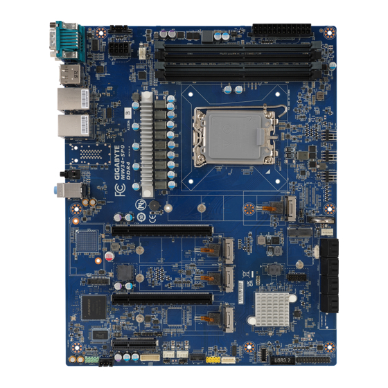
Page 5: Mw34-Sp0 Motherboard Layout
MW34-SP0 Motherboard Layout CPU1 - 5 -... - Page 6 Item Code Description Audio1 Audio Connectors SW_ID ID Button with LED USB3_MLAN Server Management LAN Port (Top)/USB 3.0 Ports (Bottom) USB3_LAN3/USB32C 2.5GbE LAN Port (Top)/USB 3.2 Type A Port (Middle) USB 3.2 Type C Port (Bottom) HDMI_DP HDMI 2.1 Port (Top)/Display Port (Bottom) COM/VGA Serial Port (Top)/Display Port (Bottom) PMBUS...
-
Page 7: Block Diagram
Block Diagram - 7 -... -
Page 8: Chapter 1 Hardware Installation
Chapter 1 Hardware Installation Installation Precautions The motherboard contains numerous delicate electronic circuits and components which can become damaged as a result of electrostatic discharge (ESD). Prior to installation, carefully read the user's manual and follow these procedures: • Prior to installation, do not remove or break motherboard S/N (Serial Number) sticker or warranty sticker provided by your dealer. -
Page 9: Product Specifications
Product Specifications NOTE: We reserve the right to make any changes to the product specifications and product-related information without prior notice. Š Form Factor 305W x 244D (mm) Š Socket Security Server Operating Properties 12th Generation Intel® Core™ processors Š 1 x LGA 1700 Socket Š... - Page 10 Š Optional TPM2.0 kit: CTM010 Š Board Aspeed® AST2600 Management Controller Š Security Socket Management GIGABYTE Management Console (AMI MegaRAC SP-X) Web Interface Š Operating Operating temperature: 10°C to 40°C Š Properties Operating humidity: 8-80% (non-condensing) Š Security Non-operating temperature: -40°C to 60°C Š...
-
Page 11: Installing And Removing The Cpu
Installing and Removing the CPU Read the following guidelines before you begin to install the CPU: • Make sure that the motherboard supports the CPU. • Always turn off the computer and unplug the power cord from the power outlet before installing the CPU to prevent hardware damage. -
Page 12: Installing And Removing Memory
Installing and Removing Memory Read the following guidelines before you begin to install the memory: • Make sure that the motherboard supports the memory. It is recommended to use memory of the same capacity, brand, speed, and chips. • Always turn off the computer and unplug the power cord from the power outlet before installing the memory to prevent hardware damage. -
Page 13: Installing And Removing A Memory Module
1-4-2 Installing and Removing a Memory Module Before installing a memory module, make sure to turn off the computer and unplug the power cord from the power outlet to prevent damage to the memory module. Be sure to install DDR4 ECC UDIMMs on this motherboard. Follow these instructions to install a UDIMM module: Insert the UDIMM memory module vertically into the UDIMM slot and push it down. -
Page 14: Installing The M.2 Ssd Module
Installing the M.2 SSD Module Follow the steps below to install a M.2 SSD module on your motherboard. Step1. Insert the M.2 SSD module into the slot. Step2. Secure it with the screw, tightening as necessary to fasten the M.2 SSD module in place. Installing and Removing the M.2 WiFi Module Follow the steps below to install a M.2 WiFi module on your motherboard. -
Page 15: Back Panel Connectors
Back Panel Connectors Serial Port Connect to serial-based mouse or data processing devices. VGA Port Connect to a monitor device. Display Port DisplayPort delivers high quality digital imaging and audio, supporting bi-directional audio transmission. Connect to a DisplayPort-supported monitor. HDMI 2.1 Port The HDMI port is HDCP 2.3 compliant and supports Dolby TrueHD and DTS HD Master Audio formats. - Page 16 Line Out Jack (Green) The default Line Out jack. Use this audio jack for a headphone or 2-channel speaker. This jack can be used to connect front speakers in a 4/5.1/7.1-channel audio configuration. Mic In Jack (Pink) The default MIC In jack. A microphone can be connected to the MIC In jack. LAN and ID Button LEDs 2.5GbE LAN LED: Link/Activity LED Speed LED State Description Yellow On 1Gps data rate Green On 2.5Gbps data rate 100Mbps data rate LAN Port 10/100/1000 LAN LED: State Description...
-
Page 17: Internal Connectors
Internal Connectors CPU1 12) F_USB2_1 P12V_CPU 13) F_USB32C_1 SATA_0_1 14) FP_1 SATA_2_3 15) BP_1 SATA_4_5 16) TPM SATA_6_7 17) IPMB SATA_SGP1/SATA_SGP2 18) CN_NCSI CPU_FAN1 19) F_AUDIO1 SYS_FAN1/2/3/4/5/6 20) LED_BMC 10) PMBUS 21) BAT1 11) F_USB3_1 22) CASE_OPEN Read the following guidelines before connecting external devices: •... - Page 18 1/2) ATX/P12V_CPU (2x12 Main Power Connector and 2x4 12V Power Connector) With the use of the power connector, the power supply can supply enough stable power to all the components on the motherboard. Before connecting the power connector, first make sure the power supply is turned off and all devices are properly installed. The power connector possesses a foolproof design. Connect the power supply cable to the power connector in the correct orientation.
- Page 19 3/4/5/6) SATA_0_1/SATA_2_3/SATA_4_5/SATA_6_7 (SATA III 6Gb/s Connectors) The SATA connectors conform to SATA III 6Gb/s standard and are compatible with SATA 3Gb/s standard. Each SATA connector supports a single SATA device. Pin No. Definition 7) SATA_SGP1/SATA_SGP2 (SATA SGPIO Connector) Serial General Purpose Input/Output (SGPIO) is a communication method used between a host bus adapter (HBA) and a main board.
- Page 20 8/9) CPU_FAN1/SYS_FAN1/SYS_FAN2/SYS_FAN3/SYS_FAN4/SYS_FAN5/SYS_FAN6 (Fan Headers) The motherboard has one 4-pin CPU fan header (CPU_FAN), and six 4-pin (SYS_FAN) system fan headers. Most fan headers possess a foolproof insertion design. When connecting a fan cable, be sure to connect it in the correct orientation (the black connector wire is the ground wire). The motherboard supports CPU fan speed control, which requires the use of a CPU fan with fan speed control design.
- Page 21 11/12) F_USB3_1/F_USB2_1 (Front Panel USB 3.2 Connector/2.0 Header) The connector/header conform to USB 2.0/ 3.0 specification. Each USB connector/header can provide two USB ports via an optional USB bracket. For purchasing the optional USB bracket, please contact the local dealer. USB 2.0 Header Pin No. Definition Pin No. Definition Power (5V) USB DY+ Power (5V) USB DX- USB DY-...
- Page 22 14) FP_1 (Front Panel Header) Connect the power switch, reset switch, speaker, chassis intrusion switch/sensor and system status indicator on the chassis to this header according to the pin assignments below. Note the positive and negative pins before connecting the cables. Pin No.
- Page 23 16) TPM (Trusted Platform Module Connector) Trusted Platform Module (TPM) is an international standard for a secure cryptoprocessor, a dedicated microcontroller designed to secure hardware through integrated cryptographic keys. 13 14 Pin No. Definition Pin No. Definition Clock P_3V3_AUX LPC_RST No Pin SPI_MISO IRQ_SPI...
- Page 24 18) CN_NCSI (NCSI Connector) Pin No. Definition Pin No. Definition NCSI_CLK NCSI_RX_D0 NCSI_RX_D1 NCSI_CRS_DV NCSI_RX_ER P3V3_AUX NCSI_TX_D1 NCSI_TX_D0 NCSI_TX_EN NCSI_PRESENT P3V3_AUX 19) F_AUDIO1 (Front Panel Audio Header) The front panel audio header supports Intel High Definition audio (HD). You may connect your chassis front panel audio module to this header. Make sure the wire assignments of the module connector match the pin assignments of the motherboard header.
- Page 25 20) LED_BMC (BMC Firmware Readiness LED) State Description BMC firmware is initial Blink BMC firmware is ready AC loss 21) BAT1 (Battery Socket) The battery provides power to keep the values (such as BIOS configurations, date, and time information) in the CMOS when the computer is turned off. Replace the battery when the battery voltage drops to a low level, or the CMOS values may not be accurate or may be lost. •...
- Page 26 22) CASE_OPEN (Case Open Intrusion Alert Header) This motherboard provides a chassis detection feature that detects if the chassis cover has been removed. This function requires a chassis with chassis intrusion detection design. Open: Normal Operation (Default) Closed: Active Chassis Intrusion Alert Hardware Installation - 26 -...
-
Page 27: Jumper Settings
Jumper Settings Enable Power On Select Default S3_MASK Default Force Update Enable ME_UPDATE BIOS Enable Recovery Default BIOS_RCVR Default Enable Password Default Clear CMOS Clear 1 2 3 Enable CLR_CMOS PASS_CLEAR Hardware Installation - 27 -... -
Page 28: Chapter 2 Bios Setup
Chapter 2 BIOS Setup BIOS (Basic Input and Output System) records hardware parameters of the system in the EFI on the motherboard. Its major functions include conducting the Power-On Self-Test (POST) during system startup, saving system parameters, loading the operating system etc. The BIOS includes a BIOS Setup program that allows the user to modify basic system configuration settings or to activate certain system features. When the power is turned off, the battery on the motherboard supplies the necessary power to the CMOS to keep the configuration values in the CMOS. - Page 29 Main This setup page includes all the items of the standard compatible BIOS. Advanced This setup page includes all the items of AMI BIOS special enhanced features. (ex: Auto detect fan and temperature status, automatically configure hard disk parameters.) Chipset This setup page includes all the submenu options for configuring the functions of the Platform Controller Hub. Server Management Server additional features enabled/disabled setup menus. ...
-
Page 30: The Main Menu
The Main Menu Once you enter the BIOS Setup program, the Main Menu (as shown below) appears on the screen. Use arrow keys to move among the items and press <Enter> to accept or enter other sub-menu. Main Menu Help The on-screen description of a highlighted setup option is displayed on the bottom line of the Main Menu. - Page 31 Parameter Description BIOS Information Project Name Displays the project name information. Project Version Displays version number of the BIOS setup utility. Build Date and Time Displays the date and time when the BIOS setup utility was created. BMC Information (Note1) BMC Firmware Version Displays BMC firmware version information. (Note1) Processor Information CPU Brand String/ Max CPU Speed Displays the technical information for the installed processor.
- Page 32 Parameter Description Onboard LAN Information LAN# MAC Address (Note) Displays LAN MAC address information. ME FW Version Displays ME Firmware version. System Language Option: English. System Date Sets the date following the weekday-month-day-year format. System Time Sets the system time following the hour-minute-second format. (Note) The number of LAN ports listed will depend on the motherboard / system model.
-
Page 33: Advanced Menu
Advanced Menu The Advanced Menu displays submenu options for configuring the function of various hardware components. Select a submenu item, then press <Enter> to access the related submenu screen. BIOS Setup - 33 -... -
Page 34: Cpu Configuration
2-2-1 CPU Configuration Parameter Description CPU Configuration Core Information Displays the core information. ID/Brand String/VMX/SMX/TXT/ Displays the technical information for the installed processor(s). CPU Flex Ratio Settings Enable/Disable this item to turn on/off the MLC streamer prefetcher. Hardware Prefetcher Options available: Disabled, Enabled. Default setting is Enabled. When enabled, cache lines are fetched in pairs. -
Page 35: Me Configuration
2-2-2 ME Configuration Parameter Description ME Firmware Version/ME Firmware Mode/ME Firmware Displays the ME firmware information. SKU/ME State Press [Enter] to configure advanced items. Me FW Image Re-Flash Š – Enable/Disable Me FW Image Re-Flash function. Firmware Update Configuration – Options available: Disabled, Enabled. Default setting is Disabled. FW Update Š –... -
Page 36: Trusted Computing
2-2-3 Trusted Computing Parameter Description Configuration Enable/Disable BIOS support for security device. OS will not show security device. TCG EFI protocol and INT1A interface will not be Security Device Support available. Options available: Enable, Disable. Default setting is Enable. BIOS Setup - 36 -... -
Page 37: Runtime Error Logging Settings
2-2-4 Runtime Error Logging Settings Parameter Description Runtime Error Logging Settings Runtime Error Logging System Enable/Disable runtime error logging system. Enabling Options available: Enabled, Disabled. Default setting is Enabled. Enable/Disable memory error enabling. Memory Error Enabling Options available: Enabled, Disabled. Default setting is Enabled. Enable/Disable PCI/PCI error enabling. -
Page 38: S5 Rtc Wake Settings
2-2-5 S5 RTC Wake Settings Parameter Description Enable/Disable system wake on alarm event. Options available: Disabled, Fixed Time. When Fixed Time is selected, Wake System from S5 system will wake on the hr::min::sec specified. Default setting is Disabled. BIOS Setup - 38 -... -
Page 39: Serial Port Console Redirection
2-2-6 Serial Port Console Redirection Parameter Description Console redirection enables the users to manage the system from a COM Console remote location. Redirection (Note) Options available: Enabled, Disabled. Default setting is Disabled. Press [Enter] to configure advanced items. Please note that this item is configurable when COM Console Redirection is set to Enabled. - Page 40 Parameter Description Parity Š – A parity bit can be sent with the data bits to detect some transmission errors. – Even: parity bit is 0 if the num of 1's in the data bits is even. – Odd: parity bit is 0 if num of 1's in the data bits is odd. –...
- Page 41 Parameter Description Legacy Console Redirection Press [Enter] to configure advanced items. Redirection COM Port Š – Selects a COM port for Legacy serial redirection. – Default setting is COM1. Resolution Š – Selects the number of rows and columns used in Console Redirection for legacy OS support. Legacy Console Redirection –...
- Page 42 Parameter Description Flow Control EMS Š – Flow control can prevent data loss from buffer overflow. When sending data, if the receiving buffers are full, a 'stop' signal can Serial Port for Out-of-Band be sent to stop the data flow. Once the buffers are empty, a 'start' EMS Console Redirection signal can be sent to re-start the flow. Hardware flow control uses Settings(continued) two wires to send start/stop signals. – Options available: None, Hardware RTS/CTS, Software Xon/Xoff. Default setting is None.
-
Page 43: Sio Configuration
2-2-7 SIO Configuration Description Parameter Displays the AMI SIO driver version information. AMI SIO Driver Version Super IO Chip Logical Device(s) Configuration Press [Enter] to configure advanced items. Use This Device Š – When set to Enabled allows you to configure the serial port settings. When set to Disabled, displays no configuration for the serial port. –... -
Page 44: Usb Configuration
2-2-8 USB Configuration Parameter Description USB Configuration USB Devices: Displays the USB devices connected to the system. Enable/Disable the XHCI (USB 3.0) Hand-off support. XHCI Hand-off Options available: Disabled, Enabled. Default setting is Enabled. USB hardware delays and time-outs Select the time-out value for USB Control/Bulk/Interrupt transfers. USB transfer time-out Options available: 1 sec, 5 sec, 10 sec, 20 sec. -
Page 45: Network Stack Configuration
2-2-9 Network Stack Configuration Parameter Description Enable/Disable the UEFI network stack. Network Stack Options available: Enabled, Disabled. Default setting is Enabled. Enable/Disable the Ipv4 PXE feature. Ipv4 PXE Support Options available: Enabled, Disabled. Default setting is Enabled. Enable/Disable the Ipv4 HTTP feature. Ipv4 HTTP Support Options available: Enabled, Disabled. -
Page 46: Csm Configuration
2-2-10 CSM Configuration Parameter Description Compatibility Support Module Configuration CSM Support (Note) Options available: Enabled, Disabled. Default setting is Disabled. Options available: UEFI and Legacy, Legacy only, UEFI only. Default setting Boot option filter is UEFI and Legacy. Option ROM execution - Network/Storage/Video/ Options available: Do not launch, UEFI, Legacy. -
Page 47: Offboard Sata Controller Configuration
2-2-11 Offboard SATA Controller Configuration Parameter Description Offboard SATA Controller Displays the information on your PCIe SATA controllers/ PCIe SSD if Configuration installed. BIOS Setup - 47 -... -
Page 48: Whea Configuration
2-2-12 WHEA Configuration Parameter Description Enable/Disable Windows Hardware Error Architecture. WHEA Support Options available: Disabled, Enabled. Default setting is Enabled. BIOS Setup - 48 -... -
Page 49: Chipset Configuration
2-2-13 Chipset Configuration Parameter Description Defines the power state to resume to after a system shutdown that is due to an interruption in AC power. When set to Last State, the system will return to the active power state prior to shutdown. When set to Restore on AC Power Loss (Note) Power Off, the system remains off after power shutdown. Options available: Last State, Power Off, Power On, Unspecified. The default setting depends on the BMC setting. -
Page 50: Tls Auth Configuration
2-2-14 Tls Auth Configuration Parameter Description Press [Enter] for configuration of advanced items. Enroll Cert Š – Press [Enter] to enroll a certificate • Enroll Cert Using File • Cert GUID Server CA Configuration Input digit character in 1111111-2222-3333-4444-1234567890ab format. – Commit Changes and Exit – Discard Changes and Exit Delete Cert Š Press [Enter] for configuration of advanced items. Client Cert Configuration BIOS Setup - 50 -... -
Page 51: Iscsi Configuration
2-2-15 iSCSI Configuration Parameter Description Press [Enter] configure advanced items. Attempt Priority Š Attempt Priority – Options available: Host Attempt, Redfish Attempt. Default setting is Host Attempt. Commit Changes and Exit Š Press [Enter] to configure advanced items. iSCSI Initiator Name Š – Only IQN format is accepted. Range: from 4 to 223 Host iSCSI Configuration Add an Attempt Š... -
Page 52: Intel(R) Ethernet Controller I225-V
2-2-16 Intel(R) Ethernet Controller I225-V Description Parameter Displays the technical specifications for the Network Interface Controller. UEFI Driver Displays the technical specifications for the Network Interface Controller. Device Name Displays the technical specifications for the Network Interface Controller. PCI Device ID Displays the technical specifications for the Network Interface Controller. Link Status Displays the technical specifications for the Network Interface Controller. MAC Address BIOS Setup - 52 -... -
Page 53: Driver Health
2-2-17 Driver Health Parameter Description Driver Health Displays driver health status of the devices/controllers if installed. BIOS Setup - 53 -... -
Page 54: Chipset Menu
Chipset Menu Chipset Setup menu displays submenu options for configuring the function of Platform Controller Hub(PCH). Select a submenu item, then press <Enter> to access the related submenu screen. BIOS Setup - 54 -... -
Page 55: System Agent (Sa) Configuration
2-3-1 System Agent (SA) Configuration Parameter Description Press [Enter] to configure advanced items. Memory Š – Press [Enter] to view/configure memory overclocking menu. Memory Configuration Š Memory Frequency Š – Displays the frequency information of installed memory. Controller#Channel#slot# information of memory DIMMs. Š Memory Configuration Maximum Memory Frequency Š Default setting is Auto. –... - Page 56 Parameter Description Internal Graphics Š – Options available: Auto, Disabled, Enabled. Default setting is Enabled. GTT Size Š Options available: 2MB, 4MB, 8MB. Default setting is 8MB. – Aperture Size Š – Options available: 128MB, 256MB, 512MB, 1024MB. Default setting is 256MB. Graphics Configuration PSMI SUPPORT Š...
- Page 57 Parameter Description Enable/Disable VT-d capability. VT-d Options available: Enabled, Disabled. Default setting is Enabled. Enable/Disable IOMMU in Pre-boot environment. Control Iommu Pre-boot Behavior Options available: Disable IOMMU, Enable IOMMU during boot. Default setting is Enable IOMMU during boot. X2APIC Opt Out Options available: Enabled, Disabled.
-
Page 58: Pch-Io Configuration
2-3-2 PCH-IO Configuration Parameter Description Press [Enter] to configure advanced items. SATA Controller(s) Š – Enable/Disable SATA device. – Options available: Enabled, Disabled. Default setting is Enabled. SATA Mode Selection Š SATA Configuration – Default setting is AHCI. SATA Test Mode Š – Options available: Enabled, Disabled. Default setting is Disabled. Aggressive LPM Support Š... -
Page 59: Server Management Menu
Server Management Menu Parameter Description Enable/Disable FRB-2 timer (POST timer). FRB-2 Timer Options available: Enabled, Disabled. Default setting is Disabled. Configures the FRB2 Timer timeout. FRB-2 Timer Options available: 3 minutes, 4 minutes, 5 minutes, 6 minutes. Default setting is 6 timeout (Note1) minutes. Configures the FRB2 Timer policy. - Page 60 Parameter Description System Event Log Press [Enter] to configure advanced items. View FRU Press [Enter] to view the FRU information. Information BMC network Press [Enter] to configure advanced items. Configuration IPv6 BMC Network Press [Enter] to configure advanced items. Configuration BIOS Setup - 60 -...
-
Page 61: System Event Log
2-4-1 System Event Log Parameter Description Enabling / Disabling Options Change this item to enable or disable all features of System Event SEL Components Logging during boot. Options available: Enabled, Disabled. Default setting is Enabled. Erasing Settings Choose options for erasing SEL. Options available: No Erase SEL Yes, On next reset... -
Page 62: View Fru Information
2-4-2 View FRU Information The FRU page is a simple display page for basic system ID information, as well as System product information. Items on this window are non-configurable. (Note) The model name will vary depends on the product you purchased BIOS Setup - 62 -... -
Page 63: Bmc Network Configuration
2-4-3 BMC Network Configuration Parameter Description BMC network configuration Lan Channel 1 Selects to configure LAN channel parameters statically or dynamically (by BIOS or BMC). Configuration Address source Options available: Unspecified, Static, DynamicBmcDhcp, DynamicBmcNonDhcp. Default setting is Unspecified. Current Configuration Address Display the current configuration information. Source Station IP address Displays IP Address information. Subnet mask Displays Subnet Mask information. Station MAC address Displays the MAC Address information. -
Page 64: Ipv6 Bmc Network Configuration
2-4-4 IPv6 BMC Network Configuration Parameter Description IPv6 BMC network configuration IPv6 BMC Lan Channel 1 Enable/Disable IPv6 BMC LAN channel function. When this item is disabled, the system will not modify any BMC network during BIOS IPv6 BMC Lan Option phase. Options available: Unspecified, Disable, Enable. Default setting is Enable. -
Page 65: Security Menu
Security Menu The Security menu allows you to safeguard and protect the system from unauthorized use by setting up access passwords. There are two types of passwords that you can set: • Administrator Password Entering this password will allow the user to access and change all settings in the Setup Utility. •... -
Page 66: Secure Boot
2-5-1 Secure Boot The Secure Boot submenu is applicable when your device is installed the Windows 8 (or above) operating ® system. Parameter Description System Mode Displays if the system is in User mode or Setup mode. Enable/ Disable the Secure Boot function. Secure Boot Options available: Enabled, Disabled. - Page 67 Parameter Description Press [Enter] to configure advanced items. Please note that this item is configurable when Secure Boot Mode is set to Custom. Factory Key Provision Š – Allows to provision factory default Secure Boot keys when system is in Setup Mode. – Options available: Enabled, Disabled. Default setting is Disabled. Restore Factory Keys Š...
- Page 68 Parameter Description Export Secure Boot variables Š – Copy NVRAM content of Secure Boot variables to files in a root folder Key Management on a file system device. (continued) Enroll Efi Image Š – Press [Enter] to enroll SHA256 hash of the binary into Authorized Signature Database (db). BIOS Setup - 68 -...
-
Page 69: Boot Menu
Boot Menu The Boot menu allows you to set the drive priority during system boot-up. BIOS setup will display an error message if the legacy drive(s) specified is not bootable. Parameter Description Boot Configuration Number of seconds to wait for setup activation key. 65535 (0xFFFF) Setup Prompt Timeout means indefinite waiting. Press the numeric keys to input the desired values. - Page 70 Parameter Description FIXED BOOT ORDER Priorities Press [Enter] to configure the boot priority. By default, the server searches for boot devices in the following sequence: Hard drive. Boot Option #1 / #2 / #3 / #4 / #5 CD-COM/DVD drive. USB device. Network. UEFI. BIOS Setup - 70 -...
-
Page 71: Save & Exit Menu
Save & Exit Menu The Save & Exit menu displays the various options to quit from the BIOS setup. Highlight any of the exit options then press <Enter>. Parameter Description Save Options Restarts the system after saving the changes made. Save Changes and Reset Options available: Yes, No. -
Page 72: Bios Recovery
BIOS Recovery The system has an embedded recovery technique. In the event that the BIOS becomes corrupt the boot block can be used to restore the BIOS to a working state. To restore your BIOS, please follow the instructions listed below: Recovery Instruction: 1. -
Page 73: Bios Post Beep Code (Ami Standard)
BIOS POST Beep code (AMI standard) 2-9-1 PEI Beep Codes # of Beeps Description Memory not Installed. Memory was installed twice (InstallPeiMemory routine in PEI Core called twice) Recovery started DXEIPL was not found DXE Core Firmware Volume was not found Recovery failed S3 Resume failed Reset PPI is not available...
Need help?
Do you have a question about the MW34-SP0 and is the answer not in the manual?
Questions and answers