Table of Contents

Related Manuals for ORTAL Enervex RS Series

Summary of Contents for ORTAL Enervex RS Series
- Page 1 Installation and Operation Manual Enervex RS Series Power Vent System Enervex RS Series Power Vents: RS 009 Power Vent RS 012 Power Vent RS 014 Power Vent RS 016 Power Vent Ortal Enervex Power Vent Installation Manual (V2.0)
-
Page 2: General
WARNING: MATERIAL USAGE All materials and objects used to carry out the installation must be certified/approved or specified by Ortal and are suitable for use. Do NOT install the system with different materials or objects than those approved for installation by Ortal. -
Page 3: Table Of Contents
This manual applies to the Enervex RS Series Power Vent System and approved venting only. It is to be used along with the applicable Ortal fireplace installation manual for the installation of the fireplace and remaining components. -
Page 4: Power Vent Kit Components
High-Voltage Relay: The High-Voltage Relay makes the electrical connection between the Enervex ADC100 and the Ortal ... - Page 5 The following table shows the standard Enervex Power Vent Kit options and components Ortal supplies. For fan sizes larger than the RS 009, please contact Ortal. Kit SKU Kit Description Components Vent Pipe Size RS 009 Power Vent Fan 4x6 Enervex Power Vent Kit for...
-
Page 6: Venting
BDM: Pro-Form Direct Vent System 5x8 co-axial direct vent pipe Selkirk: Direct-Temp System (8-inch diameter) Curve NOTE: If your vent configuration exceeds 120 feet in total length, contact Ortal to determine which of the larger fans (RS012-016) would work best. -
Page 7: Pre-Installation Considerations
Pre-Installation Considerations IMPORTANT: Read Before You Begin Take the following information into consideration when planning the vent configuration/pathway for your project. Vertical Drop: The vent configuration cannot exceed 6 feet of cumulative vertical drop (downhill run). For venting that rises vertically after a drop, a condensation drain must be installed mid-way though the horizontal portion of the drop. -
Page 8: Power Vent System
RS 016 fan models, the Enervex RS 009 fan is the standard fan offered in the Enervex Power Vent Kits. It covers most project venting needs. If your vent configuration exceeds the RS 009 model capabilities, contact Ortal to determine which larger fan would work best. -
Page 9: Wiring Diagrams
Wiring Diagrams The following diagrams show the electrical wiring required to connect the Enervex and Ortal system. Wiring Diagram: Screen Fireplace with Enervex Power Vent... - Page 10 Wiring Diagram: Double Glass Fireplace with Enervex Power Vent...
-
Page 11: Components
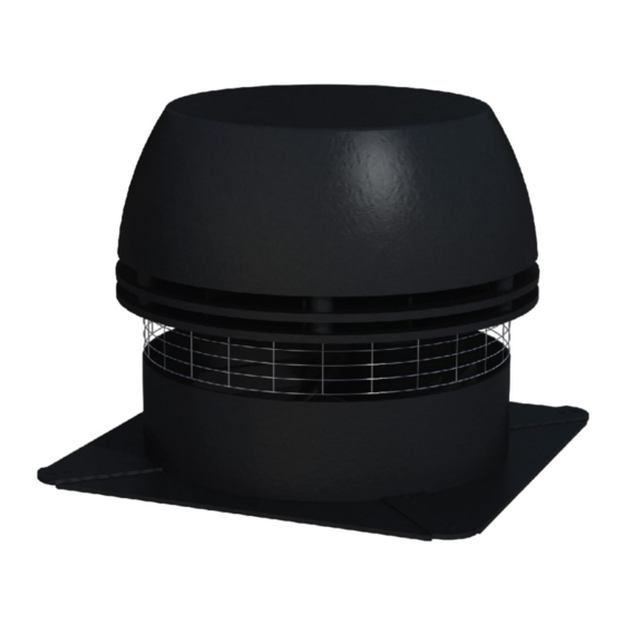
Components RS Series Power Vent Specifications The RS Series Power Vent Fan connects directly to the vent pipe and is mounted at the termination location. The air intake and exhaust for the fireplace are taken in and expelled out here. The following specifications were taken from page 5 of the Enervex RS Chimney Fan Installation Manual. - Page 12 Pre-Installation Considerations The following instructions were taken from page 6 of the Enervex RS Chimney Fan Installation Manual.
- Page 13 Installation The following instructions were taken from pages 7-9, 10 of the Enervex RS Chimney Fan Installation Manual. NOTE: Because the fireplace uses co-axial direct vent pipe, a special vent adapter (supplied) and must be attached to the power vent before the power vent is installed.
- Page 14 NOTE: Because the fireplace uses co-axial direct vent pipe, a special vent adapter (supplied) and must be attached to the power vent before the power vent is installed.
- Page 15 NOTE: Because the fireplace uses co-axial direct vent pipe, a special vent adapter (supplied) and must be attached to the power vent before the power vent is installed.
- Page 16 Startup The following instructions were taken from page 14 of the Enervex RS Chimney Fan Installation Manual.
- Page 17 Clearances Vertical Termination Maintain clearances as described below. A - when exhaust is facing A - when exhaust is toward away from an intake side an intake side 12” min up to 24” 12” min up to 24” 18” min 24”...
- Page 18 Horizontal Termination Location Country Minimum Clearance Description Clearance above grade, veranda, porch, deck, or balcony. US & 12 inches NOTE: On private property where termination is less than 7 feet above a sidewalk, driveway, Canada deck, porch, veranda, or balcony, use of a listed cap shield is suggested. ...
- Page 19 Covered Alcove: spaces open only on one side and with an overhang Horizontal Termination Clearances Continued: Covered Alcove Application Location Country Minimum Clearance Description Clearance under non-vinyl veranda, porch, deck, balcony, or overhang. NOTE: Termination in a covered alcove space is permitted with the dimensions specified. 1.
-
Page 20: Adc 100 Control Box
ADC 100 Control Box Specifications The ADC 100 Control Box controls the speed of the power vent fan to maintain proper draft and pressure in a vent system. The ADC 100 control comes with a Proven Draft Switch (the PDS1) and a Chimney Probe. The PDS and Chimney Probe are a required safety function used to ensure a negative pressure is maintained in the vent pipe. - Page 21 Installation The following installation instructions were taken from pages 6-9 and 13-15 of the Enervex ADC 100 Fan Control Installation Manual.
- Page 22 NOTE: Ortal fireplaces do not use a damper.
- Page 25 Startup...
-
Page 28: Proven Draft Switch And Chimney Probe
Proven Draft Switch and Chimney Probe Specifications The Proven Draft Switch (PDS1) and Chimney Probe create a safety mechanism that monitors the pressure inside the vent pipe. In the event Chimney Probe measures a pressure drop in the vent pipe, the PDS1 will communicate with the ADC 100 and shut off the supply of gas to the fireplace. - Page 29 Installation The following installation instructions were taken from pages 5-7 of the Enervex PDS Fan Proving Switch Installation Manual.
- Page 30 Startup...
-
Page 31: Gas Solenoid Valve
Gas Solenoid Valve Specifications The Gas Solenoid Valve is a safety mechanism that regulates the flow of gas to the fireplace. In the event that pressure in the vent pipe drops below normal limits, the gas solenoid will shut off the gas going to the fireplace. Features 2-way normally closed operation ... - Page 32 Installation The following instructions were taken from pages 1-2 of the ASCO Valve Manual.
-
Page 34: Electrical
Power is supplied to the power vent fan from the ADC 100 control box. The power cable for the ADC 100 control box and the fireplace AC Adapter may be plugged into a duplex receptacle (2 outlets). This requirement is already called out in the Ortal fireplace manual. -
Page 35: Wiring Diagrams
Wiring Diagrams The following diagrams show the electrical wiring required to connect the Enervex and Ortal system. NOTE: These wiring diagrams are identical to the wiring diagrams on pages 9-10. Wiring Diagram: Screen Fireplace with Enervex Power Vent... - Page 36 Wiring Diagram: Double Glass Fireplace with Enervex Power Vent...
-
Page 37: Operation
Operation An Ortal fireplace equipped with an Enervex RS Power Vent System is operated in the same manner as a standard Ortal fireplace, including remote controlled on/off and flame control. Basic operation for the 10-Button Remote Control Handset is provided below. -
Page 38: Operating Instructions
Operating Instructions Instructions for operating the 10-Button Handset are shown below. For more in-depth instructions, please refer to the “Homeowner’s Fireplace Operation Manual” or “Remote Operation Instructions”. NOTE: Some options on the remote may not be available for all fireplaces. Turning the Fireplace On 1. -
Page 39: Troubleshooting
Troubleshooting RS Series Power Vent Fan The following instructions were taken from pages 16-17 of the Enervex RS Chimney Fan Installation Manual. -
Page 40: Adc 100 Control Box
RS Power Vent Fan Observation Problem Solution The circuit breaker may be off. Check the circuit breaker. There is no power going to the fan. Fan speed control is off. Turn fan speed control on. Bad electrical connections. Check and correct problem. Check and correct problems with connections. -
Page 41: Gas Solenoid
Gas Solenoid The following instructions were taken from page 2 of the Valvate ASCO Valve Manual. PREVENTATIVE MAINTENANCE Keep medium flowing through valve as free from dirt and foreign material as possible. While in service, operate valve at least once a month to ensure proper opening and closing. Periodic inspection (depending on media and service conditions) of internal valve parts for damage or excessive wear is recommended. - Page 42 © Ortal 2022 Version 2.0, January 2022 SKU: KPMANENERVEXPV2.0 Ortal USA 8421 Canoga Ave Canoga Park, CA 91304 T: (818) 238-7000 | F: (818) 678-0541 info@ortalheat.com | www.ortalheat.com...
Need help?
Do you have a question about the Enervex RS Series and is the answer not in the manual?
Questions and answers