Table of Contents
Advertisement
Quick Links
Instructions
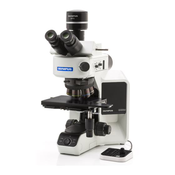
BX53M
System Microscope
This instruction manual is for the system microscope model BX53M.
Optical Microscope and Accessory
To ensure the safety, obtain optimum performance and to familiarize yourself fully with
the use of this system, we recommend that you study this manual thoroughly before
operating this system, and always keep this manual at hand when operating this system.
Retain this instruction manual in an easily accessible place near the work desk for future
reference.
For details of products included in the configuration of this system, see page 9.
Advertisement
Table of Contents

Related Manuals for Olympus BX53M


Summary of Contents for Olympus BX53M
- Page 1 Instructions BX53M System Microscope This instruction manual is for the system microscope model BX53M. Optical Microscope and Accessory To ensure the safety, obtain optimum performance and to familiarize yourself fully with the use of this system, we recommend that you study this manual thoroughly before operating this system, and always keep this manual at hand when operating this system.
- Page 2 Refer to your local Olympus distributor in EU for return and/or collection systems available in your country. NOTE: This product has been tested and found to comply with the limits for a Class A digital device, pursuant to Part 15 of the FCC Rules.
-
Page 3: Table Of Contents
Contents Introduction ............................... 1 Safety precautions ............................2 1 Nomenclature of units ........................8 2 List of combinable units ........................9 3 Basic operations of the microscope (brightfield observation) .....14 3-1 Reflected light brightfield observation procedures ............14 3-2 Turning ON the main switch ........................16 3-3 Selecting the illumination.........................16 Changing between the reflected light illumination and the transmitted light illumination ....................................... - Page 4 Method to find the approximate focal point easily ..................25 3-9 Adjusting the brightness ........................... 26 When the LED lamp housing is combined ......................26 When the halogen lamp housing is combined ....................26 When the mercury lamp housing is combined ....................26 When the light source is combined ..........................26 Using the LIM/SET switch ..............................27 3-10 Adjusting the observation tube ......................
- Page 5 3-17 Inserting the transmitted light illumination filter ..............50 4 Various observation methods ....................52 4-1 Reflected light darkfield observation procedures ............. 52 4-2 Reflected light simple polarization observation procedures ........53 Reflected light differential interference contrast (DIC) observation procedures.....................................54 4-4 Reflected light fluorescence observation procedures ..........
- Page 6 5 Troubleshooting ............................ 70 5-1 Optical systems ............................... 70 5-2 Electrical systems ............................74 5-3 Coarse/fine focusing ..........................84 5-4 Observation tube ............................84 5-5 Stage ..................................85 6 Specifications ............................86 7 Optical performance list <<UIS2 series>> ................89 8 Assembly ..............................93 8-1 Assembly diagram ............................
-
Page 7: Introduction
UIS2 (UIS) optical system series. Using inappropriate units restricts the performance. (There are units usable with the BX series. Contact Olympus or refer to the latest version of catalogs.) Configuration of instruction manuals Read all the instruction manuals provided with the units you purchased. -
Page 8: Safety Precautions
Safety precautions If the product is used in a manner not specified by this manual, the safety of the user may be imperiled. In addition, the product may also be damaged. Always use the product according to this instruction manual. The following symbols are used in this instruction manual. - Page 9 BX53M CAUTION - Electric safety - Always use the power cord provided by Olympus. If the proper AC adapter, the power cord and other cables are not used, the electric safety and the EMC (Electro- Magnetic Compatibility) performance of the product cannot be assured. If no power cord is provided, please select the proper power cord by referring to the section “Proper selection of the power cord”...
- Page 10 CAUTION - LED (light emitting diode) - Do not look directly at the light from the LED light source for a long time. The LED built in this product is basically eye-safe. However, do not look directly at the light from the LED lamp house for a long time, since it may cause damage to your eyes.
- Page 11 BX53M CAUTION - Halogen lamp housing / Mercury lamp housing - Confirm that the lamp is attached properly and cords are connected properly. Remove the power cord from the product when replacing the lamp. To avoid electric shock hazards and burns when replacing the lamp, set the...
- Page 12 Interference contrast filter (U-25IF550) / High temperature L42 filter (U-25L42) / Light balancing filter (U-25LBD) / Yellow filter (U-25Y48) / Empty slider (U-25) / Light balancing amber filter (U-25LBA) When caution labels are dirty or peeled off, contact Olympus for replacement or inquiries.
- Page 13 · If there is any possibility that you have inhaled mercury steam, consult the doctor immediately and follow his/ her instructions. 6. The used mercury burner must be disposed of as the industrial waste. If you cannot dispose of it by yourself properly, contact Olympus for assistance.
-
Page 14: Nomenclature Of Units
Nomenclature of units The diagram shown in this section shows the major units only. For units combinable to this product, see "2 List of combinable units" (page 9). Observation tube Illuminator Eyepiece Light source for reflected light illumination Fluorescence mirror unit MIX slider / DIC slider for Microscope frame reflected light observation... -
Page 15: List Of Combinable Units
BX53M List of combinable units : Combination available (including units with restrictions) : Combination prohibited : Unnecessary for observation Reflected light Transmitted light Observation Brightfield/ Differential method Simple Simple darkfield interfer- Fluores- Polariza- Brightfield Darkfield polariza- Infrared Brightfield polariza- Units... - Page 16 : Combination available (including units with restrictions) : Combination prohibited : Unnecessary for observation Reflected light Transmitted light Observation Brightfield/ Differential method Simple Simple darkfield interfer- Fluores- Polariza- Brightfield Darkfield polariza- Infrared Brightfield polariza- Units simultane- ence cence tion tion tion ously contrast...
- Page 17 BX53M : Combination available (including units with restrictions) : Combination prohibited : Unnecessary for observation Reflected light Transmitted light Observation Brightfield/ Differential method Simple Simple darkfield interfer- Fluores- Polariza- Brightfield Darkfield polariza- Infrared Brightfield polariza- Units simultane- ence cence tion...
- Page 18 : Combination available (including units with restrictions) : Combination prohibited : Unnecessary for observation Reflected light Transmitted light Observation Brightfield/ Differential method Simple Simple darkfield interfer- Fluores- Polariza- Brightfield Darkfield polariza- Infrared Brightfield polariza- Units simultane- ence cence tion tion tion ously contrast...
- Page 19 BX53M : Combination available (including units with restrictions) : Combination prohibited : Unnecessary for observation Reflected light Transmitted light Observation Brightfield/ Differential method Simple Simple darkfield interfer- Fluores- Polariza- Brightfield Darkfield polariza- Infrared Brightfield polariza- Units simultane- ence cence tion...
-
Page 20: Basic Operations Of The Microscope (Brightfield Observation)
Basic operations of the microscope (brightfield observation) This section describes the operating procedures of the reflected light brightfield observation and the transmitted light brightfield observation, which is the basis of observation methods. The reflected light simple polarization observation and the reflected light differential interference contrast observation, etc. are described in "4 Various observation methods". 3-1 Reflected light brightfield observation procedures Main switch (page 16) - Page 21 BX53M 8 13 Make a copy of this observation method guide. Place it near the microscope so that you use it when operating the microscope.
-
Page 22: Turning On The Main Switch
3-2 Turning ON the main switch Set the main switch of the microscope frame to (ON). When the power is ON, the pilot indicator a turns ON. In addition, the beep sound is heard once if the control box (BX3M-CB) is combined. If following units are combined, set the main switch of respective unit to (ON). -
Page 23: Selecting The Observation Method
BX53M 3-4 Selecting the observation method When BX3M-RLAS-S is combined Select the observation method with the observation method selector knob. Display Function The brightfield observation is selected. The darkfield observation is selected. The differential interference contrast DIC/PO observation or the polarization observation is selected. -
Page 24: When Bx3M-Uras-S Is Combined
When BX3M-URAS-S is combined Turn the turret to select the observation method. You can check which No. selects which observation method by the inscription pocket a . Note that the indicator sheet should be inserted properly in the inscription pocket when attaching the mirror unit. -
Page 25: Changing Between The Eyepiece Light Path And The Camera Light Path
BX53M 3-5 Changing between the eyepiece light path and the camera light path You can select the light path for observing with the eyepiece or the light path for observing with the display, etc. through the camera. Slide the light path selection lever of the trinocular tube to select the light path. -
Page 26: Adjusting The Stage Height
Place the sample on the stage plate or the holder plate before observation. · If the sample is not flat and/or parallel, the reflected light does not return to the objective and you cannot perform the observation. · If you observe the large-size sample, remove the stage plate and place the sample on the stage directly. -
Page 27: Using The Y-Axis Lock
BX53M Using the Y-axis lock The Y-axis lock is the function available only with the stages U-SIC64 and U-SIC4R2/SIC4L2. If you lock the Y-axis lock lever in the arrow direction, the stage movement in Y-axis direction (front and back) is locked and you can move the stage only in the X-axis direction (right to left). - Page 28 If it is too tight to raise the Y-axis knob b in , lock the stage movement with the Y-axis lock lever e once, and turn the Y-axis knob b to raise the Y-axis knob. Stage knob rubber (option) Fitting this knob rubber to the X-axis knob and/or Y-axis knob of the stage U-SVRM/SVLM and/or U-SIC64 prevents knobs from slipping and allows the fine stage operation only by holding it lightly.
-
Page 29: Selecting The Objective
BX53M 3-7 Selecting the objective When selecting the objective, be careful not to collide with NOTE the sample. When the manual or coded nosepiece is combined Turn the nosepiece to select the objective. When the motorized nosepiece is combined Press the button of the hand switch for motorized nosepiece (BX3M- HSRE) to select the objective. -
Page 30: Focusing
3-8 Focusing Moving the stage vertically Turn the coarse focusing knob a and the fine focusing knob b in the arrow direction to move the stage upward. (The sample approaches the objective.) Replacing the fine focusing knob The fine focusing knob is attached on the right side as a NOTE factory default. -
Page 31: Setting The Movement Limit With The Coarse Focusing Knob
BX53M Setting the movement limit with the coarse focusing knob This function prevents the collision between the sample and the objective and also simplifies the focusing. After the sample is brought into focus by the coarse focusing knob, if you turn the pre-focusing lever a in the arrow direction to lock it, the upper limit of the coarse focusing knob is set at the locked position. -
Page 32: Adjusting The Brightness
3-9 Adjusting the brightness When the LED lamp housing is combined Turn the brightness control knob of the microscope frame a clockwise to increase the brightness of the illumination. When the halogen lamp housing is combined Turn the brightness control knob a of the halogen lamp power supply unit (TH4) to MAX (high voltage side) to increase the brightness of the illumination. -
Page 33: Using The Lim/Set Switch
BX53M Using the LIM/SET switch This function is available when the unit is combined in the following combination state. · LED lamp housing, motorized or coded nosepiece and coded reflected light illuminator* · LED lamp housing and motorized or coded nosepiece ·... - Page 34 Procedure to replay the brightness Press the LIM switch a to set the "Replay" mode. (The LIM indicator b is ON.) When the desired objective or the observation method is selected, the stored brightness is set automatically. Example of the stored brightness When you press the SET switch d when units are combined and set as follows, the brightness corresponding to in the tables...
- Page 35 BX53M Combination example 2 Combination example 4 Unit Setting Unit Setting Reflected LED lamp housing (BX3M-LEDR) Reflected light Transmitted Reflected LED lamp housing (BX3M-LEDR) Transmitted LED lamp housing (BX3M-LEDT) illumination light Transmitted LED lamp housing (BX3M-LEDT) illumination Reflected light illuminator for BF/DF –...
- Page 36 Restoring the stored brightness (LIM function) to the factory default setting Set the main switch of the microscope frame to (OFF). If the control box is combined, remove it. Set the main switch of the microscope frame to (ON) while pressing both the LIM switch a and the SET switch b .
-
Page 37: Adjusting The Observation Tube
BX53M 3-10 Adjusting the observation tube Tilting adjustment This function is available when U-TBI-3, U-TTR-2 or U-SWETTR-5 is combined. You can adjust the observation tube to the easy-to-see height and angle so that you can observe with a comfortable posture. -
Page 38: Adjusting The Interpupillary Distance
Adjusting the interpupillary distance The adjustment of the interpupillary distance is to adjust the distance between two eyepieces to fit to the distance between your two eyes. By doing so, you can see the single microscope image so that the fatigue of your eyes during observation can be reduced. - Page 39 BX53M When the eyepiece is equipped with the eyepiece micrometer While looking into the eyepiece equipped with the eyepiece micrometer, turn the diopter adjustment ring b to adjust so that the scales or lines of the eyepiece micrometer in the field of view are clearly visible.
-
Page 40: Adjusting The Field Diaphragm Of The Reflected Light Illumination
3-11 Adjusting the field diaphragm of the reflected light illumination Using the field diaphragm (FS) When BX3M-RLAS-S or BX3M-URAS-S is combined Move the field diaphragm knob a of the reflected light illuminator vertically to adjust the field diaphragm. Field diaphragm knob position Field Open to Close to... -
Page 41: Adjusting During Observation
BX53M When BX3M-URAS-S is combined Image sensor 1/3.2 1/2.5 1/1.8 inch size inch inch 1 inch Camera 2/3 inch 1/3 inch 1/2 inch adapter 0.5X 0.63X · If the field diaphragm is not centered, the area around the NOTE field of view may be darkened partially. For the centering of the field diaphragm, see "Centering of the field diaphragm... -
Page 42: Centering Of The Field Diaphragm (Fs)
Centering of the field diaphragm (FS) When centering the field diaphragm, be careful not to NOTE touch the X-axis and Y-axis of the stage with your arm. Use the Allen screwdriver provided with the microscope to perform the centering. Select the brightfield observation (BF). For procedures to select the observation method, see "3-4 Selecting the observation method"... - Page 43 BX53M BX3M-RLAS-S, BX3M-URAS-S BX3M-RLA-S Move the field diaphragm knob (field diaphragm lever) t o o p e n t h e f i e l d d i a p h r a g m i m a g e u n t i l t h e f i e l d diaphragm image inscribes to the field of view.
-
Page 44: Adjusting The Aperture Diaphragm Of The Reflected Light Illumination
3-12 Adjusting the aperture diaphragm of the reflected light illumination Using the aperture diaphragm (AS) When BX3M-RLAS-S or BX3M-URAS-S is combined Move the aperture diaphragm knob a of the reflected light illuminator vertically to adjust the aperture diaphragm. Aperture diaphragm knob position (color bar) None Red/ Light... -
Page 45: Adjusting During Observation
BX53M Adjusting during observation Reflected light brightfield observation When using BX3M-RLA-S, narrow down the aperture diaphragm to between 70 and 80% of the numerical aperture of the objective to perform the excellent observation. Aperture diaphragm image Reflected light darkfield observation / Reflected light fluorescence observation Open the aperture diaphragm during the observation. -
Page 46: Centering The Mercury Burner
3-13 Centering the mercury burner The centering of the mercury burner is necessary when U-LH100HG/U-LH100HGAPO is combined with the system. The mercury burner emits the light by means of discharge produced when a current is supplied across electrodes. If the electrode position is shifted to cause the light not falling on the sample appropriately due to replacing the burner, etc., the observation image becomes dark. - Page 47 BX53M 10 12 Turn the collector lens focusing knob to project the arc image on U-CST. (Picture A) If the arc image is not projected, turn the burner centering knobs. Turn the burner centering knobs to move the arc image to the center of the right (left) half of the field of view.
-
Page 48: Inserting The Reflected Light Illumination Filter
3-14 Inserting the reflected light illumination filter Using the ND filter lever This function is available only with BX3M-RLA-S. The ND filter links with the selection of the observation method. Using this ND filter reduces the glare when the light path is changed from the darkfield (DF) to the brightfield (BF). -
Page 49: Using The Filter
(Band-pass filters for IR) observation U-BP1200IR Filter for IR (wavelength: 1200 nm) (Band-pass filters for IR) observation Empty slider Used by combining arbitrary filters. U-25 If you want to insert the filter from the right side of the reflected light illuminator, contact Olympus. - Page 50 Attaching the arbitrary filter The arbitrary filter with the following size can be inserted to the empty slider (U-25). Diameter Ø25 mm Thickness 2.6 mm or less Set the display surface of the empty slider facing down and the surface attached with the cover facing up.
- Page 51 BX53M MEMO...
-
Page 52: Transmitted Light Brightfield Observation Procedures
3-15 Transmitted light brightfield observation procedures Main switch (page 16) Turn ON the main switch. Transmitted/reflected light switch (page 16) Select the transmitted light illumination Observation method selector knob of the Select the brightfield (BF) observation. reflected light illuminator (page 17) Brightness control knob of the microscope Adjust the brightness. - Page 53 BX53M 4 15 Make a copy of this observation method guide. Place it near the microscope so that you use it when operating the microscope.
-
Page 54: Adjusting The Field Diaphragm Of The Transmitted Light Illumination
3-16 Adjusting the field diaphragm of the transmitted light illumination Using the field diaphragm (FS) This function is available only with the microscope frame (BX53MTRF-S). Turn the field diaphragm ring a to adjust the field diaphragm. Field diaphragm ring index position Field Open to Close to... - Page 55 BX53M Field diaphragm image Turn the condenser height adjustment knob to bring the field diaphragm image into focus. (Picture A) Field of view of the eyepiece Turn the centering knobs (2 positions) to adjust the field diaphragm image to come to the center of the field. (Picture B) Turn the field diaphragm ring in the arrow direction to open the field diaphragm gradually until the field diaphragm image inscribes the field of view.
-
Page 56: Inserting The Transmitted Light Illumination Filter
3-17 Inserting the transmitted light illumination filter This function is available only with the microscope frame (BX53MTRF-S). There are following methods to engage the filter in the light path: · Insert the filter in the filter mount of the base unit of the microscope frame. - Page 57 BX53M Attaching the filter cassette Loosen the filter cassette clamping knob a sufficiently. Align the protrusion b on the bottom surface of the filter cassette with the filter mount positioning groove c , and fit the filter cassette from the above.
-
Page 58: Various Observation Methods
Various observation methods This section describes the operating procedures of the observations other than the reflected brightfield observation. The operating procedures of the reflected brightfield observation are described in "3 Basic operations of the microscope (brightfield observation)". 4-1 Reflected light darkfield observation procedures Main switch (page 16) Turn ON the main switch. -
Page 59: Reflected Light Simple Polarization Observation Procedures
BX53M 4-2 Reflected light simple polarization observation procedures Main switch (page 16) Turn ON the main switch. Transmitted/reflected light switch (page 16) Select the reflected light illumination Observation method selector knob of the Select the differential interference contrast reflected light illuminator (page 17) / polarization (DIC/POL) observation. -
Page 60: Reflected Light Differential Interference Contrast (Dic) Observation
Reflected light differential interference contrast (DIC) observation procedures Main switch (page 16) Turn ON the main switch. Transmitted/reflected light switch (page 16) Select the reflected light illumination Observation method selector knob of the Select the differential interference contrast reflected light illuminator (page 17) / polarization (DIC/POL) observation. -
Page 61: Reflected Light Fluorescence Observation Procedures
BX53M 4-4 Reflected light fluorescence observation procedures Main switch (page 16) Turn ON the main switch. Transmitted/reflected light switch (page 16) Select the reflected light illumination Light path selection lever of the trinocular Select the light path. (Trinocular tube only) -
Page 62: Reflected Light Infrared Observation Procedures
4-5 Reflected light infrared observation procedures Main switch (page 16) Turn ON the main switch. Transmitted/reflected light switch (page 16) Select the reflected light illumination Brightfield/darkfield selector knob of the Select the brightfield observation. reflected light illuminator (page 17) Bring the sample top surface into focus Coarse / Fine focusing knob of the with the visible wavelength. -
Page 63: Reflected Light Simultaneous Observation For Bf/Df
BX53M 4-6 Reflected light simultaneous observation for BF/DF Main switch (page 16) Turn ON the main switch. Transmitted/reflected light switch (page 16) Select the reflected light illumination Observation method selector knob of the Select the brightfield (BF) observation. reflected light illuminator... -
Page 64: Transmitted Light Simple Polarization Observation Procedures
4-7 Transmitted light simple polarization observation procedures Main switch (page 16) Turn ON the main switch. Transmitted/reflected light switch (page 16) Select the transmitted light illumination Analyzer insertion slot of the reflected light illuminator / filter mount of the microscope Set the analyzer and the polarizer. -
Page 65: Transmitted Light Polarization Observation Procedures
BX53M 4-8 Transmitted light polarization observation procedures For details of transmitted light polarization observation, refer to the instruction manual provided with the unit. -
Page 66: Setting The Analyzer And The Polarizer Of The Reflected Light Illumination
4-9 Setting the analyzer and the polarizer of the reflected light illumination When BX3M-URAS-S, BX3M-RLA-S or BX3M- KMA-S is combined · When performing the sensitive tint observation using the NOTE DIC slider (U-DICRH), combine with the polarizer (U-POTP3). · When using the mercury lamp housing, be sure to use the L42 filter (U-25L42) to prevent the polarizer from tarnish. -
Page 67: When Bx3M-Rlas-S Is Combined
BX53M When BX3M-RLAS-S is combined Adjusting the analyzer finely If the DIC slider is engaged in the light path, remove it from the light path. For details, see "4-10 Inserting the DIC slider" (page 62). Engage the 10X objective or 20X objective in the light path and bring the sample into focus approximately. -
Page 68: Inserting The Dic Slider
4-10 Inserting the DIC slider This operation is necessary when the DIC slider for reflected light observation (U-DICR, U-DICRH or U-DICRHC) is combined with the system. Inserting the DIC slider Push in the DIC slider to the second level (position where the clicking sound is heard). -
Page 69: Adjusting The Prism
BX53M Adjusting the prism Turn the prism movement knob of the DIC slider to select the interference color with the highest contrast according to the sample. The interference color of the background changes U-DICR : continuously from the gray sensitive color to the U-DICRHC : magenta sensitive color (from -100 to 600 nm). -
Page 70: Opening/Closing The Shutter
4-11 Opening/Closing the shutter This operation is necessary when the coded universal reflected light illuminator (BX3M-URAS-S) is combined. Push in the shutter to the second level (position where the clicking sound is heard). Shutter position Light path First level (pulled out) Second level (pressed in) -
Page 71: Setting The Analyzer And The Polarizer Of The Transmitted Light
BX53M 4-12 Setting the analyzer and the polarizer of the transmitted light illumination Setting the analyzer and the polarizer If the DIC slider is engaged in the light path, remove it from the light path. For details, see "4-10 Inserting the DIC slider" (page 62). -
Page 72: Inserting The Mix Slider For Reflected Light Observation
4-13 Inserting the MIX slider for reflected light observation Inserting the MIX slider for reflected light observation Push the MIX slider for reflected light observation (U-MIXR) in the second level (position where the clicking sound is heard). MIX slider for reflected light Light path observation position First level (pulled out) -
Page 73: Adjusting The Brightness
BX53M Adjusting the brightness Press the light intensity button a of the hand switch (BX3M-HS) to adjust the brightness of the illumination. Button Operation Function Darken by Short press predetermined quantity. Long press Darken continuously. Brighten by Short press predetermined quantity. -
Page 74: Selecting The Illumination Pattern
Selecting the illumination pattern Press the MODE button a of the hand switch (BX3M-HS) to select the illumination pattern. The indicator b turns ON according to the illumination pattern. Operation Function Short press Changes the illumination pattern. Long press The illumination pattern rotates (Short press while the automatically clockwise. -
Page 75: Using The Oil Immersion Objective
Apply the specified oil (immersion oil) to the tip of the oil immersion objective. Otherwise, the observation image can not be brought into focus. Always use the immersion oil made by Olympus. If you NOTE use the immersion oil other than those made by Olympus, the correct optical performance cannot be exhibited. -
Page 76: Troubleshooting
Depending on how you use, the performance of this microscope may not be exhibited, though they are not failure. If problems occur, please review the following list and take remedial action as needed. If you cannot improve the phenomena after checking the entire list, please contact Olympus for assistance. 5-1 Optical systems... - Page 77 BX53M Phenomena Cause Remedy Page The peripheral area of the field The light path selection lever of the Stop the light path selection lever of view becomes dark. Or, the trinocular tube is not stopped at the of the trinocular tube at the position brightness of the field of view is correct position.
- Page 78 Phenomena Cause Remedy Page The one-sided blur appears in The nosepiece is not attached Push in the nosepiece along the the observation image. correctly. mounting dovetail until it touches the end, and secure it. The objective is not correctly Turn the nosepiece until the clicking engaged in the light path.
- Page 79 BX53M...
-
Page 80: Electrical Systems
5-2 Electrical systems Meaning of notations in the following tables Number of beeps: The beep sound is heard when the control box (BX3M-CB) is combined. This is a number of this beep sound. CB : Indicates the lighting state of the indicator of the control box (BX3M-CB). LIM / : Indicates the lighting state of the LIM indicator on the front of the microscope frame and the pilot indicator. - Page 81 BX53M Cause Remedy Page The AC adapter or the power cord is not connected. Set the main switch to (OFF) and connect the AC adapter and 16, 117 the power cord to the microscope frame and the control box (BX3M-CB).
- Page 82 : Turns ON. : Blinks. :Turns OFF. : Varies depending on state. Phenomena Number of beeps LIM / c) LIM is not working. (When following operations are performed, the stored brightness is not set automatically.) · When selecting the objective by turning the motorized nosepiece or the coded nosepiece. ·...
- Page 83 16, 100 are connected again, and also if the beep sound is not heard , 117 when the main switch is set to (ON), contact Olympus. The motorized nosepiece is not connected. Set the main switch to (OFF) and connect the motorized nosepiece again.
- Page 84 : Turns ON. : Blinks. :Turns OFF. : Varies depending on state. Phenomena Number of beeps LIM / e) When the button of the hand switch for motorized nosepiece (BX3M-HSRE) is pressed, the motorized nosepiece rotates, but it does not reach the specified hole. 5 times –...
- Page 85 16, 100 are connected again, and also if the beep sound is not heard , 117 when the main switch is set to (ON), contact Olympus. The hand switch (BX3M-HS) is not connected. Set the main switch to (OFF) and connect the hand switch (BX3M-HS).
- Page 86 : Turns ON. : Blinks. :Turns OFF. : Varies depending on state. Phenomena Number of beeps LIM / None Turns ON None Turns ON None Turns ON g) The CUBE indicator or the OB indicator does not light even though following operations were performed. ·...
- Page 87 (OFF) and connect the hand switch (BX3M-HS). 16, 115 If the CUBE indicator or the OB indicator does not light even though the hand switch is connected, contact Olympus. The hand switch (BX3M-HS) is damaged. Contact Olympus. – The stored brightness (LIM function) is restored to the factory Set the main switch to (OFF) once and set it to (ON) again.
- Page 88 : Turns ON. : Blinks. :Turns OFF. : Varies depending on state. Phenomena Number of beeps LIM / None – (Either one of them turns ON.) h) The system cannot be controlled by PC. None – – The beep sound is heard once suddenly, and the system returns to the state that the power is ON. 1 time –...
- Page 89 The large supply voltage fluctuation, etc. occurs caused by This is not a failure. thunder, etc. and the system was reset. If this phenomenon occurs frequently, contact Olympus. – The communication between the control box (BX3M-CB) and Set the main switch to (OFF) once and set the main switch to the hand switch (BX3M-HS) is disconnected.
-
Page 90: Coarse/Fine Focusing
Phenomena Number of beeps LIM / k) The stored brightness (LIM function) cannot be restored to the factory default setting. None – – 5-3 Coarse/fine focusing Phenomena Cause Remedy Page a) The tension of the coarse The tension adjustment ring of the Loosen the tension adjustment focusing knob is too tight. -
Page 91: Stage
(U-SVRM/SVLM) Repair request If you cannot improve the phenomena after taking the above remedies, please contact Olympus for assistance. At that time, please tell them the following information as well. · Product name and abbreviation (Example: stage with coaxial knobs on the bottom right U-SVRM) ·... -
Page 92: Specifications
Specifications Configuration units Product name Specifications Microscope frame Reflected light BX53MRF-S Focusing unit: illumination only Vertically movable stage Movable range: 25 mm For both reflected BX53MTRF-S Fine focusing knob: Moving distance per one rotation: and transmitted 0.1 mm light illuminations Coarse focusing knob: Moving distance per one rotation: 17.8 mm Equipped with tension adjustment mechanism and upper limit stopper mechanism... - Page 93 BX53M Configuration units Product name Specifications Light source for LED lamp housing BX3M-LEDR White LED; Maximum current: 700 mA reflected light Halogen lamp U-LH100L-3 Applicable bulb: illumination housing U-LH100IR 12V100WHAL-L (7724 made by PHILIPS) Average bulb lifetime: Approx. 2,000 hours (Used in...
- Page 94 Configuration units Product name Specifications Stage U-SP Plain stage U-SVRM Movable range: 52(Y) x 76(X) mm U-SVLM Equipped with handle tension adjustment mechanism U-SIC4R2 Movable range: 100(Y) x 105(X) mm U-SIC4L2 Equipped with Y-axis lock mechanism U-SIC64 Movable range: Reflected light observation: 100(Y) x 150(X) mm Transmitted light observation: 50(Y) x 100(X) mm Equipped with handle tension adjustment mechanism Equipped with Y-axis lock mechanism...
-
Page 95: Optical Performance List <
There are objectives that can be used in For brightfield/darkfield NOTE combination with this product even though they are not listed here. Contact Olympus Objective field number * for details. Cover glass thickness - : Use either with or without the cover glass 0 : Use without the cover glass * “FN”... - Page 96 Basic information by objective Eyepiece Optical performance Numeri- Working Cover glass WHN10X(FN22) SWH10X(FN26.5) Magnifica- distance thickness tion aperture (mm) (mm) Actual field Actual field Total mag- Total mag- of view of view Series name Notation nification nification (mm) (mm) MPLN MPlanN 0.10 20.0...
- Page 97 BX53M Eyepiece Optical performance Numeri- Working Cover glass WHN10X(FN22) SWH10X(FN26.5) Magnifica- distance thickness tion aperture (mm) (mm) Actual field Actual field Total mag- Total mag- of view of view Series name Notation nification nification (mm) (mm) SLMPLN SLMPlanN 0.25 25.0...
- Page 98 Abbreviations used for objective None For brightfield For brightfield/darkfield BDP For brightfield/darkfield, polarization For infrared Number Objective magnification None UIS objective UIS2 objective None Achromat: Corrects the aberration by 2 wavelengths (blue and red). Semi-apochromat: Corrects the color aberration in the visible range (from blue-violet to red) APO Apochromat: Corrects the color aberration in the entire visible range (from violet to red) Plan: Corrects the image plane curvature around the field.
-
Page 99: Assembly
The numbers in the following diagram represent the order to attach each unit. The units shown in the following diagram are typical examples. For combination of units, contact Olympus or refer to the latest catalogs. (In order to ensure the performance, ask Olympus to attach/detach the units.) -
Page 100: Assembly Procedures
(2 positions) of the overturing prevention plate, and tighten the provided screws to secure the overturing prevention plate. If you lost the overturning prevention plate, contact Olympus and purchase the following parts. · Overturning prevention plate (Parts No. AW3640) - Page 101 BX53M Removing the stopper of the stage holder The stage holder mounting position can be lowered by removing the stopper of the stage holder. Remove the stopper of the stage holder before attaching NOTE the stage and the condenser. Turn the coarse focusing knob to lower the stage holder a sufficiently.
- Page 102 Attaching the condenser Turn the coarse focusing knob to raise the stage holder a to the upper limit. Turn the condenser height adjustment knob to lower the condenser holder b sufficiently. Loosen the condenser clamping knob sufficiently. Insert the condenser along the dovetail of the condenser holder b from the front side and push it until it touches the end.
- Page 103 BX53M Attaching the stage The movable area of the right hand control 150 mm x 100 NOTE mm stage (U-SIC64) is fixed by factory default. Perform followings before attaching the stage. · Remove the tape on the side of the stage a .
- Page 104 Attaching the stage plate / holder plate Attaching U-HRD, U-HRDT, U-HLD, U-HLDT or U-MSSP Following units can be attached to the stage with coaxial knobs on the bottom right (U-SVRM) and the stage with coaxial knobs on the bottom left (U-SVLM). ·...
- Page 105 BX53M Attaching U-WHP64, U-SPG64 or U-SP64 Following units can be attached to the right hand control 150 mm x 100 mm stage (U-SIC64). · Wafer holder plate (U-WHP64) · Stage glass plate (U-SPG64) · Stage plate (U-SP64) Turn the coarse focusing knob to lower the stage sufficiently.
- Page 106 Attaching the control box Remove the sticker a of the connector on the back of the microscope frame. Insert the control box (BX3M-CB) by aligning with the attaching section b on the back of the microscope frame. And push in the control box until the mark c is hidden in the attaching section b .
- Page 107 BX53M Attaching the height adapter Use the dedicated Allen wrench ( ) provided with the height adapter to attach the height adapter. Align the mounting screw holes a (4 positions) of the height adapter with the mounting screw holes b of the microscope frame, and insert the provided mounting screws c (4 positions).
- Page 108 Attaching the reflected light illuminator Use the dedicated Allen wrench ( ) provided with the reflected light illuminator to attach the reflected light illuminator. Without aligning the mounting screws a (4 positions) of the reflected light illuminator with the mounting screw holes b of the microscope frame at first, place the reflected light illuminator on the slightly front position.
- Page 109 BX53M Attaching the eyepiece micrometer The eyepiece micrometer can be attached to WHN10x-H. Purchase the micrometer with the size Ø24 mm and thickness 1.5 mm. Remove the built-in micrometer frame from the eyepiece by rotating it in the arrow direction. Depending on the case, the micrometer frame may be tightened too firmly and it cannot be rotated.
- Page 110 Attaching the nosepiece Turn the coarse focusing knob to lower the stage sufficiently. Loosen the nosepiece clamping screw using the Allen screwdriver. Be careful, if the clamping screw is loosened too much, it NOTE may be come off. Insert the nosepiece from the front side along the nosepiece mounting dovetail of the reflected light illuminator, and push it until it touches the end.
- Page 111 BX53M Attaching the coded nosepiece Connect the cable that comes out to the back of the microscope frame to the connector of the control box (BX3M-CB). For details, see "Cable connections" (page 115). · When attaching or detaching the nosepiece attached with...
- Page 112 Attaching the light source for reflected light illumination The light source for reflected light illumination must be attached when the reflected light illuminator (BX3M-URAS-S or BX3M- RLA-S) is combined with the microscope. If you want to attach the reflected LED lamp housing, the mercury lamp housing (during darkfield observation), and the double lamp housing adapter (U-DULHA) when BX3M-URAS-S is combined, the DF converter (U-RCV) must be attached.
- Page 113 BX53M Attaching the reflected LED lamp housing or the mercury lamp housing (during darkfield observation) to BX3M-URAS-S Loosen the mounting screws a (2 positions) of the DF converter (U-RCV) using the Allen screwdriver. Be careful, if the mounting screw is loosened too much, it NOTE may be come off.
- Page 114 Attaching two lamp housings · The attachable lamp housings or adapters are restricted in combinations, orders and directions. Attach NOTE them as shown in the picture below. · Attach the double lamp housing adapter (U-DULHA) so that the a part shown in the following picture comes to the left side horizontally when facing to the back side of the microscope frame.
- Page 115 BX53M Attaching the lamp When replacing the lamp, set the main switch of the NOTE power supply to (OFF) and wait until the lamp housing and the lamp are sufficiently cooled down. Attaching the halogen bulb 12V100WHAL-L (made by PHILIPS Co. 7724I) Applicable bulb 12V100WHAL (made by PHILIPS Co.
- Page 116 Fit the halogen lamp housing from the above and while pressing down the fixing screw, tighten it with the Allen screwdriver. Cautions when replacing the bulb during observation: CAUTION The bulb, the lamp housing and areas around the lamp housing are extremely hot during and right after use. Set the main switch to (OFF) and disconnect the power cord.
- Page 117 BX53M Hold the new mercury burner wrapped with gauze, etc. and attach the + (positive) pole of the mercury burner d to the fixed mount on the upper side, then attach the - (negative) pole to the mount on the lower side.
- Page 118 Attaching the fluorescence mirror unit The fluorescence mirror unit must be attached when the coded universal reflected light illuminator (BX3M-URAS-S) is combined with the microscope. When attaching the fluorescence mirror unit, be sure to NOTE engage the shutter in the light path for safety purpose. Engage the shutter in the light path.
- Page 119 BX53M Hold the both sides of the inserted fluorescence mirror unit between the thumb and the pointing finger, and swing it from side to side lightly to confirm that the fluorescence mirror unit is secured firmly. Without this operation, the fluorescence mirror unit may be attached being tilted.
- Page 120 Attaching the light source for transmitted light illumination Loosen the mounting screw on the right side of the microscope frame using the Allen screwdriver. Be careful, if the mounting screw is loosened too much, it NOTE may be come off. Insert the transmitted LED lamp housing in the light source mounting hole until it touches the end.
- Page 121 · Cables are vulnerable when bent or twisted. Never subject them to excessive force. · Be sure to connect only cables specified by Olympus to the connectors. Connect the connectors in the correct orientation paying attention to the shape of the connector.
- Page 122 Layout of the cable for U-MIXR Attach the cable holder at 2 positions ( a , b ) on the right side and 1 position ( c ) on the back of the microscope respectively. The cable holders are provided with the cable for U-MIXR (U-MIXRCBL).
- Page 123 With this system, the AC adapter and the power cord must be connected to 2 locations: microscope frame and control box (BX3M- CB). · Always use the power cord provided by Olympus. If the CAUTION proper power cords are not used, the electric safety and the EMC (Electro-Magnetic Compatibility) performance of the product can not be assured.
- Page 124 Insert the power cord connector e in the connector f of the AC adapter. (Perform this operation for both the AC adapter connected to the control box and the AC adapter connected to the microscope frame.) Connect the power cord plug g to the power outlet h . (Perform this operation for both power cords of the AC adapter connected to the control box and the AC adapter connected to the microscope frame.) If the mercury lamp housing or the halogen lamp housing is...
- Page 125 BX53M Attaching the hand switch This system can be attached with following three types of the hand switch. · Hand switch (BX3M-HS) (Use by place on the table.) · Hand switch for motorized nosepiece (BX3M-HSRE) (Use by placing on the table or attaching to the microscope frame.) ·...
- Page 126 Attaching the magnet sheet Attach the magnet sheet corresponding to the units attached to a and b of the display pocket of the hand switch (BX3M-HS). When the motorized or coded nosepiece is combined Attach the magnet sheet corresponding to the objectives attached to the OB indicator display pocket a of the hand switch.
-
Page 127: Connection With Pc
Connecting the interface cable · Always use the USB cables and RS-232C cable interface CAUTION cables provided by Olympus. If you use the commercially available USB 2.0 cables or hubs, the system operations cannot be ensured. · Be sure to connect cables when the main switch of the NOTE microscope and the power supply of PC are turned OFF. - Page 128 Start procedures /Exit procedures Start procedures Turn ON the power of PC and log on Windows . Wait until the desktop ® appears. Set the main switch of the microscope frame to (ON). Start the application software. Exit procedures Exit from the application software. Shutdown Windows ®...
-
Page 129: Preventive Inspection Sheet For Illumination Devices
· The table below identifies the check items to be observed. Put (X) if not applicable or ( ) if applicable. · If there are any check marks ( ), immediately stop using the product and request inspection to Olympus or replace with new illumination device(s). -
Page 130: Proper Selection Of The Power Supply Cord
If no power supply cord is provided, please select the proper power supply cord for the product by referring to “Specifications” and “Certified Cord” below: Caution : In case you use a non-approved power supply cord for Olympus products, Olympus can no longer warrant the electrical safety of the product. - Page 131 BX53M Table 2 HAR flexible cord Approval organizations and cordage harmonization marking methods Alternative marking utilizing Printed or embossed black-red-yellow thread (Length harmonization marking (May be of color section in mm) Approval organization located on jacket or insulation of internal wiring)
- Page 132 Manufactured by Shinjuku Monolith, 2-3-1 Nishi-Shinjuku, Shinjuku-ku, Tokyo 163-0914, Japan Distributed by AX9448 03 Issued in April, 2021...
Need help?
Do you have a question about the BX53M and is the answer not in the manual?
Questions and answers