Agora Models FDNY FIRE TRUCK TOWER LADDER 9 Build Instructions
Pack 02
Hide thumbs
Also See for FDNY FIRE TRUCK TOWER LADDER 9:
- Build instructions (32 pages) ,
- Build instructions (34 pages)
Advertisement
Quick Links
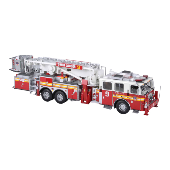
FIRE TRUCK
TOWER LADDER 9
Pack 02
B U I L D
I N S T R U C T I O N S
STAGE 09: FRONT RIGHT WHEEL & LADDER
NAME PLATE
STAGE 13: COMPONENTS FOR THE CAB
CENTRAL CONSOLE
STAGE 10: COMPONENTS FOR THE CAB ROOF
AND FRONT WHEELS
STAGE 14: REAR RIGHT CAB DOOR &
CAPTAIN'S SEAT
STAGE 11: LEFT-HAND SIDE LIGHTBAR &
COMPONENTS FOR THE CHASSIS
STAGE 15: CAB FLOOR AND ENGINEER' S SEAT
STAGE 12: COMPONENTS FOR THE FRONT
STAGE 16: COMPONENTS FOR THE MOBILE
BUMPER & FRONT RIGHT STABILIZER
DATA TERMINAL , WING MIRRORS , CAB INSIDE
ROOF & DOME LIGHTS
STAGE 12B: MAIN CHASSIS , DOOR STEPS &
WHEEL ARCHES
Advertisement

Related Manuals for Agora Models FDNY FIRE TRUCK TOWER LADDER 9


Summary of Contents for Agora Models FDNY FIRE TRUCK TOWER LADDER 9
- Page 1 FIRE TRUCK TOWER LADDER 9 Pack 02 B U I L D I N S T R U C T I O N S STAGE 09: FRONT RIGHT WHEEL & LADDER NAME PLATE STAGE 13: COMPONENTS FOR THE CAB CENTRAL CONSOLE STAGE 10: COMPONENTS FOR THE CAB ROOF AND FRONT WHEELS STAGE 14: REAR RIGHT CAB DOOR &...
- Page 2 Advice from the experts Please keep ALL unused screws as they will be required in a later stage. Please make sure you don’t mix up the screws. They look quite similar, but the threads do vary slightly. Using the wrong screws may damage the parts. When securing parts together using multiple screws, fit each screw loosely to ensure all the parts are correctly aligned before gently tightening them firmly, but not overtight, in the order in which you placed them.
- Page 3 Stage 09: Front Right Wheel & Ladder Name Plate In this first stage of pack 2, you will assemble the front right wheel. S T A G E 0 9 P A R T S L I S T Name Ladder name plate Front tire Wheel...
- Page 4 Stage 09: Front Right Wheel & Ladder Name Plate S T E P 1 The tire fits onto the wheel in the same way as the tires in stage 01. If Carefully remove the tire with tweezers and shake off the excess water. the tire won’t stretch, soak it in a hot water bath for two minutes.
- Page 5 Stage 09: Front Right Wheel & Ladder Name Plate S T A G E C O M P L E T E AGORAMODELS FDNY FIRE TRUCK...
- Page 6 Stage 10: Components for the Cab Roof and Front Wheels You’ll now add more components to the cab roof before assembling the front wheel axle and wheel hubs and attaching the front right wheel. S T A G E 1 0 P A R T S L I S T Name Front axle Track rod...
- Page 7 Stage 10: Components for the Cab Roof and Front Wheels S T E P 1 ASSEMBLING THE CONDENSER Carefully lay the condenser grille on the ledge. Take the condenser grille frame and apply a lttle superglue around the ledge of the frame. The grille should sit on the condenser like this.
- Page 8 Stage 10: Components for the Cab Roof and Front Wheels The condenser grille has now been fitted in place. Push the two pegs on the underside of the condenser assembly into the corresponding holes in the cab roof. Note: the pegs and holes are different sizes to determine the correct fit.
- Page 9 Stage 10: Components for the Cab Roof and Front Wheels S T E P 2 ASSEMBLING THE WHEEL HUBS, TRACK ROD AND FRONT RIGHT WHEEL Take the right wheel hub and lower it onto this post of the main front axle.
- Page 10 Stage 10: Components for the Cab Roof and Front Wheels Now take the track rod and rest it on the main axle, just behind the Repeat on the opposite side, lifting the right wheel hub and hooking it wheel hubs. Lift up the left wheel hub and hook the projecting hole over the pin on the other end of the track rod.
- Page 11 Stage 10: Components for the Cab Roof and Front Wheels Align the front right wheel from stage 9 with the right wheel hub. Push the wheel firmly onto the hub. Secure the wheel in place using 1 x screw type L from stage 6. Keep Drop the two coil springs onto the axle post or keep them safe until the 2 x type L screws supplied with this stage for use in stage 12B.
- Page 12 Stage 10: Components for the Cab Roof and Front Wheels S T A G E C O M P L E T E AGORAMODELS FDNY FIRE TRUCK...
- Page 13 Stage 11: Left-hand Side Lightbar & Components for the Chassis In this next stage, you’ll fix the left- hand side lightbar to the roof, and unpack components that will be attached to the chassis supplied in the next stage. S T A G E 1 1 P A R T S L I S T Name Cylinder Crossmember...
- Page 14 Stage 11: Left-hand Side LightBar & Components for the Chassis S T E P 1 Fit the lightbar to the cab roof by feeding the cable through the The left-hand lightbar has now been fitted. opening in the roof before pushing the mounting firmly into place. S T A G E C O M P L E T E AGORAMODELS FDNY FIRE TRUCK...
- Page 15 Stage 12: Components for the Front Bumper & Front Right Stabilizer In stage 12, you’ll continue to work on the front bumper, adding the bell, tow hooks and front right stabilizer. S T A G E 1 2 P A R T S L I S T Name Front right stabilizer Front bumper plating...
- Page 16 Stage 12: Components for the Front Bumper & Front Right Stabilizer S T E P 1 Align the front bumper plating with the front bumper that was Push the three pins firmly into the corresponding holes to fit. assembled in stage 04. Next, assemble the bell.
- Page 17 Stage 12: Components for the Front Bumper & Front Right Stabilizer Align the two pins on the bell support with the two small holes in the The fire truck bell is fitted firmly in place. centre of the bumper plating. Push the pins into the holes. If the fit is tight, try filing off a little excess paint from the pins (inset).
- Page 18 Stage 12: Components for the Front Bumper & Front Right Stabilizer Both tow hooks have been fitted to the front bumper. With the reverse side of the bumper facing you, align the bracket on the stabilizer with the hole and peg inside the bumper. Fit the bracket over the hole and peg.
- Page 19 Stage 12: Components for the Front Bumper & Front Right Stabilizer S T A G E C O M P L E T E AGORAMODELS FDNY FIRE TRUCK...
- Page 20 Stage 12B: Main chassis, Door Steps & Wheel Arches Now you have the main chassis, you’ll start to fix components to it, including the steps and wheel arches supplied in this stage. Note: the chassis components listed below come in a separate box to the rest of the parts in pack 2.
- Page 21 Stage 12B: Main chassis, Door Steps & Wheel Arches S T E P 1 Rest the main chassis upside down on your work surface, and take the Push the chassis front part B firmly to fit. chassis front part B from stage 11. Align the peg on the chassis part with the hole at the front end of the main chassis, and push into place.
- Page 22 Stage 12B: Main chassis, Door Steps & Wheel Arches Turn the main chassis over again to secure chassis part A in place This is how the chassis front part A should look once fixed in the correct position. using a type H screw. S T E P 2 Bigger hole Smaller hole...
- Page 23 Stage 12B: Main chassis, Door Steps & Wheel Arches Smaller Smaller Bigger Bigger Push the pegs on the step into the corresponding holes on the right- Next, take the right-hand rear cab door step (again, the different sized pegs determine the correct placement) and apply a little glue to the hand side of the chassis.
- Page 24 Stage 12B: Main chassis, Door Steps & Wheel Arches ... followed by the left-hand rear cab-door step... Repeat to fix the outrigger pad to the left-hand side of the chassis..and the left-hand front cab-door step. AGORAMODELS FDNY FIRE TRUCK...
- Page 25 Stage 12B: Main chassis, Door Steps & Wheel Arches S T E P 3 Now the steps are in place, the wheel arches can be assembled. Start Align the four holes with the four pins on the chassis. by test-fitting the wheel arches on the left-hand side of the main chassis before gluing the flange that rests on the chassis.
- Page 26 Stage 12B: Main chassis, Door Steps & Wheel Arches Align the arch on the right-hand side of the chassis..and press firmly into place. The process is similar to fix the chrome-finish wheel arch surrounds Align the four holes and pegs, and then press firmly to fit into place on to the front of the chassis.
- Page 27 Stage 12B: Main chassis, Door Steps & Wheel Arches Repeat to fix the wheel arch surround on the left-hand side. Apply a ... align the four pegs and holes, and then press firmly into place. little glue to the flange... S T E P 4 ATTACHING THE DRIVESHAFT TO THE CHASSIS At the same time, push the front end of the driveshaft into chassis...
- Page 28 Stage 12B: Main chassis, Door Steps & Wheel Arches Push the driveshaft/axle assembly into position on the main chassis, Secure the driveshaft/axle assembly in place using 10 x type L screws. hold it in place, and turn the main chassis over to that you can see the Do not overtighten the screws here –...
- Page 29 Stage 12B: Main chassis, Door Steps & Wheel Arches Align the two pegs on the exhaust pipe from stage 11 with the two Push the pegs into the holes and press firmly to fit. holes on the underside of the main chassis. Secure the exhaust pipe in place from the upper side of the main chassis using a type H screw.
- Page 30 Stage 12B: Main chassis, Door Steps & Wheel Arches Take the cylinder from stage 11 and, working on the underside, align Press the cylinder firmly into position. the two pegs with the two holes on the main chassis as shown. Turn the chassis over and secure the cylinder in place using a type C screw.
- Page 31 Stage 12B: Main chassis, Door Steps & Wheel Arches Continuing on the underside, fit the connector from stage 11 onto the Push the connector firmly to fit into place. cylinder already in the central section of the main chassis. S T E P 5 MOUNTING THE FRONT AXLE TO THE MAIN CHASSIS Push the coil springs into the tubes on both sides.
- Page 32 Stage 12B: Main chassis, Door Steps & Wheel Arches Secure the front axle in place using 2 x type L screws supplied with stage 10. S T A G E C O M P L E T E Keep all the screws in a safe place. AGORAMODELS FDNY FIRE TRUCK...
- Page 33 Stage 13: Components for the Cab Central Console The cab will be the focus over the next few stages. You’ll start by assembling components onto the central console. S T A G E 1 3 P A R T S L I S T Name Central console Cab divider glass...
- Page 34 Stage 13: Components for the Cab Central Console S T E P 1 Align the speaker with the end of the central console as shown. Press into position, making sure that the red and black cables are routed through the two slots either side of the screw hole. Line up the two screw holes on the speaker cover with the two screw Fit the speaker cover in place.
- Page 35 Stage 13: Components for the Cab Central Console Secure the speaker cover with 2 x type C screws. The handles can now be fitted on either side of the console. Line up the two pins on the handle with the two tiny holes on the side of the central console.
- Page 36 Stage 13: Components for the Cab Central Console Both handles have now been fitted. Align the pin on the axe with the hole in the side of the console, below the left-hand handle. Push the axe firmly into position. Now take the cab divider glass and note that the two holes in the middle are different sizes.
- Page 37 Stage 13: Components for the Cab Central Console Aign the two pegs on the central console storage with the two holes Press the central console storage firmly to fit. on the divider glass (the size of the holes will ensure you have the correct orientation).
- Page 38 Stage 13: Components for the Cab Central Console Lastly in this stage, take the engineer’s switch panel and align the pin Press firmly to fit. on its bottom edge with the hole on the central console. S T A G E C O M P L E T E AGORAMODELS FDNY FIRE TRUCK...
- Page 39 Stage 14: Rear Right Cab Door & Captain’s Seat Next you’ll assemble the rear-right cab door and the captain’s seat. S T A G E 1 4 P A R T S L I S T Name Inner cab panel Seat support Outer door panel Inner door panel...
- Page 40 Stage 14: Rear Right Cab Door & Captain’s Seat S T E P 1 Align the seat support with the captain’s seat so the raised screw hole Apply a little glue to the flat surface of the seat support. is facing you. Check that the screw hole is nearest the back of the seat, not the front.
- Page 41 Stage 14: Rear Right Cab Door & Captain’s Seat S T E P 2 ASSEMBLING THE REAR-RIGHT CAB DOOR Push the handle into the hole in the inner door panel. Press firmly until you feel it click into place. Check that you have the gear the correct way up – the flatest side faces up.
- Page 42 Stage 14: Rear Right Cab Door & Captain’s Seat Apply a drop of superglue to each of the three Align the three peg holes on the inner door peg holes as indicated (circled). panel with the three pegs of the inner side of the outer door panel before pressing the parts firmly together.
- Page 43 Stage 14: Rear Right Cab Door & Captain’s Seat Apply a drop of superglue to the recess for the door handle. Press the handle into position. This is a D-shaped fitting to ensure the correct fit. The handle has now been fitted. AGORAMODELS FDNY FIRE TRUCK...
- Page 44 Stage 14: Rear Right Cab Door & Captain’s Seat S T A G E C O M P L E T E AGORAMODELS FDNY FIRE TRUCK...
- Page 45 Stage 15: Cab Floor and Engineer’s seat The cab will start to take shape in this next stage as you combine the central console with the cab floor, install the engineer’s and captain’s seats, and add more all-important rescue equipment. Note how all seats, except the engineer’s seat, have air packs located in the back of the seat so all fire fighters have to...
- Page 46 Stage 15: Cab floor and Engineer’s seat S T E P 1 Place the cab floor on your work surface and align the underside of the The centre console has been fitted to the cab floor. centre concole over the top, making sure not to trap the speaker cable. The two posts at the ends of the console will fit into the raised screw sockets on the floor as shown.
- Page 47 Stage 15: Cab floor and Engineer’s seat Push the seat firmly onto the support. The engineer’s seat can now be fitted to the cab floor. Align the pegs under the support with the raised holes on the floor (arrows). The seat support is angled at the back to match the shape of the floor. Secure the engineer’s seat in place from the underside using a type H screw from stage 13.
- Page 48 Stage 15: Cab floor and Engineer’s seat The support for the captain’s seat already forms part of the floor. Take Press the seat firmly in place. the captain’s seat from stage 14 and align the tabs and screw socket on the bottom of the seat as shown. Secure the captain’s seat from the underside using another type H Align the peg on the thermal imaging camera with the hole in the screw from stage 13.
- Page 49 Stage 15: Cab floor and Engineer’s seat Press firmly to fit into place as shown. Align the two pins on the halligan bar with the two small holes in the floor, next to the thermal imaging camera. Push firmly to fit into place. The tools stored in the jumpseat area on the right-hand side have Check that the tools have been firmly fitted into place by looking at been installed.
- Page 50 Stage 15: Cab floor and Engineer’s seat Now the magnets will be fitted to the floor. Note that each magnet The red line is visible in each recess in the four corners of the has a red line on one side. The line corresponds to the red line in the underside of the floor.
- Page 51 Stage 15: Cab floor and Engineer’s seat The remaining three magnets are fixed in the same way in the Place a magnet in the recess with the red line on the magnet facing the red line in the recess. remaining three recesses. In this picture, all four magnets have been glued in place.
- Page 52 Stage 16: Components for the Mobile Data Terminal, Wing Mirrors, Cab Inside Roof & Dome Lights In this final stage of pack 2, you’ll assemble and install the mobile data terminal (MDT) and add dome lights to the interior cab roof. S T A G E 1 6 P A R T S L I S T Name Cab inside roof...
- Page 53 Stage 16: Components for the Mobile Data Terminal, Wing Mirrors, Cab Inside Roof & Dome Lights S T E P 1 Start by applying a little glue to the base of the MDT frame. Align the pegs on the underside of the keyboard with the two holes on the frame.
- Page 54 Stage 16: Components for the Mobile Data Terminal, Wing Mirrors, Cab Inside Roof & Dome Lights Check that the screen is positioned with the curved side facing up The MDT has been assembled and is ready to be fitted to the cab. before pressing it onto the frame.
- Page 55 Stage 16: Components for the Mobile Data Terminal, Wing Mirrors, Cab Inside Roof & Dome Lights Place the cab inside roof on your work surface, flat side facing down. If necessary, apply a little PVA glue to the back of each light to hold Place the dome lights in the two circular recesses as shown.
- Page 56 Stage 16: Components for the Mobile Data Terminal, Wing Mirrors, Cab Inside Roof & Dome Lights S T A G E C O M P L E T E AGORAMODELS FDNY FIRE TRUCK...
Need help?
Do you have a question about the FDNY FIRE TRUCK TOWER LADDER 9 and is the answer not in the manual?
Questions and answers