Table of Contents
Advertisement
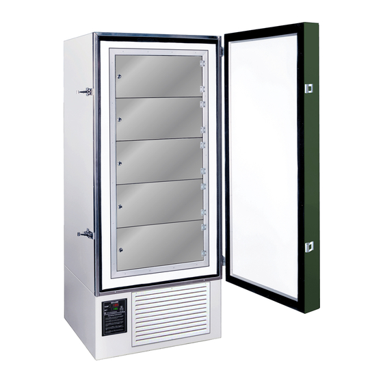
U85 / C85 / PH85 / PV85 SERIES
WARNING: READ BEFORE CONTINUING
To reduce the risk of fire, electric shock or injury to persons using this freezer, read all
instructions and follow basic safety precautions before using the unit, including the following:
Do not modify the plug provided with the freezer. If it will not fit the outlet,
have a proper outlet installed by a qualified electrician.
Do not position equipment so it is difficult to disconnect from the power supply.
freezer must be at least 6" away from any wall or object on any side.
While under warranty, do not attempt to repair or replace any part of the
freezer for servicing without first contacting the So-Low Service Department.
SAVE THESE INSTRUCTIONS
So-Low Environmental Equipment Company
10310 Spartan Drive
Cincinnati, OH 45215-1221
Tel: 513-772-9410
http://www.so-low.com
ULTRA LOW FREEZER
INSTRUCTIONS
USER MANUAL
For customer service:
Email: sales@so-low.com
For parts replacement:
Email: parts@so-low.com
For technical support:
Email: service@so-low.com
CONTENTS
Advertisement
Table of Contents

Related Manuals for SO-LOW PV85 Series

Summary of Contents for SO-LOW PV85 Series
- Page 1 6” away from any wall or object on any side. While under warranty, do not attempt to repair or replace any part of the freezer for servicing without first contacting the So-Low Service Department. SAVE THESE INSTRUCTIONS...
- Page 2 ♦ SYMBOLS AND STARTING INSTRUCTIONS……………………….. ● MEANING OF ILLUSTRATED SYMBOLS…………………………………... ● STARTING INSTRUCTIONS………………………………………………….. ♦ UNIT REQUIREMENTS…………………………………………………. ● PRE-INSTALLATION INFORMATION………………………………………... ♦ PREVENTATIVE MAINTENANCE…..…………………………………. ● FREEZER STORAGE PROCEDURE……………………………………..…. ● ALARM BATTERY REPLACEMENT…...…………………………………….. ● CLEANING PROCEDURE…………………………………………………….. ● DEFROSTING PROCEDURE…………………………………………………. ● CLEANING AIR CONDENSER………………………………………………... ♦...
- Page 3 MEANING OF ILLUSTRATED SYMBOLS ILLUSTRATED SYMBOLS Various symbols are used in this safety manual in order to use the unit without danger of injury and damage of the unit. Be sure that you understand the warnings and cautions in this manual before operating the unit. CAUTION BLACK WITH YELLOW BACKGROUND LIGHTNING BOLT...
-
Page 4: Preventative Maintenance
PRE-INSTALLATION INFORMATION RANGE OF ENVIRONMENTAL CONDITIONS FOR WHICH THIS EQUIPMENT IS DESIGNED Indoor use. Altitude up to 2000m. Ambient temperatures 15°C to 30°C ( 60°F TO 85°F ) Recommended humidity range of 30% to 90%. Mains supply fluctuations up to -5% to +10% of the nominal voltage. Transient over-voltages typically present on the mains supply (overvoltage category II). - Page 5 The unit can be turned off for storage by unplugging the unit from the wall outlet and/or switching off the electrical breaker in the electrical box. ATTENTION RISK OF ELECTRICAL SHOCK USE CAUTION NEAR ELECTRICAL CONNECTIONS Once the unit is unplugged, the freezer will go into “Power Failure” alarm. To disable the Power Failure alarm;...
-
Page 6: Cleaning Procedure
NOTICE THE LO-BAT (LOW BATTERY ALARM) IS NOT ABLE TO BE SILENCED OR DISABLED. TO REDUCE THE VOLUME OF THE ALARM UNTIL A REPLACEMENT CAN BE INSTALLED, A PIECE OF TAPE CAN BE PLACED OVER THE BUZZER HOLE ON THE CONTROL To reduce the risk of fire, electric shock or injury to persons using this freezer, read all instructions and follow basic safety precautions. - Page 7 Wipe down the exterior of the freezer with a soft cloth and/or general spray type polish. Do not use corrosive cleaners/chemicals on the exterior. If frost builds up in the chamber, a bucket and ice-scraper can be used to remove ice. If excessive ice builds up, the unit can be defrosted (see below). DEFROST PROCEDURE 1.
-
Page 8: Unit Operation
Large amounts of dust build-up on the air-cooled condenser can cause excess stress for the refrigeration system. This excess stress may increase the chance of a refrigeration issue and reduce the life expectancy of the refrigeration system. ATTENTION IT IS RECOMMENDED TO CLEAN THE CONDENSER AT LEAST ONCE EVERY 90 DAYS TO PREVENT DUST BUILDUP. -
Page 9: Alarm / Relay Operation
The temperature control is manually adjustable to the desired temperature in 1° C increments within the limits of the control range. TEMPERATURE SET POINT The control has two displays; 1) The upper display ( TEMP ) is the current actual unit temperature. 2) The lower display ( SET ) is the temperature set point. -
Page 10: Control Programming
When operating the unit for the first time, the alarm will be disabled until the unit reaches set point, or 8 hours after the unit has been first plugged in. The alarm will not sound again until the unit goes out of temperature range. ±... - Page 11 The FDC-4000 controller is programmed by using three keys on the front panel. The available key functions are listed in following table. Note: Only use the tip of your finger to depress the keys. Using a rigid object such as a pen, screwdriver or even your finger-nail may permanently damage the keypad.
- Page 12 : Confused Character The upper display is used to show the process value or menu prompt. The lower display is used to show the set-point value or menu value. Both displays are blank while on battery power unless the button is pressed to display the process value.
-
Page 13: Calibration Procedure
To enter the PROGRAM parameter mode, hold the scroll key until the screen changes to ‘SPL’, then release. This will take approximately 15 seconds. To page through Parameters; Press and Release the scroll key Please read the superscript instructions (bottom of page) for each Parameter value. -
Page 14: Common Questions
To calibrate the control, the calibration parameter must be turned on. To enter the CALIBRATION mode, hold the scroll key until the screen changes to ‘SPL’, then release. This will take approximately 15 seconds. Press and Release the scroll key to page through Parameters. Once value SHF is shown, Use the or arrow keys to change value to ON. - Page 15 Q: When should I defrost my unit? A: Units should be defrosted when ice accumulation reaches approximately 1/2 inch thick. Ice acts like an insulator and has to work harder to reach the same temperature. Q: Is this unit self-defrosting? A: No, this unit is a manual defrost unit.
-
Page 16: Technical Assistance
EMBRACO FFI12HBX 50/60 FF12-115 DANFOSS SC15FTX 50/60 SC15-115 DANFOSS SC18FTX 208/220/230 50/60 SC15-208 TEMPERATURE CONTROL PARTS PART # FDC 4000 4000 FDC nCOMPASS nCOMPASS CASCADE ELECTRICAL PARTS PART # Heater Harness No. H-200 217-VOLTAGE Refrigeration Switch No. 2X464 TOGGLE Condenser Fan Motor No. GE-5411 - 115/60/1 500-115 Condenser Fan Motor No. - Page 17 IF FAILURE OCCURS AND UNIT IS STILL UNDER WARRANTY, DO NOT ATTEMPT TO MAKE ANY REPAIR MODIFICATIONS TO THE UNIT BEFORE CONTACTING THE SO-LOW SERVICE DEPARTMENT, AS THIS MAY RESULT IN WARRANTY BEING VOIDED. ◆ Model Number of Product < CHECK FOLLOWING ITEMS BEFORE CALLING OR EMAILING >...
-
Page 18: Technical Support
TECHNICAL SUPPORT MAINTENANCE CHECKLIST IT IS RECOMMENDED TO COMPLETE CHECKLIST EVERY 30 DAYS ◆ MODEL NUMBER OF PRODUCT ◆ SERIAL NUMBER OF PRODUCT ________________________________ ________________________________ Checked that freezer is operating at the correct setpoint temperature. Checked operation of condenser fans, and cleaned air cooled condenser. Confirmed unit is at least 6 inches away from walls, or obstacles, on all sides to allow for sufficient air flow.
Need help?
Do you have a question about the PV85 Series and is the answer not in the manual?
Questions and answers