Table of Contents
Advertisement
Quick Links
WS0832Professional Weather Station
1. Introduction
Thank you for your purchase of the
following user guide provides step by step instructions for installation, operation and
troubleshooting.
2. Warnings
Warning: Any metal object may attract a lightning strike, including your weather
station mounting pole. Never install the weather station during a storm.
Warning: Installing your weather station in an elevated location may result in injury or
death. Safety goes first. Make sure your setup and preparation is secure, and take no risks.
3. Getting Started
The WS0832 weather station consists of a display console (receiver), a sensor array
with Integrated Outdoor Transmitter and mounting hardware.
Parts List
The WS0832 weather station consists of the following parts (as referenced in Figure 1 ).
QTY
Display Console
Frame Dimensions (LxHxW):
1
135X26X96mm
LCD Dimensions (LxW): 111 x 75mm
Integrated Outdoor Transmitter
1
Dimensions (LxHxW):
330x150x280mm
Foot Mounting (with pole insert)
1
Dimensions: 84x 152 x 216mm
WS0832Professional Wireless Weather
Item
1
User Manual
station. The
Image
Advertisement
Table of Contents

Related Manuals for Sharper Image WS0832


Summary of Contents for Sharper Image WS0832
- Page 1 The WS0832 weather station consists of a display console (receiver), a sensor array with Integrated Outdoor Transmitter and mounting hardware. Parts List The WS0832 weather station consists of the following parts (as referenced in Figure 1 ). Item Image Display Console...
- Page 2 Item Image Mounting Bracket Back Plate (pole mount) Dimensions: 76 x 102 x 38mm Mounting Pole Dimensions: 76 x 76 x 25mm Pole mounting nuts (M3) / bolts Ø3) Pole mounting nuts (M5) / bolts ( Ø5) Tapping screws Manual Power Adapter...
-
Page 3: Recommended Tools
Figure 1 3.2 Recommended Tools ● Precision screwdriver (for small Phillips screws) ● Compass or GPS (for wind direction calibration) ● Adjustable Wrench ● Hammer and nail for hanging remote thermo-hygrometer transmitter. 3.3 Setup of Sensor The following illustration shows the full segment for Thermo-Hygrometer,WIND,RAIN and UV INDEX sensor. - Page 4 Figure 3 Remove the battery cover on the back of the sensor by removing the set screw, as shown in Figure 4. Figure 4 Inserting 3xAA batteries in the battery compartment, as show in Figure 5.
- Page 5 Figure 5 Close the battery cover. Make sure the gasket (around the battery compartment) is properly seated in its place prior to closing the door. Tighten the set screw. Note: Do not install the batteries backwards. You can permanently damage the sensors. The solar panel does not charge the batteries, so rechargeable batteries are not needed or recommended.
-
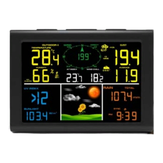
Page 6: Display Console Set Up
Figure 6 3.4 Display Console 3.4.1 Display Console Layout The display console layout is shown in Figure 7 Note: The following illustration shows the full segment LCD display for description purposes only and will not appear like this during normal operation. Figure 7 1. Out/Indoor temperature display 14.Time , date and year 2. - Page 7 It is r recomme ended to plug in t the powe er supply y to reduc ce the ba attery consu umption and exte end the se ervice lif ote: The sens sor array mus t be powered d and updating g before pow wering up the c console, or th...
- Page 8 Figure 12 1: Fold out the desk stand and see DC jack on the left ; as shown in Figure 13 Figure 13 2: Insert the DC plug correctly ; as shown in Figure 14 Figure 14 3: If you want to put it on a table or cabinet, opened the desk stand and turn the DC plug up until 90 degrees;...
-
Page 9: Sensor Operation Verification
Figure 15 4: If you want to hang on the wall, turn the DC plug down until 0 degrees and closed the desk stand; as shown in Figure 16 Figure 16 Note: If the power adapter is not plugged in, the icon will display . -
Page 10: Weather Station Installation
4.Weather Station Installation Pre Installation Check. Before installing your weather station in the permanent location, we recommend operating the weather station for one week in a temporary location with easy access. This will allow you to check out all of the functions, insure proper operation, and familiarize you with the weather station and calibration procedures. - Page 11 Brick 10-40% Concrete 40-80% Metal 90-100% 5.Final Installation of Sensors Integrated outdoor transmitter installation. Professional Wireless Weather Station can be used in both the Northern and Southern Hemispheres. Prior to installation, you will need to calibrate the wind direction. 5.1. Northern Hemispheres (NOR). The cardinal directions (N, S, E, W) molded on the body of the outdoor sensor are indicators for the Northern Hemisphere only.
- Page 12 Southern Hemispheres Figure 13 5.2. Southern Hemispheres (SOU). For Southern Hemisphere installations, ignore these(N, S, E, W) and face the solar panel to the North (and in a sunny position) when installing the Integrated outdoor transmitter. Step 1: Install the Integrated outdoor transmitter and face the solar panel North. Step 2: Console operation is set to Southern Hemispheres ( SOU in the time area) in Location division.
- Page 13 Figure 14 Tighten the mounting pole to your existing mounting pole with the four¢5 Bolts and M5 Nuts assembly, or fix on the wall with four tapping screw, as shown in Figure15.
-
Page 14: Low Battery Icon
Figure 15 6.Low Battery Icon A low battery indicator icon is shown in the display window for Integrated outdoor transmitter. When the low battery icon appears (the battery voltage is lower than 3.6V), replace the batteries in the sensor with fresh batteries. Be sure to never mix old and new batteries, and never mix battery types such as alkaline and lithium together. -
Page 15: Set (Program) Mode
1.Time, Date and Year. Press the CHANNEL/+ or MIN/MAX/- key to toggle between time, date and year. 2.Indoor Temperature. Press the CHANNEL/+ or MIN/MAX/- key to toggle between out/indoor for temperature and humidity alarm on/off view 3.Rainfall. Press the CHANNEL/+ or MIN/MAX/- key to toggle between rate, 24h, week, month and total. -
Page 16: Sensor Search Mode
12. Pressure Threshold Setting (default level 2). Press the SET(MODE) key again to change the pressure threshold. Press the [+] key or [-] key to change pressure threshold 2 mbar/hour to 4 mbar/hour.(For detailed information of this part please refer to 9.5) 13. -
Page 17: Back Light Mode
Note: If plugged into AC power, the backlight will remain on. It is not recommended leaving the backlight on for a long period of time when operating on batteries only, or the batteries will run down quickly. 8.Alarm Mode The WS0832 includes the following alarms: • Time • Out Temperature •... -
Page 18: Setting The Alarms
Press ALARM key again to view the LOW alarms along with the alarm clock time the same way HI alarms. Press the SNOOZE key at any time to return to the normal mode. 8.3 Setting the Alarms Press ALARM key to enter the alarm mode. Press and hold the SET key for three seconds. -
Page 19: Other Console Features
Note: To prevent repetitive alarming of humidity, there is a 4% tolerance band in humidity alarm. For example, if you set the high alarm to 60% and silence the alarm, the alarm icon will continue to flash until the humidity falls below 56%, at which point, the alarm will reset and must increase above 60% to activate again. - Page 20 9.4 Feels Like Temperature and AT Feels like temperature is a combination of Heat Index and Wind Chill. At temperatures less than 4.4C(40°F), the wind chill is displayed, as shown in the National Weather Service Wind Chill Table below: Figure 17 At temperatures greater than 26.7C(80°F), the heat index is displayed, as shown in the National Weather Service Heat Index Table below: Figure 18 When the temperature is between 4.4C (40°F) and 26.7C (80°F), the OUT temperature is...
-
Page 21: Pressure Threshold Setting
The concept of apparent temperature (AT) is a linear regression that is not restricted, and is more appropriate to outside conditions because it includes wind. and was intended as an assessment of what exposed body surfaces feel like in cold, windy conditions Regression equations of this universal scale are formulated for indoors, outdoors in shade but exposed to wind, and outdoors exposed to wind and solar radiation. -
Page 22: Power Consumption
Measurement Range Accuracy Resolution Indoor Temperature 0 to 60 °C ± 1 °C 0.1 °C Outdoor Temperature -40 to 60 °C ± 1 °C 0.1 °C Indoor Humidity 10 to 99 % ± 5% (only guaranteed between 20 to 90%) Outdoor Humidity 10 to 99% ±... -
Page 23: Troubleshooting Guide
Figure 52 2. Replace the wind, rain and thermo-hygrometer transmitter batteries once every 1-2 years Troubleshooting Guide. Problem Solution Wireless remote not reporting in to If any of the sensor communication is lost, dashes (--.-) console. will be displayed on the screen. To reacquire the signal, press and hold the CHANNEL/+ button for 3 seconds, There are dashes (--.-) on the display and the remote search icon... - Page 24 Problem Solution Indoor and Outdoor Temperature do not Allow up to one hour for the sensors to stabilize due to agree signal filtering. The indoor and outdoor temperature sensors should agree within 2 °C (the sensor accuracy is ± 1 °C). Use the calibration feature to match the indoor and outdoor temperature to a known source.
Need help?
Do you have a question about the WS0832 and is the answer not in the manual?
Questions and answers