Table of Contents
Advertisement
Advertisement
Table of Contents
Troubleshooting

Related Manuals for Fluke 1521


Summary of Contents for Fluke 1521
- Page 1 Hart Scientific 1521 Handheld Thermometer Readout User’s Guide Rev. 571203 ENG...
- Page 2 Limited Warranty & Limitation of Liability Each product from Fluke's Hart Scientific Division ("Hart") is warranted to be free from defects in mate- rial and workmanship under normal use and service. The warranty period is one year for the Handheld Thermometer Readout.
-
Page 3: Table Of Contents
Unpacking ......11 Use Proper Care with the 1521 and Accessories ..11 Learn About the Features and Components . - Page 4 7 Display Functions......25 8 Communications Interface....37 9 Calibration .
- Page 5 11 Troubleshooting......47 11.1 An Error Message Is Displayed ....47 11.2 CE Comments .
- Page 6 International Electrical Symbols ..... 1 Front of the 1521 ......13 Top and Side View .
-
Page 7: Before You Start
Before You Start Symbols Used Table 1 lists the International Electrical Symbols. Some or all of these symbols may be used on the instrument or in this manual. Table 1 International Electrical Symbols Symbol Description AC (Alternating Current) AC-DC Battery CE Complies with European Union Directives Double Insulated Electric Shock... -
Page 8: Safety Information
1521 Handheld Thermometer Readout User’s Guide Symbol Safety Information Use this instrument only as specified in this manual. Otherwise, the protection provided by the instrument may be impaired. The following definitions apply to the terms “Warning” and “Caution”. “Warning” identifies conditions and actions that may pose hazards to the user. -
Page 9: Cautions
AC adapter. Refer repairs or replacement components to the manufacturer. The instrument and thermometer probes are sensitive and can be easily damaged. Always handle these devices with care. DO NOT allow them to be dropped, struck, stressed, or overheated. -
Page 10: Authorized Service Centers
1521 Handheld Thermometer Readout User’s Guide Probes are fragile devices which can be damaged by mechanical shock, overheating, and absorption of moisture or fluids in the wires or hub. Damage may not be visibly apparent but nevertheless can cause drift, in- stability, and loss of accuracy. - Page 11 Chao Yang District Beijing 100004, PRC CHINA Phone: +86-10-6-512-3436 Telefax: +86-10-6-512-3437 E-mail: xingye.han@fluke.com.cn Fluke South East Asia Pte Ltd. Fluke ASEAN Regional Office Service Center 60 Alexandra Terrace #03-16 The Comtech (Lobby D) 118502 SINGAPORE Phone: +65 6799-5588 Telefax: +65 6799-5588 E-mail: antng@singa.fluke.com...
-
Page 12: Introduction
PRTs and thermistors. The unique combination of features makes this instrument suitable for a wide vari- ety of applications in industry. Features and capabilities of the 1521 include the following: Measures with platinum resistance thermometers (PRTs) and thermistors Works with Hart’s special INFO-CON probe connector (which is partially... -
Page 13: Specifications And Environmental Conditions
Specifications and Environmental Conditions Specifications Resistance Range Resistance Accuracy, PRT, one year † Resistance Accuracy, thermistor, one year † Temperature Range Temperature Accuracy, PRT Temperature Accuracy, 2.25 k thermistor † Temperature Accuracy, 10 k thermistor † Temperature Accuracy, 100 k thermistor †... -
Page 14: Environmental Conditions
1521 Handheld Thermometer Readout User’s Guide Digital Filter Remote Communications Display Operating Temperature Range Power Safety Size Weight † Accuracy specifications apply from 15 to 35°C. Accuracy specifications over the entire absolute operating range are 1.5 times the stated values. Temperature accuracy does not include probe uncertainty or probe characterization errors. -
Page 15: Quick Start
If all items are not present, call an Authorized Service Center (see Section 1.3). Use Proper Care with the 1521 and Accessories First and most important is to understand the safety issues related to the 1521 and its accessories. Be aware that potential hazards exist due to high tempera- tures, high voltages, and battery chemicals. -
Page 16: Connect The Power Source
AC adapter, plug it into a wall outlet of the appropriate voltage and in- sert the DC plug into the DC power input of the 1521 (see Figure 2.) To use the battery pack it must first be fully charged using the AC adapter (see Section 6.1). -
Page 17: Parts And Controls
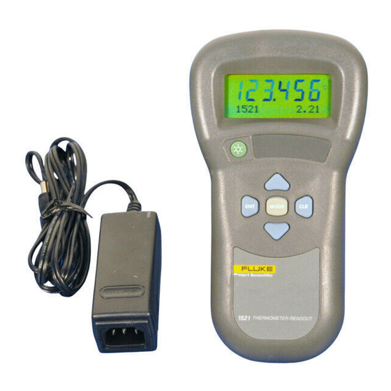
5 Parts and Controls Front Features Parts and Controls The functions of the various features of the 1521 are described below. Front Features The front of the 1521 features the LCD display and control buttons. - Page 18 1521 Handheld Thermometer Readout User’s Guide Display-The display shows the current temperature (or resistance) measure- ment on the large numeric upper portion of the display. It can also show a vari- ety of information on the smaller alphanumeric lower portion such as minimum, maximum, hold temperatures, delta(x), and other instrument settings.
-
Page 19: Top And Side Features
Serial Port Figure 2 Top and Side View The top and side of the 1521 feature the probe connector, DC power input, se- rial port, and infrared window. Probe Connector - At the top of the thermometer is the opening where the probe connector is inserted. -
Page 20: Back Features
Back Features See Figure 4 on page 19. Stand-The stand at the back of the 1521 can be flipped down to prop up the in- strument for better viewing. Battery Compartment- Behind the stand is the compartment that contains the battery pack. -
Page 21: Accessories
The 1521's accessories and their features are described here. AC Adapter-The AC adapter recharges the internal battery pack and can also be used to supply power to operate the 1521 while the battery is being charged (see Section 6.2). Serial Cable-The serial cable can be used to connect a computer or a printer to the 1521 through its serial port (see Section 8). - Page 22 This software can be used with your 1521 thermometer to collect and graph data. Carrying Cases - There are two types of cases available for your 1521 ther- mometer. The Model 9318 case is a hard case for carrying the thermometer and a 12"...
-
Page 23: General Operation
AC adapter (normally 115V, optionally 230V). Connect the DC plug of the adapter into the DC input of the 1521 located on the right side. The battery will be charged as necessary whether or not the instrument is switched... -
Page 24: Dc Power Source
The DC power source provides power to charge the battery. It can also be used to power the 1521 while the battery is being charged. The AC adapter provided with the 1521 is intended to be used for these purposes. Use only the AC... -
Page 25: Power Button
The DC power source plugs into the DC power input on the right side of the 1521. – Figure 5 12V DC Power Source Polarity WARNING: The AC adapter has circuits with high voltages inside that could present danger of electric shock or fire if exposed. -
Page 26: Probe
Probe The probe is used to sense temperature. The probe attaches to the 1521 using a Hart INFO-CON probe connector that plugs into the top of the instrument. The probe connector must be properly programmed with the correct charac- teristics of the probe for measurements to be accurate (see Section 6.6). -
Page 27: Info-Con Connector
Keep the probe wires clean and away from fluids. INFO-CON Connector The probe connects to the top of the 1521 using a Hart INFO-CON connector (see Figure 3 on page 17). The probe connector will fit snugly and lock into place when it is fully inserted. -
Page 28: Figure 6 Probe Wiring Diagrams
1521 Handheld Thermometer Readout User’s Guide ognize that accuracy may be significantly degraded using a two-wire connec- tion because of wire resistance. Four-wire Connection Figure 6 Probe Wiring Diagrams Three-wire Connection Short Two-wire Connection Short... -
Page 29: Display Functions
Display Functions The 1521 operates in any of several modes which determine what information is visible in the lower alphanumeric portion of the display. The MODE button changes the mode. This button can be pressed repeatedly until a desired mode is set. -
Page 30: Blank Mode
1521 Handheld Thermometer Readout User’s Guide Each of these operating modes is described in the sections that follow. Min/Max Mode Figure 7 Operating Modes Flowchart Blank Mode This mode is identified by “Blank” that temporarily appears on the display. Blank Mode... -
Page 31: Min/Max Mode
In this mode nothing appears on the alphanumeric portion of the display. Use this mode if you are only interested in the latest measurements and want to sim- plify the appearance of the display. The message “Prb cal expired”, “Mtr cal expired”, “Recharge Needed”, or “Probe is locked”... -
Page 32: Units
1521 Handheld Thermometer Readout User’s Guide Units This mode is identified by “Units: C/ /F/K/R” that appears on the display. This mode allows you to select the unit of measurement: C for degrees Celsius, for resistance in ohms, F for degrees Fahrenheit, K for Kelvin, and R for Rankine. -
Page 33: Cal Mode
Always check to insure that the param- eters have been written to the INFO-CON connector by disconnecting the probe or by turning the 1521 off and on. The calibration menu is entered by pressing and holding the MODE button for three seconds. -
Page 34: Mtr Due
CAL2 - Set the 400 to 500 k instrument calibration parameter The calibration functions are described in detail in the following subsections. 7.8.1 Mtr Due This function displays the date the 1521 is due for calibration. The date cannot be changed with this function. 7.8.2 Prb Due This function displays the date the probe is due for calibration. -
Page 35: Date
Prb Type This function specifies the type of probe and its characterization. It allows the 1521 to use the appropriate algorithm to calculate temperature from the mea- sured resistance of the probe. The functions that follow the probe conversion function for setting probe characterization coefficients depend on the selected probe type. -
Page 36: Its-90
1521 Handheld Thermometer Readout User’s Guide ITS-90 IEC751 YSI400 THERM Each of the conversion options is explained in the following sections along with their associated coefficients, if they have any. The probe type and associ- ated coefficients are stored in the INFO-CON probe connector. Use the Up and Down buttons to select the probe type and the ENT button to store and continue. -
Page 37: Iec751
A PRT was calibrated to ITS-90 and its calibration certificate states values for coefficients R(273.16K), a4, b4, a8, and b8. Set the 1521 coefficients to the certificate values as follows. 1521 Coefficients R(.01) Example 2: A PRT was calibrated to ITS-90 and its calibration certificate states values for coefficients R(273.16K), a5, and b5. -
Page 38: Ysi-400
“b2" coefficient should be set to 0. Consider the following examples. Example 1: A thermistor has coefficients for the equation ln(R) as a function of T given as a, b, c, and d. Set the 1521 coefficients to the certificate values as follows: 1521 Coefficients 100 100... -
Page 39: Probe Wires
Example 2: A thermistor has coefficients for the equation ln(R) as a function of T given as a, b, and c. Set the 1521 coefficients to the certificate values as follows: 1521 Coefficients 7.8.14 Probe Wires This function sets the number of connecting wires in the probe. The probe wires setting is stored in the INFO-CON connector. -
Page 40: Filter
7.8.19 MDue This function shows the date the 1521 is due for calibration and allows it to be set. The meter calibration due date is regularly checked against the present date and if the calibration has expired the user is alerted with the message “Mtr cal expired”. -
Page 41: Communications Interface
RS-232 serial port. RS-232 Connection The three-conductor jack for the serial port is located on the top of the 1521 near the probe connector. One serial cable is included with the 1521. Additional or longer cables, of three meters or less, can be constructed by following the wiring diagram shown in Figure 8. -
Page 42: Communication Command List
The serial port can be used to transmit measurements to a computer or printer. It can also be used to change settings of the 1521 from a computer or interface with software. A full list of commands follows in Section 8.2. -
Page 43: Calibration Commands
Read probe type p[robe] Response Response Example Format Example res=1 time ti: hh:mm:ss ti: 16:23:45 ti=08:15:0 *idn? <manufacturer>, 2.11 Hart, <model>, 1521, <serial number>, 95001, <firmware version> *ver ver.<model>, ver.1521, <firmware version> 2.11 Response Example Format *pas=12345 date da: yyyy-mm-dd *pas ps:9... - Page 44 1521 Handheld Thermometer Readout User’s Guide Description Command Set probe type p[robe]=IT[S-90]/ IE[C751]/ C[VD]/ Y[SI400]/ T[HR] Read ITS-90 R(.01) or CVD R0 r[0] Set ITS-90 R(.01) or CVD R0 r[0]=n Read ITS-90 coefficient a/b/c/d/a4/b4 Set ITS-90 coefficient a/b/c/d/a4/b4=n Read CVD coefficient...
- Page 45 Description Command n Numeric data supplied by user 9 Numeric data returned to user x Character data returned to user Response Example Format 8 Communications Interface Communication Command List Response Example Range...
-
Page 46: Calibration
Calibration The 1521 should be calibrated at regular intervals to ensure that it continues to measure with proper accuracy. Calibration should only be done by qualified, authorized personnel. Required Equipment The following items are required to test and calibrate the 1521: 0 four-wire resistor (short) 25 four-wire resistor, uncertainty within 20 ppm (±0.0005 ) - Page 47 1521 Handheld Thermometer Readout User’s Guide 4. Verify the accuracy at 0 , 4k , 10 k , 40 k , 100 k , and 500 k . 5. Set the meter calibration date to the present date (see Section 7.8.18).
-
Page 48: Maintenance
If the AC adapter becomes damaged, have it replaced immediately. Never disassemble the AC adapter or attempt to repair it. If the instrument is used in a manner not in accordance with the equip- ment design, the operation of the thermometer may be impaired or safety hazards may arise. -
Page 49: Troubleshooting
Troubleshooting In case you run into difficulty while operating the 1521, this section provides some suggestions that may help you solve the problem. Below are several situa- tions that may arise followed by possible causes of the problem and suggested actions you might take. -
Page 50: Emc Directive
Electrical interference. Intense radio-frequency radiation near the 1521 or the probe can induce noise into the measurement circuits re- sulting in erratic readings. Try eliminating the source of interference or moving the 1521 to a different location. -
Page 51: Troubleshooting
The instrument was designed specifically as a test and measuring device. Com- pliance to the EMC directive is through IEC 61326-1 Electrical equipment for measurement, control and laboratory use – EMC requirements (1998). As noted in the IEC 61326-1, the instrument can have varying configurations. The instrument was tested in a typical configuration with shielded, grounded probe and RS-232 cables.
Need help?
Do you have a question about the 1521 and is the answer not in the manual?
Questions and answers