
Related Manuals for NSK Bruel & Kjaer Vibro ds821 Series

Summary of Contents for NSK Bruel & Kjaer Vibro ds821 Series
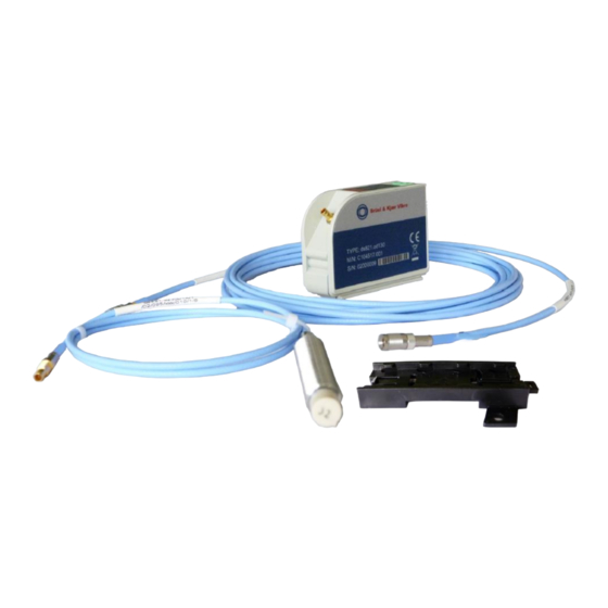
- Page 1 Instructions Displacement sensor system series ds821 Measuring range 4 mm Keep accessible for future reference...
- Page 2 Copyright © 2022 Brüel & Kjær Vibro GmbH All rights to this technical documentation remain reserved. Any corporeal or incorporeal reproduction or dissemination of this technical documentation or making this document available to the public without prior written approval from Brüel & Kjær Vibro GmbH shall be prohibited.
-
Page 3: Table Of Contents
Brüel & Kjær Vibro │Instructions Sensor ds821 4 mm Table of Contents Table of Contents Safety ........................5 Disclaimer .............................. 5 Intended usage ............................5 Limitations ............................. 6 General information ..........................6 User Qualification ..........................6 1.5.1 Recommendations to User ............................. 6 1.5.2 Prohibition of Unauthorized Modifications ...................... - Page 4 Functional check ....................19 Quick check ............................19 Troubleshooting ..........................19 Disassembly ......................21 Disconnecting the connecting plugs ....................21 Driver disassembly ..........................21 6.2.1 Disassembling driver with assembly adapter on hat-rail ..................21 6.2.2 Disassembling driver with assembly adapter, screw-mounted ................21 Replacing displacement sensor system components ..............
-
Page 5: Safety
Brüel & Kjær Vibro │Instructions Sensor ds821 4 mm Safety Safety NOTE! This manual is a part of the product. Read the manual carefully before using the product and keep it accessible for future use. CAUTION! This symbol warns of dangerous situations which can result from misuse of the product. NOTE! This symbol provides general and useful information for using the product. -
Page 6: Limitations
Hot surfaces • In line with the user manuals, sensors and cables can be operated in extensive ambient temperature ranges, whereby they can become hot through self-heating on housing walls and can produce burning. • When mounted at external heat or cold sources (e.g. machine parts), systems, sensors and cables can adopt dangerous temperatures, whereby burning, among other things, can occur in the event of contact. -
Page 7: Prohibition Of Unauthorized Modifications
Brüel & Kjær Vibro │Instructions Sensor ds821 4 mm Safety 1.5.2 Prohibition of Unauthorized Modifications System and accessories must not be changed neither in construction nor safety technology without the express consent of Brüel & Kjær Vibro. Any unauthorized modification excludes Brüel & Kjær Vibro's liability for resulting damages. - Page 8 Assembly of the sensor: CAUTION! The ceramic sensor tip is sensitive to shock. Transport and store the displacement sensor only with the included protective rubber cap. Always keep the protective rubber cap for later use. To avoid damage, make sure, especially during assembly and while operating the machine, that the sensor tip does not come into contact with other objects.
-
Page 9: Product Description
Brüel & Kjær Vibro │Instructions Sensor ds821 4 mm Product description Product description Observe the safety information in chapter "Safety"! Basic function The displacement sensor systems of the ds82x family are based on the non-contacting eddy current measurement process. The distance is measured between the tip of the displacement sensor and an electrically conductive surface and sent via a proportional voltage signal to a subsequent electronic monitor. -
Page 10: Nominal Overall Length Of The Displacement Sensor System
Nominal overall length of the displacement sensor system The nominal system length (N) refers to the length of the components displacement sensor (P) and extension cable (L). The optional extension cable is required whenever the length of the displacement sensor is 0.5 m or 1.0 m and with the help of the additional extension cable must be extended to the nominal system length of 5 m, 10 m or 25 m. -
Page 11: Delivery, Storage, Transport
Brüel & Kjær Vibro │Instructions Sensor ds821 4 mm Delivery, storage, transport Delivery, storage, transport Observe the safety information in chapter "Safety"! Delivery Check the packaging for damage upon delivery and make sure that the contents are complete. Components included in scope of supply: Complete Supplied Displacement... -
Page 12: Installation
Installation Read the safety information in the chapter "Safety" before installation. To assemble the displacement sensor system, proceed in the following order: • 4.1 Assembling the displacement sensor • 4.2 Assembling the driver (oscillator/demodulator) • 4.3 Connect the components together •... -
Page 13: Assembling The Displacement Sensor
Brüel & Kjær Vibro │Instructions Sensor ds821 4 mm Installation Assembling the displacement sensor 4.1.1 Displacement sensor for front-side mounting The front side-mountable displacement sensors are supplied with two nuts. You can use these nuts to lock it in place after adjustment (4.4 Setting up the measuring chain and the displacement sensor). Depending on the application, the sensor can be mounted forward-facing either within a machine or outside of a machine or through the machine housing. -
Page 14: Displacement Sensor For Rear-Side Mounting
4.1.2 Displacement sensor for rear-side mounting The sensor for rear-side mounting is assembled with the help of a sensor holder which preferably includes an integrated bulkhead receptacle. • Fix the displacement sensor using a retainer that is appropriate for the type of installation. We recommend using the holder AC-101/AC-3101. -
Page 15: Screw Mounting
Brüel & Kjær Vibro │Instructions Sensor ds821 4 mm Installation 4.2.2 Screw mounting NOTE! The screws for the installation are not included in the delivery contents. A suitable surface of at least 7x10 cm is required for screw mounting: • Solid metal: .... -
Page 16: Connect The Components Together
Connect the components together Connection options: • Connection via extension cable • Direct connection 4.3.1 Connecting and disconnecting plug connections The connector ends of the displacement sensor and the extension cable feature self-latching plug connections. They are plugged together, and not joined by a screw connection. To assemble, observe the following order: 1. -
Page 17: Setting Up The Measuring Chain And The Displacement Sensor
Brüel & Kjær Vibro │Instructions Sensor ds821 4 mm Installation Setting up the measuring chain and the displacement sensor The displacement sensor should be adjusted when the rotor is stationary. 4.4.1 Measurement set-up As a rule, a displacement measuring chain is adjusted with the help of a voltmeter and the "operating voltage". -
Page 18: Electrical Connection
Electrical connection Connect the driver with an electronic monitoring system (e.g. VC-6000) according to the drawing below.When setting up your measuring system you should observe the following behavior of the driver. The heating effect of the driver electronics During the warm-up phase the heating effect causes a drift in the static distance measurement. Displacement sensor Drift Operating time... -
Page 19: Functional Check
Brüel & Kjær Vibro │Instructions Sensor ds821 4 mm Functional check Functional check Observe the safety information in chapter Safety! Quick check After installing the displacement sensor system, you can check the measured values using a digital multimeter (Ri ≥ 100 kΩ). If the displacement sensor system is in correct operating condition, you will see the following values: Operating voltage Output signal U... - Page 20 Check the displacement sensor and the extension cable: • Measure the supply voltage I (terminal 2) with extension cable and displacement sensor connected. Disconnect the cable connected to the driver (terminal 1) and measure supply voltage I again. If I changes by about 1.8 mA, the sensor cable and the displacement sensor are OK.
-
Page 21: Disassembly
Brüel & Kjær Vibro │Instructions Sensor ds821 4 mm Disassembly Disassembly Observe the safety information in chapter Safety! Follow reverse order for disassembly: Disconnecting the connecting plugs see “Connection via extension cable” on page 16 Driver disassembly 6.2.1 Disassembling driver with assembly adapter on hat-rail 1. -
Page 22: Disposal
Disposal The driver is subject to the Waste Disposal Act for Electrical and Electronic Equipment. Do not dispose of the device in the regular household waste and observe local waste disposal regulations. WEEE Reg. No. DE 69572330 © Brüel & Kjær Vibro ● C104958.002 / V04 Page 22 of 32 Technical alterations reserved! -
Page 23: Technical Data
Brüel & Kjær Vibro │Instructions Sensor ds821 4 mm Technical data Technical data Observe the safety information in chapter "Safety"! For further technical specification we refer to our 4 mm series ds82x product specification BPS0135. The following typical characteristics are valid under the following conditions unless otherwise specified: +18 °C to +27 °C ambient temperature, -24 V DC supply voltage, 100 kΩ... -
Page 24: Dimensioning Of Assembly Adapter
Ambient conditions: Sensor Degree of protection for the tip acc. to IP68 / 2 h at 10 bar EN 60529 Pressure tightness (expected based on the design): Sensor tip 25 bar Sensor and corrugated tube protection 25 bar (valid only for ds3002) Driver Degree of protection for the driver acc. -
Page 25: Environmental Requirements
Brüel & Kjær Vibro │Instructions Sensor ds821 4 mm Technical data Environmental requirements 8.3.1 Reliability of the displacement sensor in different media CAUTION! Humidity or moisture inside the plug result in the displacement sensor system becoming defective. Seal the plug to prevent moisture from entering. If the displacement sensor system is used in other media such as water, it can have an impact on the measurement results. -
Page 26: Required Clearances And Minimum Distances For Displacement Sensors
8.3.3 Required clearances and minimum distances for displacement sensors Non-contacting eddy-current displacement sensors produce a high frequency electromagnetic field. If electrically conductive material other than the object to be measured is located inside this field, the measurement result will be distorted. When assembling your non-contacting displacement sensors, strictly observe the clearances and minimum distances illustrated in the following drawing. -
Page 27: Transfer Characteristics
Brüel & Kjær Vibro │Instructions Sensor ds821 4 mm Technical data Transfer characteristics The characteristic curves shown in the measurement report are created under the stated environmental conditions and with the stated target material. When you order a complete displacement sensor system, you will receive an individual measurement report which may deviate from the illustrated typical transfer function. -
Page 28: Measurement Report
Measurement report © Brüel & Kjær Vibro ● C104958.002 / V04 Page 28 of 32 Technical alterations reserved! -
Page 29: Declaration Of Conformity
Brüel & Kjær Vibro │Instructions Sensor ds821 4 mm Declaration of conformity Declaration of conformity © Brüel & Kjær Vibro ● C104958.002 / V04 ● Page 29 of 32 Technical alterations reserved! UNRESTRICTED DOCUMENT... -
Page 30: Simplified Diagram
Simplified diagram © Brüel & Kjær Vibro ● C104958.002 / V04 Page 30 of 32 Technical alterations reserved! - Page 31 Brüel & Kjær Vibro │Instructions Sensor ds821 4 mm Simplified diagram © Brüel & Kjær Vibro ● C104958.002 / V04 ● Page 31 of 32 Technical alterations reserved! UNRESTRICTED DOCUMENT...
- Page 32 Contact Brüel & Kjær Vibro GmbH Brüel & Kjær Vibro A/S BK Vibro America Inc Leydheckerstrasse 10 Lyngby Hovedgade 94, 5 sal 1100 Mark Circle 64293 Darmstadt 2800 Lyngby Gardnerville NV 89410 Germany Denmark Phone: +49 6151 428 0 Phone: +45 69 89 03 00 Phone: +1 (775) 552 3110...
Need help?
Do you have a question about the Bruel & Kjaer Vibro ds821 Series and is the answer not in the manual?
Questions and answers