Table of Contents
Advertisement
Quick Links
Product overview
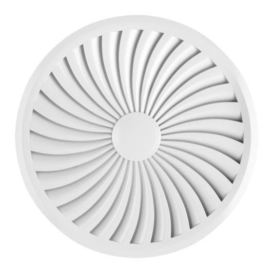
Fig. 1: Schematic illustration of the AIRNAMIC, with plenum box for horizontal duct connection
Diffuser face
①
Central fixing screw with decorative cap
②
Plenum box
③
Cross bar
④
Equalising element (Z: for supply air)
⑤
Installation manual
Air terminal devices
AIRNAMIC
Air terminal devices AIRNAMIC
GB/en
Suspension lug
⑥
Spigot
⑦
Double lip seal
⑧
Damper unit for volume flow rate balancing
⑨
TROX GmbH
Heinrich-Trox-Platz
47504 Neukirchen-Vluyn, Ger-
many
Germany
Phone: +49 (0) 2845 2020
+49 (0) 2845 202-265
E-mail: trox@trox.de
http://www.troxtechnik.com
1
Advertisement
Table of Contents

Related Manuals for Trox Technik AIRNAMIC Series


Summary of Contents for Trox Technik AIRNAMIC Series
- Page 1 Installation manual GB/en TROX GmbH Heinrich-Trox-Platz 47504 Neukirchen-Vluyn, Ger- many Germany Air terminal devices Phone: +49 (0) 2845 2020 +49 (0) 2845 202-265 E-mail: trox@trox.de AIRNAMIC http://www.troxtechnik.com Product overview Fig. 1: Schematic illustration of the AIRNAMIC, with plenum box for horizontal duct connection Diffuser face Suspension lug ①...
-
Page 2: Important Notes
Important notes Fig. 2: Schematic illustration of AIRNAMIC, nominal sizes 160 and 250, with spigot for connection to a ver- tical duct Diffuser face Spigot Bayonet fixing Screw fixing of the spigot Qualified staff Important notes Specialist personnel Information on the installation manual Specialist personnel are individuals who have suffi- cient professional or technical training, knowledge This manual enables operating or service personnel... -
Page 3: Transport And Storage
Transport and storage The actual scope of delivery may differ from the Correct use information in this manual for special constructions, Air terminal devices are used for the ventilation of additional order options or as a result of recent rooms in industrial and comfort areas. The air ter- technical changes. -
Page 4: Technical Data
Technical data Transport on site Technical data Dimensions and weight CAUTION! Danger of injury from sharp edges, sharp cor- ners and thin sheet metal parts! Sharp edges, sharp corners and thin sheet metal parts may cause cuts or grazes. – Be careful when carrying out any work. - Page 5 Technical data Fig. 4: AIRNAMIC-R with plenum box for horizontal duct connection Fig. 5: AIRNAMIC-R with plenum box for horizontal AIRNAMIC-R-*-H duct connection, nominal size 250 ØD1 H1 ØD3 H3 ØD ① 274 293 158 189 400L 362 290 198 166 400H 362 290 198 166 573 344 248 189...
-
Page 6: Installation
Installation ØD1 ØD2 Aeff m² R/400L 0.0186 R/400H 0.0258 R/600 0.0504 Installation General information Personnel: Specialist personnel Protective equipment: Industrial safety helmet Fig. 7: Diffuser face AIRNAMIC-Q Protective gloves Safety shoes AIRNAMIC-Q □Q₂ □Q₁ Aeff Installation notes: m²... - Page 7 Installation Ceiling diffusers It is recommended to suspend plenum boxes for Installation with plenum box ceiling diffusers before you put the ceiling tiles into place; if this is not possible, remove the adjacent ceiling tiles. Nominal sizes 160 and 250 can be installed at a later stage if the duct is already in place.
- Page 8 Installation Installation without plenum box, nominal sizes 160 and 250 Fig. 12: Flush ceiling installation with circular plenum box Duct À Suspension lug Á Fig. 14: Flush ceiling installation with spigot Diffuser face  Seal à Diffuser face À Spigot Á...
- Page 9 Installation Ceiling systems Fixing the diffuser face to the plenum box In order to protect the surface of the diffuser face, unpack and install it only after all other construc- tion steps have been completed. If there is a lengthy break between installation and commissioning, cover all openings of the casing (e.g.
- Page 10 Installation The central fixing screw for size 250 mm has to be inserted into a clamp in the plenum box Fig. 18: Installing the diffuser face Insert the central fixing screw (Fig. 18/3) on the back of the diffuser face (Fig. 18/2), then insert the diffuser face with the fixing screw into the plenum box (Fig.
- Page 11 Installation Diffuser face without plenum box Fig. 19: Bayonet fixing and fixing points 3 fixing points No tools required to fix the diffuser face, nominal sizes 160 and 250 Fig. 20: Installation of nominal sizes 160 and 250 Air terminal devices AIRNAMIC...
- Page 12 Installation Fig. 21: Installation of nominal sizes 160 and 250 Air terminal devices AIRNAMIC...
-
Page 13: Initial Commissioning, Maintenance And Cleaning
Initial commissioning, maintenance and cleaning Duct connection Initial commissioning, maintenance and cleaning The plenum box has a spigot for duct connection. Variants with a double lip seal allow for a sufficiently Initial commissioning tight connection; additional sealing is not required. Before you start commissioning: Check that the air terminal devices are cor- ... - Page 14 Initial commissioning, maintenance and cleaning Fig. 23: Damper blade closed (90°, only with plenum box) Damper unit or blade ① Sticker explaining the damper blade position ② ③ Setting lever Maintenance and cleaning Please note: The cleaning intervals given in the VDI 6022 ...
Need help?
Do you have a question about the AIRNAMIC Series and is the answer not in the manual?
Questions and answers