
Related Manuals for Espin NERO


Summary of Contents for Espin NERO
- Page 1 effortlessly electric Quick Start Guide CONTACT US: HELLO@ESPINBIKES.COM PHONE NUMBER : (888) 296-4550...
-
Page 2: Table Of Contents
Thank you for your purchase, and welcome to the Espin family! This guide will help you assemble, operate, maintain, and enjoy your Espin for as long as possible. For any questions or issues along the way, please reach out to us online or on the phone... -
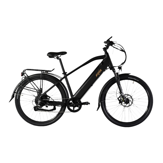
Page 3: Taking The Bike Out Of The Box
The bike shown above is the 21 Sport. Look through this diagram and find the labeled parts on hoses, or the zip-ties holding them in place. your own bike. Other Espin models might not have a top tube, have the battery in a different lo- 1 .6 Remove the metal or plastic dummy axle While removing the packaging on the bike, cation, or have a different type of stem. -
Page 4: Battery Removal, Installation, And Charging
BATTERY REMOVAL, INSTALLATION, AND CHARGING 2 .8 To install the battery, first make sure that it is unlocked. Then line up the teeth on the battery with the battery base, press it in as shown in Figure 3, then slide the bat- tery downwards onto the connector. -
Page 5: Install The Front Wheel
INSTALL THE FRONT WHEEL 3 .1 Unscrew the front axle nuts until they are 3 .4 The front axle assembly should now look flush with the end of the axle. Pull the axle like Figure 6. washer out against the nut as shown in Figure 4. -
Page 6: Install The Handlebar
The stem on some of our models may come pointing back- the stem with the Espin logo on the dis- wards to save space in the box. If the stem is play facing the rider. Put the faceplate... -
Page 7: Install The Pedals
• The Nero and Nesta come with 26” x 4.0” and 20” x 4.0” tires respectively. These might not in- clude a pressure range printed on the side, and instead just say 20PSI. We recommend 20PSI for paved surfaces, 15PSI for hard dirt trails, and 10PSI for snow, sand, or soft dirt/mud. -
Page 8: Install The Saddle And Adjust The Saddle Height
INSTALL THE SADDLE AND ADJUST FRONT FENDER, FRONT RACK, AND THE SADDLE HEIGHT FRONT LIGHT INSTALLATION 8 .1 Our bikes come with the front fender, front • Remove the packaging from the seatpost and saddle. light, and front rack removed for safer ship- ping. -
Page 9: Adjusting Stem Angle
• stem angle, first loosen the left side bolt on The Sport, Flow, Nero, and Nesta all come with the same type of suspension fork. It has a black the stem joint, as shown in Figure 28. The bolt lockout lever on the top of the right side, and a clear yellow cap labeled PRELOAD on the top of on the right does not need to be loosened. -
Page 10: How To Shift Gears And Operate The Pas
HOW TO SHIFT GEARS AND OPERATE THE PEDAL ASSIST SYSTEM (PAS) Figure 21 11 .4 The electrical controls are located on the 11 .8 Whether using the throttle or PAS, the left side of the handlebar, and are highlighted motor can be instantly shut off by squeezing in Figure 21. -
Page 11: Safety Checks
• adjusting bicycle derailleurs. Turn the power on. The Nero and Nesta will need the battery switched on before the display can be turned on. Test the throttle without any pedaling. Then, without using the throttle and while pedaling, test the Pedal Assist System starting with PAS 1, progressively moving to PAS 5. -
Page 12: Caring For Your Bike
Nero and Nesta. Leave the battery attached to 15 .4 The motor plug is underneath the non-drive side chain stay (refer to the bike diagram on maintain the water-tight seal over the connection. -
Page 13: Display Settings
DISPLAY SETTINGS 16 .1 You can access most of the settings programmed into the controller through the display and toggle switch. Some of these settings are welcome to be changed by the user, including P1, P2, P3, and A3. Most of the other parameters should not be changed from the settings recommended above, or else the bike might not function correctly or the circuitry could even get fried.
Need help?
Do you have a question about the NERO and is the answer not in the manual?
Questions and answers