Table of Contents
Advertisement
Advertisement
Table of Contents

Related Manuals for Delta DVP02LC-SL


Summary of Contents for Delta DVP02LC-SL
- Page 1 DVP02LC-SL Load Cell Module Operation Manual DVP-0071020-01...
-
Page 3: Table Of Contents
Product Profiles .........................5 Terminal Layout .........................6 LED Indicators...........................6 Installation and Wiring...........................6 Connecting DVP02LC-SL to DVP-SV series PLC MPU............6 Installing DVP02LC-SL and DVP-SV Series PLC MPU into DIN Rail ........7 Communication .........................7 External Wiring ..........................8 Functions of DVP02LC-SL ........................9 Control Registers (CR) ......................9 Explanations on Control Registers .................. - Page 4 Load Cell Module DVP02LC-SL Parameter Settings ......................... 23 Correction Settings ......................... 25 Status Settings........................26 Steps of Correction..........................28 Correction by MPU ......................... 28 Correction by Software ......................29 Application Examples ......................... 31 LED Indicators and Trouble-shooting ....................35 LED Indicators ........................35 Trouble-shooting........................
-
Page 5: Theory Of Load Cell
2. To ensure correct installation and operation of DVP02LC-SL, please read this operation manual carefully before using it. This operation manual only provides introductory information on DVP02LC-SL. For more detailed information on the theory of load cell, please refer to relevant references of literature. -
Page 6: Functions
Load Cell Module DVP02LC-SL Functions Rated power supply 24 VDC (-15 to +20%)/3 W voltage/power consumption Voltage boundary 18 to 31.2 VDC Max. current consumption 125 mA Input signal range ±40 mVDC Sensibility +5 VDC +/-10% Internal resolution 24 bits... -
Page 7: Product Profile And Outline
Load Cell Module DVP02LC-SL Example: If you use a load cell of eigenvalue 3.8 mV/V, please set CR#2 to “2” to acquire the best ENOB. When CR#3 is set to “2 ms”, the ENOB will be 19 bits. When CR#3 is set to “20 ms”, the ENOB will be 20.5 bits. -
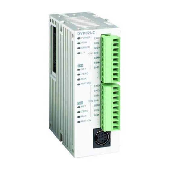
Page 8: Terminal Layout
Open the fixing clips on the top and bottom at the left side of DVP-SV series PLC MPU. Meet the connection ports alongside the 4 corners of DVP02LC-SL with DVP-SV, as step ① . Press the fixing clips on the top and bottom of the DVP-SV series PLC MPU and check if the connection is tight enough, as step ②... -
Page 9: Installing Dvp02Lc-Sl And Dvp-Sv Series Plc Mpu Into Din Rail
Installing DVP02LC-SL and DVP-SV Series PLC MPU into DIN Rail Use 35mm DIN rail. Open the DIN rail clips on DVP02LC-SL and DVP-SV series PLC MPU and insert them onto the DIN rail. Clip up the DIN rail clips to fix them on the rail. -
Page 10: External Wiring
DC/DC module System Conv ert er grounding A GND Grounding (100 or less) Many load cells connected in parallel connected to a single DVP02LC-SL: Load Cell Load Cell DVP02LC Load Cell Load Cell Load Cell Load Cell Load Cell Load Cell... -
Page 11: Functions Of Dvp02Lc-Sl
Set up by the system. H’1000 O Model name DVP02LC-SL model code = H’4206 H’1001 O Firmware version Displaying the current firmware version in hex. - Page 12 H’1028 O R/W zero weight status. zero point check Saving the present set value and writing all set values into the internal Flash for use next time when DVP02LC-SL is switched H’0: No action (Default) H’FFFF: Saving is successful Saving set value H’1029 X R/W...
-
Page 13: Explanations On Control Registers
The high byte is the ones digit, and the low byte is the tenths and hundredths digits, e.g. V1.01 = H’0101. CR#2: Eigenvalue Explanations: Since load cells of different brands own different specifications, please set up eigenvalues for DVP02LC-SL following the instructions and specification of the load cell you use. Value to be Specification Eigenvalue you need Note set in CR#2 0 <... - Page 14 Load Cell Module DVP02LC-SL Reaction time for measurement CR#3: Explanations: The reaction time refers to how long you sample once. The shorter the reaction time, the shorter the filtering time, bringing forth less stable measured values. However, the longest the reaction time, the most stable measured values you will acquire.
- Page 15 Load Cell Module DVP02LC-SL bit15 ~ 2 bit7 ~ 4 bit3 ~ 0 H’0 = gross weight Reserved H’1 = net weight H’F = channel disabled CR#8, 9: CH1 to CH2 tare weight Explanations: You can write in the weight or read it by commands. Default: K0. Range: K-32,768 to K32,767.
- Page 16 Load Cell Module DVP02LC-SL CR#22, 23, 24, 25: CH1 to CH2 unit of measurement Explanations: These control registers record the units of measurement in hex values corresponding to the ASCII words set up by the user. Each channel is able to contain maximum 4 ASCII words.
- Page 17 The present set value is saved, and all set values are written into the internal Flash for use next time when DVP02LC-SL is switched on. Default: 0. When H’5678 is written in, all set values will be saved in the Flash. When the saving is completed, CR#41 will become H’FFFF.
- Page 18 Load Cell Module DVP02LC-SL Status bit3 H’0008 CH2 exceeds max. weight (overload) bit4 H’0010 CH1 measured value is stable. bit5 H’0020 CH2 measured value is stable. bit6 ~ 15 Reserved CR#51: Error code Explanations: Content Error Content Error Power supply Hardware K1 (H’0001)
-
Page 19: Further Explanations On Each Function
Load Cell Module DVP02LC-SL Further Explanations on Each Function 5.3.1 Measure the Weight Normally, we can choose to measure the net weight or gross weight of an object. The net weight means the weight of the product itself, that is, the actual weight of the product without its external packaging. -
Page 20: Determining Zero Point
Load Cell Module DVP02LC-SL 100ms (10 × 10ms) and the range returns to be within 1,000, bit4 and bit5 of CR#50 will be set to 1 again. We recommend you check if the measured value is stable enough before controlling it. -
Page 21: Setting Up Dvp02Lc-Sl In Software
Setting up DVP02LC-SL in Software Initial Settings 1. Connect DVP02LC-SL to the PC. For how to connect, see 4.3. 2. Open the software for DVP02LC-SL. Select “Option” -> “Communication Setting”. 3. Set up the communication parameters according to the settings below. - Page 22 PC. Click “OK” to upload them and replace the set values already in the software. 6. Once you enter the online status, the screen will show the real-time data of DVP02LC-SL, including its current firmware version, the average values of CH1 and CH2, the average value of CH1 + CH2,...
-
Page 23: Communication Settings
“32767”. Once the filtering function is enabled, the average times have to be > 30, and the filter percentage has to be set. 7. In the connection, if you would like to upload the data in DVP02LC-SL to software, click the icon Or click the icon if you would like to download all the parameters set in the software to DVP02LC-SL. - Page 24 Load Cell Module DVP02LC-SL Characteristic Value/Measurement time Characteristic value: The eigenvalue, corresponding to the value set in CR#2. Scroll down to select 1, 2, 4 or 6 mV/V. The default setting is 2 mV/V. Measurement time: Corresponds to the value set in CR#3. Scroll down to select 2, 10, 20, 40 or 80 ms.
-
Page 25: Parameter Settings
When all the settings are done, click “download” to download the parameters to DVP02LC-SL, or click “Upload” to display the parameters of DVP02LC-SL in the software. DVP-PLC Operation Manual... - Page 26 Load Cell Module DVP02LC-SL Gross/Net: Corresponds to the value in CR#7. Scroll down to select displaying the gross weight or net weight. Tare weight: Corresponds to the value in CR#8 and CR#9. Enter the tare weight here, or click “Read TW” to set it up.
-
Page 27: Correction Settings
Parameters include reset to zero point commands, weight base point commands and weight correction commands for CH1 and CH2. When all the settings are done, click “download” to download the parameters to DVP02LC-SL, or click “Upload” to display the parameters of DVP02LC-SL in the software. -
Page 28: Status Settings
6.5 Status Settings In the status setting window, you can view the measuring results and the operation status of DVP02LC-SL, including the present average value in CH1 and CH2, the unit of measurement, status codes and error codes. Average value: The average weights at CH1 and CH2, corresponding to the values in CR#12 and CR#13. - Page 29 CH2 is stable, the indicator will turn red. Error Code: Corresponds to the value in CR#51, displaying the operation status of DVP02LC-SL, including power supply abnormality, hardware abnormality, SEN voltage errors and conversion errors. Power supply abnormality: Corresponds to bit0 of CR#51. When the power supply for DVP02LC-SL encounters abnormality, the indicator will turn red.
-
Page 30: Steps Of Correction
In this example, we connect DVP02LC-SL to a DVP series PLC MPU and correct CH1 by TO instruction. See 4.1 for how to connect DVP02LC-SL to the left side of the PLC MPU and supply power to the two devices. -
Page 31: Correction By Software
K100 7.2 Correction by Software In this example, we will demonstrate how to correct CH1 on DVP02LC-SL by the software. See 4.3 for how to wire the communication. Use a RS-232 communication wire to connect DVP02LC-SL to the PC and supply power to the two devices. - Page 32 Load Cell Module DVP02LC-SL Connect the load cell to CH1. See 4.4 for external wiring. DVP02LC-SL Load cell Open the software and see 6.1 for how to set up the connection between the software and DVP02LC-SL. Click “Parameters” on the left-hand side column to start setting up the parameters. Set up every parameter and eigenvalue according to the actual measuring requirements and specifications of the load cell.
-
Page 33: Application Examples
Application Examples Tension Control This is an example of using DVP02LC-SL in a tension control application. The main processing unit is DVP-SX2 series PLC (DVP20SX2), responsible for the PID operation. The DVP02LC-SL is used for detecting the tension of the load cell. The measured value is outputted to the brake system from the DVP04DA-SL analog output module after the PID operation is done by DVP20SX2 in order to control the tension. - Page 34 Load Cell Module DVP02LC-SL Hardware Wiring Connecting DVP20SX2 with the two modules: DVP04DA DVP02LC DVP20SX Wiring for load cell: Connect two 4-wire load cells in parallel, and then to CH1 on DVP02LC-SL. DVP02LC Load cell Load cell Setting up Parameters Parameters for DVP02LC-SL:...
- Page 35 The actual use of a weight for the correction. PLC Program In actual operation, DVP20SX2 is responsible for reading the average value from DVP02LC-SL for PID operation and outputting the operated value to DVP04DA-SL for voltage output to control the running speed of the material feeding motor.
- Page 36 D100: PID parameter Steps of PID tuning Read the average value from DVP02LC-SL and store it in D110. For the PID operation: PV = D110, SV = D100, PID parameter = D500. Place the result of PID operation in D50.
-
Page 37: Led Indicators And Trouble-Shooting
LED Indicators and Trouble-shooting LED Indicators There are 4 LED indicators on DVP02LC-SL. The POWER LED displays whether the power supply is working normally. The RUN LED and ERROR LED display the current operation status of DVP02LC-SL. The L.V LED warns the user when the voltage of the module is too low. -
Page 38: Trouble-Shooting
Load Cell Module DVP02LC-SL ZERO MOTION ZERO MOTION NET LED LED status Indication The current weight is gross weight. Orange light constantly on The current weight is net weight. ZERO LED LED status Indication The current weight is not zero point weight.
Need help?
Do you have a question about the DVP02LC-SL and is the answer not in the manual?
Questions and answers