
Summary of Contents for Hummingbird Paracube Sprint
- Page 1 Paracube Sprint ® Digital Paramagnetic Oxygen Sensor Module Instruction Manual Product Part Numbers: 00501/7XX series refer to table 7 for details. Manual Part Number: 00501001A Revision: 2 Language: UK English...
- Page 2 This page intentionally blank 2 of 43 00501001A _ 2...
- Page 3 WARNINGS, CAUTIONS AND NOTES This publication includes WARNINGS, CAUTIONS and NOTES which provide, where appropriate, information relating to the following: WARNINGS: Hazards that may result in personal injury or death (coloured red). CAUTIONS: Hazards that will result in equipment or property damage. NOTES: Alerts the user to pertinent facts and conditions.
- Page 4 UK Legislation Health and Safety at Work Act 1974 Control of Substances Hazardous to Health Regulations 2002 (as amended) Ionising Regulations 1999 Important Notice Servomex ensure that all products despatched to customers have been suitably purged and cleaned prior to packaging, so that no hazards from the use of factory calibration gases or liquids will be present.
-
Page 5: Table Of Contents
INTRODUCTION ............................6 SERVOMEX PARAMAGNETIC MEASUREMENT PRINCIPLE ............7 PRODUCT SPECIFICATION ........................9 ) .............. 9 ERFORMANCE PECIFICATION UNDER CONSTANT CONDITIONS ......................11 ECHANICAL PECIFICATION ..................11 XTERNAL OWER UPPLY PECIFICATION... -
Page 6: 1: Introduction
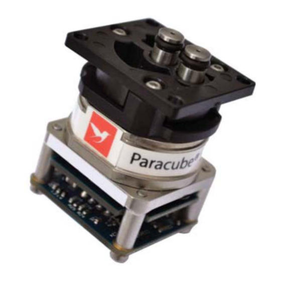
Introduction ® The Paracube Sprint represents the latest generation of Servomex’s paramagnetic sensing technology. The sensor takes advantage of recent technological advances allowing a performance only previously available from sensors of much greater size and cost. The sensor offers the OEM true flexibility in both mechanical and communication interfaces incorporating Servomex’s world renowned paramagnetic technology (described in section 2 of this manual) which has been designed into many OEM products where reliability, long life and performance are major considerations. -
Page 7: 2: Servomex Paramagnetic Measurement Principle
Servomex Paramagnetic Measurement Principle The sensor utilises the paramagnetic susceptibility of oxygen, a physical property which distinguishes oxygen from most other common gases. The sensor incorporates two nitrogen-filled glass spheres mounted on a strong, noble metal taut-band suspension. This assembly, termed the “Suspension Assembly” is suspended in a symmetrical non-uniform magnetic field. - Page 8 Current measurement Amplifier Conductive wire Rotation Photodiodes Mirror Light source Fig.2 In addition, the electromagnetic feedback stabilises the suspension (heavily damping oscillations) thus making it resilient to shock and vibration. 8 of 43 00501001A _ 2...
-
Page 9: 3: Product Specification
Product Specification Performance Specification (under constant conditions) This specification applies when the sensor has been calibrated using standard gas values of N and 100% O using the calibration procedure described in section 5. Unless otherwise stated, the performance figures quoted are derived from two standard deviation analysis. - Page 10 Response Time Rise Time (t Gas Exchange Sample Flow Rate Response Time 50mL.min 1,150 ms 120mL.min 395 ms 16% - 21%O 190mL.min 230 ms 250mL.min 170 ms 50mL.min 1,300 ms 120mL.min 560 ms 21% - 100%O 190mL.min 370 ms 250mL.min 280 ms Fall Time (t Gas Exchange...
-
Page 11: Mechanical Specification
Time to Valid Reading Time to valid output (from power up when within environmental spec) <6 seconds Time to status output (from power up when outside environmental spec) < 6seconds Pressure Compensation <0.8% of reading for 20kPag (±3psig), change from calibration point. Mechanical Specification Dimensions (W X D X H) The mechanical dimensions of all available sensor variants are detailed in appendix... -
Page 12: Environmental Specification
Environmental Specification Sample Gas Condition Dry, non-corrosive, non-flammable gas, free of entrained oil, less than 3 micron particulates, non-condensing, dew point 10°C below the sensor operating temperature. Pressure Effect The oxygen output will change in direct proportion to the barometric pressure unless pressure compensation is enabled (see variant options, table 7). - Page 13 Interference Effects The paramagnetic effect of common background gases at 20 C, for 100% concentration is shown below: Interfering Gas Interference Effect (100% Interferent) (% O -0.20 -0.26 -0.03 Methane -0.16 0.06 Helium 0.29 42.56 5.00 A comprehensive list detailing the effect of other background gases is outlined in appendix 7.4 or in Servomex Application Note HBAN PM25 13 of 43 00501001A _ 2...
-
Page 14: 4: Sensor Integration
Sensor Integration Sensor Mounting The sensor can be mounted in one of two ways depending on the variant chosen. If the gas interface is via barbed connectors refer to fig. 3, if the gas interface is via OEM supplied or Servomex fitted piston seal gas ports refer to figs. 4 and 5 respectively. - Page 15 The sensor mounting method shown in figs. 4 and 5 is via the 4 off 3.2mm diameter clearance holes located on the corners of the flanged moulding. The holes are on 24.7mm and 28.2mm centres. Fixing is achieved using one of the following two methods; 1.
- Page 16 Fig. 5 Flange mounted – gas connection via Servomex supplied gas ports CAUTION – No. 2 To ensure a gas tight seal for either of the flange type mounting methods, tighten the fixing screws to a torque value of 0.35 to 0.45 Nm. CAUTION –...
-
Page 17: Electrical Arrangement
Electrical Arrangement Power Supply (to be provided by the OEM) The sensor requires an external power supply as specified in Section 3.3. Electrical Connection Connection to the sensor is made via a 4 way connector mounted onto the sensor’s PCB. There are two connector types offered as standard, a Molex KK type friction lock (fig. - Page 18 PCB Mounted SMT Connector - Molex Part Number 532610471, fig. 6 1.25mm (.049") Pitch PicoBlade™ Header, Surface Mount, Right Angle. Mating crimp housing required by end-user Molex part number 0510210400 used in conjunction with crimp terminal part number 0500798000. Fig. 6 Earth/Ground Table 1 Earthing Arrangement...
-
Page 19: Communication And Output
Communication and Output UART Compatible communication The communication is bi-directional UART compatible (non-return to zero) at 19200 baud. There is one dedicated transmit line and one dedicated receive line. Sensor serial communications summary: Non return to zero format (NRZ) 0 & 5 Volt signalling voltages Full duplex 19200-baud transmission rate 8 data bits... -
Page 20: Location Of Sensor
Location of Sensor The sensor body should be fixed rigidly to the OEM assembly and away from vibrating components and in particular, care should be taken to avoid mounting the sensor onto a chassis or plate that may act as a lever or spring. If the OEM equipment is subjected to excessive mechanical shocks and vibration during use, it may be necessary to mount the sensor on shock absorbers to dampen the impact on the output of the sensor. -
Page 21: Orientation Of Sensor
Orientation of Sensor Change in Orientation To achieve optimum performance, the sensor should be operated in the orientation of calibration. Any small offsets resulting from a change in orientation may be removed by performing a single point or full calibration. Conditioning of the Sample The purpose of the sampling system is to convey clean sample gas to the sensor and attention should be paid to the following areas when designing a pneumatic system:... -
Page 22: Pressure Effects
Pressure Effects: The sensor is a partial pressure device and variations in sample gas pressure will cause fluctuations in the observed oxygen output, proportional to the pressure change. Under these circumstances the following methods maybe employed to mitigate this effect. Method 1 –... -
Page 23: Use Of Sensor With Flammable / Toxic Sample Gases
Method 3 – With Sensor’s On-board Pressure Compensation Disabled In some cases it may be desirable for the end user to perform their own pressure compensation. During sensor calibration, the span gas value and pressure reading should be recorded. These values may then be used to correct the oxygen signal for changes in sample pressure (if sensor is housed in a closed sample system) or barometric pressure (if sensor is open to ambient conditions) according to the following formula (applies if both calibration points are set at the same pressure):... - Page 24 Figure 7 1. Barbed Gas Ports - Sample gas connection to sensors fitted with barbed connectors is made via 1mm nominal I/D flexible tubing. The recommended ® material for the tubing is Tygon 2. OEM designed piston seal- Reference to fig. 4 shows the sensor’s gas interface with two 6.0/6.1mm diameter x 4.40+/- 0.1mm deep counter bores.
-
Page 25: 5: Operation And Calibration
Operation and Calibration ® Servomex calibrates the Paracube Sprint prior to shipment; however you are advised to recalibrate the sensor immediately prior to use to remove any offsets that may have occurred between shipment and installation. You may employ one of two calibration methods offered by the sensor’s software; a full “Two Point Calibration”... -
Page 26: Two Point Full Calibration
Two Point Full Calibration A full calibration of the sensor can be completed by using two gases which have a minimum oxygen concentration difference of 20%. Follow the example given in “Flow Chart 1” below for the procedure of a typical calibration. The command set is described in table 6. -
Page 27: Single Point Offset Correction (Spoc)
Single Point Offset Correction (SPOC) Expose the sensor to a known gas concentration in the range 0.0% O to 100.0% O for a minimum of 30s. Send the command !Snnn.n to perform the SPOC, where nnn.n is the known gas concentration. While the sensor performs the SPOC, each line of output from the sensor will contain a single ‘S’. -
Page 28: Zero Drift Offset Correction In The Host Equipment
If you are using a sensor variant that has pressure compensation disabled, oxygen concentration values reported by the sensor are compensated relative to the factory calibration pressure of 100kPa. To correct the oxygen reading following a SPOC, you will need to measure the sample gas pressure, and compensate using the expression for pressure compensation detailed in method 3 of section 4.9. -
Page 29: Led Sensor Status
LED sensor status The dual colour LED located on upper circuit board provides a visible indication of the calibration status or the sensor’s health. 1. Under normal operating conditions and with valid calibration data the LED will emit a constant green light. 2. -
Page 30: Format Of The Sensor Output
Format of the Sensor Output Table 3 below describes the format of the sensor’s output ASCII Normal use for a Alternative Usage Character Character in this (dependent on measurement and sensor Position Position status) Hundreds Digit Replaced by space instead of leading zero for readings <100 Could show minus sign for negative readings Will show X if a fatal failure is detected... -
Page 31: Status Flags
Status Flags Table 4 below details the error flags and the possible causes. Status Possible Cause Recommended Action Flag Electrical or sensing element Return sensor to Servomex malfunction Sensor exposed to extreme Return sensor to Servomex temperatures Sensor is being operated outside of Check environmental operating specification or signal levels are conditions including physical mount. -
Page 32: Sample Output Scenarios
Sample Output Scenarios The following table shows a number of examples of the output to indicate the positioning of the measurement and status flags under various conditions. Note: In the table below the symbol signifies a carriage return character. CP-1…..9 = character positions 1 through 9 of the sensor output. -
Page 33: Digital Interface Commands
Calibrating with CRC Space Space Space Space Space Space Space option Fatal Failure with CRC Space Space Space Space Space Space Space option Table 5 B, C and E flags may coexist. S, X flags are prioritised such that X has a higher priority than S. 5.10 Digital Interface Commands The digital interface provides commands that allow information to be read and for certain actions to be invoked. - Page 34 Read if internal pressure None Displays 0 if internal pressure compensation is disabled or 1 compensation is if it is enabled enabled or disabled Enable or disable Where n is, Enables or disabled internal pressure compensation being internal pressure 0 to disable pressure compensation applied to the reported oxygen measurement compensation...
-
Page 35: 6: Variants, Spares, Packaging And Warranty
Variants, spares, packaging and warranty Sensor Variants Options – As Shipped from Servomex Variant part numbers: Lists Digital only for Analogue see manual Pt. No. 00501009A Analogue Analogue Product KK friction Ext. Digital Output Output Int. Press. Variant lock Press. output 0.5mV/% 10.0mV/%... -
Page 36: Spares
Spares The sensor has no serviceable parts. Instruction Manual Digital variants, part number 00501001A Instruction Manual Analogue variants, part number 00501009A Special Packaging The sensor is manufactured in Class 10,000 clean room conditions. The sensor is fitted into anti-static packaging for transport, and it is recommended that the sensor is stored in this packaging until required for production. -
Page 37: Decontamination
Decontamination It is important that only general purpose alcohol based cleaning agents be applied ® to the external surfaces of the Paracube Sprint. NOTE: Contaminated cells should be disposed of in accordance with the local Environmental and Health & Safety regulations. Servomex reserves the right to refuse to examine product returned without a completed Decontamination Clearance Certificate. -
Page 38: 7: Appendices
Appendices Appendix 7.1 Outline Dimensions, Face seal with/without gas ports as required 38 of 43 00501001A _ 2... -
Page 39: Appendix 7.2 Outline Dimensions, Bracket Mount With Barbed Gas Ports
Appendix 7.2 Outline Dimensions, Bracket mount with barbed gas ports 39 of 43 00501001A _ 2... -
Page 40: Appendix 7.3 Mechanical Vibration And Shock Resistance
Appendix 7.3 Mechanical Vibration and Shock Resistance The sensor will meet the requirements of the following clauses of the International Standard IEC 68-2 Basic Environmental Testing Procedures. BS EN 60068-2-27:1993 (IEC 68-2-27) Shock Peak acceleration: 100g (980 ms Duration: 6 ms Pulse shape: Half sine BS EN 60068-2-6:1996 (IEC 68-2-6) Sinusoidal Vibration... -
Page 41: Sample Gas Cross Sensitivity Guide
Appendix 7.4 Sample Gas Cross Sensitivity Guide Formula Formula Acetylene HCCH Freon 114 Alkyl alcohol CHCH Halothane HBrClF3 Argon Helium Benzene C6H6 n-Heptane C7H16 1,2 Butadiene C4H6 n-Hexane C6H14 1,3 Butadiene C4H6 Hydrogen n-Butane C4H10 Isoflurane (Forane) F5ClO iso-Butane (CH3) CHCH Krypton iso-Butylene... - Page 42 Dichloroethylene (CHCl) n-Pentane C5H1 CCl3F Phenol Freon 11 C6H5OH Freon 12 Propane C3H8 Freon 113 CHCl iso-Propanol (CH3) CHOH Enflurane(Ethrane) F5ClO Propene CH3CH=CH Ethane Propylene C3H6 Ethanol H5OH Styrene C6H5CH=CH Ethyl acetate CH3COOC Tetrachoroethylene C=CCl Ethyl chloride H5Cl Vinyl chloride =CHCl Ethylene Xenon...
Need help?
Do you have a question about the Paracube Sprint and is the answer not in the manual?
Questions and answers