Table of Contents
Advertisement
Advertisement
Table of Contents

Related Manuals for KEHUA TECH SPI-B2 Series


Summary of Contents for KEHUA TECH SPI-B2 Series
- Page 1 PV Grid-Connected Inverter SPI-B2 Series (1500-6000) User Manual...
- Page 2 PV Grid-Connected Inverter SPI-B2 Series (1500-6000) Foreword User Manual Copyright © Xiamen Kehua Digital Energy Tech Co., Ltd2021. All rights reserved. No part of this document may be reproduced or transmitted in any form or by any means without prior written consent of Xiamen Kehua Digital Energy Tech Co., Ltd...
- Page 3 Thank you for choosing Kehua’s string PV Grid-Connected Inverter (hereinafter referred to as the “inverter”). This document gives a description of the SPI-B2 series inverter, including the features, performance, appearance, structure, working principles, installation, operation and maintenance.etc. Please save the manual after reading, in order to consult in the future.
- Page 4 PV Grid-Connected Inverter SPI-B2 Series (1500-6000) Foreword User Manual Symbol Description Provides a tip that may help you solve a problem or save time. Provides additional information to emphasize or supplement important points in the main text. Product standard: NB/T 32004-2013 Co.,Ltd...
-
Page 5: Table Of Contents
PV Grid-Connected Inverter SPI-B2 Series (1500-6000) User Manual Contents Contents 1 Safety Description......................... 1 1.1 Safety Announcements ............................1 1.1.1 Safety Instructions ............................ 1 1.1.2 Protection for PV Array ..........................3 1.1.3 Anti-Static Protection ..........................3 1.1.4 Grounding Requirements ......................... 3 1.1.5 Moisture-proofProtection ......................... - Page 6 PV Grid-Connected Inverter SPI-B2 Series (1500-6000) Contents User Manual 3.2.2 Installation Environment ........................13 3.2.3 Installation Space ........................... 14 3.2.4 Installation Way ............................15 3.3 Transportation and unpacking ......................... 15 3.3.1 Transportation ............................15 3.3.2 Unpacking and Checking ........................16 3.4 Installation ...............................
- Page 7 PV Grid-Connected Inverter SPI-B2 Series (1500-6000) User Manual Contents 6.2 Troubleshooting ............................... 41 6.3 Australian Standard Special Instructions ......................44 6.3.1 Ground Fault Instructions ........................44 6.3.2 PV/QV Mode Setting Instructions ......................44 6.3.3 WIFI Connection and APP Operation Mode ..................47 6.3.4 Additional RCDInstructions ........................
-
Page 9: Safety Description
PV Grid-Connected Inverter SPI-B2 Series (1500-6000) User Manual 1Safety Description 1 Safety Description This chapter introduces the safety announcements. Please read this user manual carefully prior to installing the inverter. It provides important information on safe and efficient installation. 1.1 Safety Announcements Before operation, please read the announcements and operation instructions in this part, which is to avoid accident. - Page 10 PV Grid-Connected Inverter SPI-B2 Series (1500-6000) 1Safety Description User Manual There is no operational part inside the inverter. Please do not open the crust of the inverter by yourself, or it may cause electric shock. The inverter damage caused by illegal operation is out of the guarantee range.
-
Page 11: Protection For Pv Array
PV Grid-Connected Inverter SPI-B2 Series (1500-6000) User Manual 1Safety Description In case fire, please use dry power fire extinguisher. If using liquid fire extinguisher, it may cause electric shock. 1.1.2 Protection for PV Array When install the PV array in the daytime, use light-proof material to cover the PV array, or, under the sunshine, the PV array will generate high voltage. -
Page 12: Moisture-Proofprotection
PV Grid-Connected Inverter SPI-B2 Series (1500-6000) 1Safety Description User Manual The device must be connected with protection earthing permanently. Before operating, please check the electric connection and ensure the device has been connected to earth reliably. 1.1.5 Moisture-proof Protection Moisture incursion may cause the inverter damage! For normal use of the energy-storage converter, please comply with the following items. -
Page 13: Measure With Electricity
PV Grid-Connected Inverter SPI-B2 Series (1500-6000) User Manual 1Safety Description 1.1.8 Measure with Electricity There is dangerous high voltage, contacting by accident may lead to deadly danger. So, when measure with electricity, it is necessary to do the protection (such as wear insulated gloves, etc.) The measure meter must accord with the following requirements. - Page 14 PV Grid-Connected Inverter SPI-B2 Series (1500-6000) 1Safety Description User Manual The used environment may influence the service life and reliability of the inverter. So, please avoid using the inverter in the following environment for long time. The place where beyond the specification (normal work temperature:-30℃~60℃, relative humidity: 0%-95%).
-
Page 15: Overview
PV Grid-Connected Inverter SPI-B2 Series (1500-6000) User Manual 2Overview 2 Overview This chapter mainly introduces the inverter features, appearance, operation panel, work principle, etc. 2.1 Product Intro The inverter is the device that converts DC energy from solar array into AC energy and then feedbacks to power grid. -
Page 16: Appearance And Structure
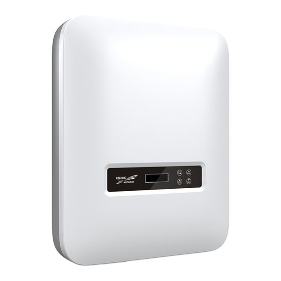
PV Grid-Connected Inverter SPI-B2 Series (1500-6000) 2Overview User Manual Better adaptability: with better grid adaptability, wide reactive power adjusting range. 2.2 Appearance and Structure The appearance of the inverter is as shown in Figure2-3. Figure2-3 Appearance of the inverter 2.2.1 Operation Panel... -
Page 17: External Terminal Illustration
PV Grid-Connected Inverter SPI-B2 Series (1500-6000) User Manual 2Overview Mark Illustration Remarks (red) Off: there is no fault. Short press: move the cursor upward or increase the setting value. ○ ESC button Long press: back to previous menu or cancel the current command. -
Page 18: Work Principle
PV Grid-Connected Inverter SPI-B2 Series (1500-6000) 2Overview User Manual Mark Illustration Remarks pairs of DC terminals (+,-) It is used to monitor the running status of the WIFI/GPRS WIFI/GPRS port inverter. Connect with DRM, COM. Optional METER GRID AC output terminal It is used to connect with grid. - Page 19 PV Grid-Connected Inverter SPI-B2 Series (1500-6000) User Manual 2Overview Boost Inverter circuit circuit GRID Figure2-6 Work principle diagram of SPI1500-B2, SPI2000-B2 Boost circuit 1 Inverter circuit GRID Boost circuit 2 Figure2-7 Work principle diagram of SPI3000-B2, SPI3600-B2, SPI4000-B2, SPI4600-B2, SPI5000-B2, SPI6000-B2 Co.,Ltd...
-
Page 20: Installation Guide
PV Grid-Connected Inverter SPI-B2 Series (1500-6000) 3Installation Guide User Manual 3 Installation Guide This chapter introduces the installation of the inverter, including installation process, installation preparation, transportation and unpacking, installation procedure, electrical connection and checking, etc. 3.1 Installation Process Start... -
Page 21: Installation Environment
PV Grid-Connected Inverter SPI-B2 Series (1500-6000) User Manual 3Installation Guide Tools The installation tools must be insulated to avoid electric shock. 3.2.2 Installation Environment Do not install the inverter in the place with poor ventilation. Ensure that there has sufficient fresh-air supply around the inverter. -
Page 22: Installation Space
PV Grid-Connected Inverter SPI-B2 Series (1500-6000) 3Installation Guide User Manual Recommended installation direction: do not install the inverter under directly sunshine. The countries in southern hemisphere (such as Australia, New Zealand) cannot install the inverter towards north, the countries in northern hemisphere (such as the Netherlands, Spain) cannot install the inverter towards south. -
Page 23: Installation Way
PV Grid-Connected Inverter SPI-B2 Series (1500-6000) User Manual 3Installation Guide Figure3-3 Installation space (unit: mm) 3.2.4 Installation Way Figure3-4 Installation way 3.3 Transportation and unpacking 3.3.1 Transportation The inverter should be transported by trained professional. During transporting, please take care and avoid impacting or dropping. -
Page 24: Unpacking And Checking
PV Grid-Connected Inverter SPI-B2 Series (1500-6000) 3Installation Guide User Manual 3.3.2 Unpacking and Checking Select the unpacking site in advance. In principle, the unpacking site should be as close to the installation site as possible. The inverter has been tested and checked strictly, but it still may be damaged during transporting, so, please check it carefully. -
Page 25: Installation
PV Grid-Connected Inverter SPI-B2 Series (1500-6000) User Manual 3Installation Guide 3.4 Installation The inverter can be installed on the wall or metal holder through equipped installation holder. Vertical installation is perfect. If it should be tilt, the vertical gradient should not exceed ±15°. - Page 26 PV Grid-Connected Inverter SPI-B2 Series (1500-6000) 3Installation Guide User Manual When installation, please keep the installation holder horizontal. Figure3-8 Mark the drilling position The depth of drilled holes should be within 45~55mm. Clear the dust and measure the net depth. Ensure that the depth of four holes is the same.
- Page 27 PV Grid-Connected Inverter SPI-B2 Series (1500-6000) User Manual 3Installation Guide Figure3-10 Fasten the installation holder Step 5 Uplift the inverter and hang the inverter to the installation holder, as shown in Figure3-11. Do not loosen the inverter until the inverter has been hang in the installation holder completely.
-
Page 28: Electrical Connection
PV Grid-Connected Inverter SPI-B2 Series (1500-6000) 3Installation Guide User Manual Figure3-12 Fasten the inverter Figure3-13 Position of lock (the lock customer provided) ----End 3.5 Electrical Connection 3.5.1 Wire Requirement The wiring of the inverter is all at the bottom, as shown in Figure2-5and Table2-2. The corresponding recommended wire specification as shown in Table3-1. -
Page 29: External Groundingconnection
PV Grid-Connected Inverter SPI-B2 Series (1500-6000) User Manual 3Installation Guide 3.5.2 External Grounding Connection ○ The external grounding terminal is as shown in Figure2-5 The external grounding wire cannot replace the PE wire of AC output terminal, they must be connected with ground reliably. -
Page 30: Dc Input (Pv) Connection
PV Grid-Connected Inverter SPI-B2 Series (1500-6000) 3Installation Guide User Manual 3.5.3 DC Input (PV) Connection When installation, it must use the equipped DC terminals to avoid inverter damage. It is recommended to use independent breaker for each PV input, and before connecting, the breakers must be off. - Page 31 PV Grid-Connected Inverter SPI-B2 Series (1500-6000) User Manual 3Installation Guide Figure3-17 Crimp the metal terminal Step 3 Insert the positive wire and negative wire into corresponding insulation crust respectively. If there has a click sound, it means that the wire have been inserted properly, as shown in Figure3-18.
-
Page 32: Ac Output (Grid) Connection
PV Grid-Connected Inverter SPI-B2 Series (1500-6000) 3Installation Guide User Manual Figure3-20 Connect the DC connector ----End 3.5.4 AC Output (GRID) Connection It's forbidden that several inverters shares an AC switch. It's forbidden to connect with load between inverter and AC switch. - Page 33 PV Grid-Connected Inverter SPI-B2 Series (1500-6000) User Manual 3Installation Guide Model Specification SPI6000-B2 During wiring, please pay attention to distinguish the AC live wire, neutral wire and grounding wire. Step 1 Strip the insulation layer of AC live wire (L), neutral wire (N) and grounding wire (PE) for about 7mm, as shown in Figure3-21.
- Page 34 PV Grid-Connected Inverter SPI-B2 Series (1500-6000) 3Installation Guide User Manual Figure3-23 Connect the wires of AC connector There is L, N, PE mark on the AC connector, the wire connection must be accord with the mark correspondingly. Step 3 Insert the AC connector to the GRID port (as shown in Figure3-24) and lock it.
-
Page 35: Wifi/Gprs Connection
PV Grid-Connected Inverter SPI-B2 Series (1500-6000) User Manual 3Installation Guide 3.5.5 WIFI/GPRS Connection If the inverter is equipped with WIFI/GPRS, insert it to the WIFI/GPRS port (as shown in Figure3-25 ) to monitor on the internet. The monitor way is as shown in Figure3-26. - Page 36 PV Grid-Connected Inverter SPI-B2 Series (1500-6000) 3Installation Guide User Manual 1--8 RJ45 port RJ45 plug Pin definition of RJ45 plug: PIN 1: White orange - DRM 5 1 2 3 4 5 6 7 8 PIN 2: Orange - DRM 6...
- Page 37 PV Grid-Connected Inverter SPI-B2 Series (1500-6000) User Manual 3Installation Guide The communication procedure of COM. port is as follows. Step 1 Strip the insulation layer of communication wire, unscrew the lock nut of waterproof RJ45 port (as shown in Figure3-29) and then lead the communication wire go through the RJ45 port and crimp it to the RJ45 plug..
-
Page 38: Check The Installation
PV Grid-Connected Inverter SPI-B2 Series (1500-6000) 3Installation Guide User Manual 3.6 Check the Installation After installation, check the following items: Check if the connection of DC input, AC output and communication wire are right. Check if the inverter is installed firmly. -
Page 39: Lcd Operation
PV Grid-Connected Inverter SPI-B2 Series (1500-6000) User Manual 4LCD Operation 4 LCD Operation This chapter introduces the operation of LCD. 4.1 First Startup When first power on, if it shows the power-on password page, as shown in Figure4-1, please contact the agent to obtain the startup password. -
Page 40: Main Menu Page
PV Grid-Connected Inverter SPI-B2 Series (1500-6000) 4LCD Operation User Manual 17/01/01 12:00 E_total 000.0kWh Figure4-4 Grid-connected main page (2) 17/01/01 12:00 P_out 0.00kW Figure4-5 Grid-connected main page (3) Table4-2 Button function on main page Button Function Long press: enter main menu 4.3 Main Menu Page... -
Page 41: Running Information
PV Grid-Connected Inverter SPI-B2 Series (1500-6000) User Manual 4LCD Operation Button Function Short press: move the cursor downward Long press: enter sub-menu 4.3.1 Running Information In main menu page, select Running Info, the LCD will show the running information, as shown in Figure4-9 to Figure4-13, corresponding button function is as shown inTable4-4. -
Page 42: Power Query
PV Grid-Connected Inverter SPI-B2 Series (1500-6000) 4LCD Operation User Manual 4.3.2 Power Query In main menu page, select Power Query, the LCD will show the power query page. In this page, it shows the daily power and total power, as shown in Figure4-14, corresponding button function is as shown inTable4-5. - Page 43 PV Grid-Connected Inverter SPI-B2 Series (1500-6000) User Manual 4LCD Operation Detailed fault info and dispose method please see Table6-1. 17/01/01 001: 12:00:00 U5010 Figure4-19 User log page Table4-6 Corresponding list of user log code and information User log code User log information...
-
Page 44: System Setting
PV Grid-Connected Inverter SPI-B2 Series (1500-6000) 4LCD Operation User Manual Table4-8 Button function on record query page Button Function Short press: move the cursor upward, or add the checked record No. Long press: back to previous menu page Short press: move the cursor downward, or reduce the checked record No. - Page 45 PV Grid-Connected Inverter SPI-B2 Series (1500-6000) User Manual 4LCD Operation Table4-10 Button function on login page Button Function Short press: add number value Long press: clear enter value, and back to user authority page Short press: reduce number value Long press: confirm the current entering, and the cursor move to right The general user can set following items: date &...
- Page 46 PV Grid-Connected Inverter SPI-B2 Series (1500-6000) 4LCD Operation User Manual △ > Power Cali Engineer Set Figure4-27 General user setting page 3 Engineer setting includes active power, reactive power, power factor, ISO protect, PV parallel mode, soft start, anti-countercurrent power,10min voltage, overvoltage protection point, overvoltage recover point,...
-
Page 47: System Information
PV Grid-Connected Inverter SPI-B2 Series (1500-6000) User Manual 4LCD Operation 4.3.5 System Information In main menu page, select System Info, the LCD will show the system information, as shown in Figure4-31 to Figure4-36, corresponding button function is as shown inTable4-12. -
Page 48: Startup And Shutdown
PV Grid-Connected Inverter SPI-B2 Series (1500-6000) 5Startup and shutdown User Manual 5 Startup and shutdown This chapter introduces how to start and shut down the inverter. 5.1 Startup Step 1 Switch on the DC Isolator and DC Isolator in the project site. When the PV arrays provide enough startup voltage, the LCD will enter the main interface. -
Page 49: Maintenance And Troubleshooting
PV Grid-Connected Inverter SPI-B2 Series (1500-6000) User Manual 6Maintenance and Troubleshooting 6 Maintenance and Troubleshooting This chapter mainly introduces the maintenance and troubleshooting for the inverter. 6.1 Maintenance The inverter needn’t to be maintained regularly, but the sundries or dust may influence the heat dissipation performance, so, use soft brush to clean the inverter.If the surface of LCD and LED... - Page 50 PV Grid-Connected Inverter SPI-B2 Series (1500-6000) 6Maintenance and Troubleshooting User Manual Code Fault information Solution Check the local grid voltage. If they are all normal, please contact local distributor. Check if the safety provision of the inverter meets the local grid-connected requirement.
- Page 51 PV Grid-Connected Inverter SPI-B2 Series (1500-6000) User Manual 6Maintenance and Troubleshooting Code Fault information Solution local distributor. Check the radiator, and see if it is blocked Radiator over- Check the environment temperature and see if the temperature E046 temperature exceeds the normal range.
-
Page 52: Australian Standard Special Instructions
PV Grid-Connected Inverter SPI-B2 Series (1500-6000) 6Maintenance and Troubleshooting User Manual 6.3 Australian Standard Special Instructions 6.3.1 Ground Fault Instructions The inverter complies with the requirements of IEC 62109-2 article 13.9 on ground fault alarm monitoring. When the ground fault alarm occurs outside the inverter, the detection circuit inside the inverter can act in time, and the LED Alarm indicator light on, and the fault code "E047"... - Page 53 PV Grid-Connected Inverter SPI-B2 Series (1500-6000) User Manual 6Maintenance and Troubleshooting For the single-phase Inverter (SPI1500-B2、 SPI2000-B2、SPI3000-B2、 SPI3600-B2、 SPI4000-B2、 SPI4600-B2、SPI5000-B2、SPI6000-B2), the default grid voltage in Australia is 230V, if customer need to set QV to 258V, then the value should be set as 112.3%.
- Page 54 PV Grid-Connected Inverter SPI-B2 Series (1500-6000) 6Maintenance and Troubleshooting User Manual The inverter is expected to provide a volt-var response as perFigure6-3. Figure6-3 Example curve for the volt-war control mode The default setting for the volt-war control mode is as shown in Table6-3.
-
Page 55: Wifi Connection And App Operation Mode
PV Grid-Connected Inverter SPI-B2 Series (1500-6000) User Manual 6Maintenance and Troubleshooting However, if the problem persists after setting, we recommend that the customer should contact local network operator to inspect line voltage. 6.3.3 WIFI Connection and APP Operation Mode See wiseSOLAR+ Operation Guide. -
Page 56: Package, Transportation And Storage
PV Grid-Connected Inverter SPI-B2 Series (1500-6000) 7Package, Transportation and Storage User Manual 7 Package, Transportation and Storage This chapter introduces the package, transportation and storage of the inverter. 7.1 Package The inverter is packaged by carton. When packaging, pay attention to the placing direction requirements. -
Page 57: A Technical Specifications
PV Grid-Connected Inverter SPI-B2 Series (1500-6000) User Manual A Technical Specifications Technical Specifications Model SPI1500 SPI2000 SPI3000 SPI3600 SPI4000 SPI4600 SPI5000 SPI6000 Item DC input Max. input power (W) 2025 2700 4050 4860 5400 6210 6750 8100 Vmax PV (d.c.V) - Page 58 PV Grid-Connected Inverter SPI-B2 Series (1500-6000) A Technical Specifications User Manual Model SPI1500 SPI2000 SPI3000 SPI3600 SPI4000 SPI4600 SPI5000 SPI6000 Item Grid voltage range (a.c.V) 180~280 Grid type Single-phase Rated output current (a.c.A) 6.5 13.0 15.7 17.4 20.0 21.7 26.0 Max.
- Page 59 PV Grid-Connected Inverter SPI-B2 Series (1500-6000) User Manual A Technical Specifications Model SPI1500 SPI2000 SPI3000 SPI3600 SPI4000 SPI4600 SPI5000 SPI6000 Item AC short-circuit protection Leakage current protection (RCD) DC isolation Optional PV Fault Detect Input DC impedance monitor Yes Surge protection Yes Class D, Piezoresistor Standard &...
- Page 60 PV Grid-Connected Inverter SPI-B2 Series (1500-6000) A Technical Specifications User Manual Model SPI1500 SPI2000 SPI3000 SPI3600 SPI4000 SPI4600 SPI5000 SPI6000 Item Inverter design Transformerless Display LCD display + LED indicator Communication RS485 /WIFI(optional)/GPRS(optional)/DRM (Australia) AC terminal Plug and play (max. 6mm²)
-
Page 61: B Acronyms And Abbreviations
PV Grid-Connected Inverter SPI-B2 Series (1500-6000) User Manual B Acronyms and Abbreviations Acronyms and Abbreviations Alternating Current Conformite Europeenne Direct Current International Electrotechnical Commission Liquid Crystal Display Light-emitting Diode MPPT Maximum Power Point Tracking Co.,Ltd All rights reserved ©Xiamen Kehua Digital Energy Tech... - Page 62 PV Grid-Connected Inverter SPI-B2 Series (1500-6000) B Acronyms and Abbreviations User Manual Protective Earthing Photovoltaic RS485 Recommend Standard485 THDi Total Distortion of the input current waveform Co.,Ltd All rights reserved ©Xiamen Kehua Digital Energy Tech...
Need help?
Do you have a question about the SPI-B2 Series and is the answer not in the manual?
Questions and answers
Grid error
A grid error for the KEHUA TECH SPI-B2 Series inverter, such as "Grid frequency E017 abnormal," indicates an issue with the local grid voltage or frequency. The user should check the local grid voltage. If the voltage and frequency are normal, the inverter may not meet local grid-connected requirements, and the user should contact the local distributor.
This answer is automatically generated