Table of Contents
Advertisement
ISTRUZIONI PER L'USO
INSTRUCTIONS FOR USE
MODE D'EMPLOI
GEBRAUCHSANWEISUNG
INSTRUCCIONES DE USO
KCF/B
KCF/P
KPLTB - KPLTW
KTLT
KRLT
KRLTI - KRLTM
Controllo elettronico per unità terminali
Electronic control for terminal units
Controle electronique pour unites terminales
Elektronische Steuerung für Inneneinheiten
Control electrónico para unidades terminales
H58545
English
Advertisement
Table of Contents

Related Manuals for RHOSS KCF/B

Summary of Contents for RHOSS KCF/B
- Page 1 ISTRUZIONI PER L’USO INSTRUCTIONS FOR USE MODE D’EMPLOI GEBRAUCHSANWEISUNG INSTRUCCIONES DE USO KCF/B KCF/P KPLTB - KPLTW KTLT KRLT KRLTI - KRLTM Controllo elettronico per unità terminali Electronic control for terminal units Controle electronique pour unites terminales Elektronische Steuerung für Inneneinheiten Control electrónico para unidades terminales...
- Page 2 Le istruzioni originali della presente pubblicazione sono in lingua italiana, le altre lingue sono una traduzione delle istruzioni originali. È vietata la riproduzione la memorizzazione e la trasmissione anche parziale della presente RHOSS pubblicazione, in qualsiasi forma, senza la preventiva autorizzazione scritta della S.p.A.
- Page 3 Arquà Polesine (RO), via delle Industrie 211, dichiara, sotto la propria esclusiva responsabilità, che i prodotti della serie KCF/P – KCF/B – KPLT- KTLT KRLT – KRLTI – KRLTM – KDO2 –KIF485 sono conformi alle disposizioni stabilite dalle seguenti direttive e norme armonizzate: - 2014/35/UE (LVD) Direttiva Bassa Tensione.
-
Page 4: Table Of Contents
ELECTRONIC CONTROL FOR TERMINAL UNITS INDEX SYMBOLS USED SYMBOL MEANING SECTION I :: USER ..................5 DANGER! The DANGER sign warns the operator and Features ........................5 maintenance personnel about risks that may cause I.1.1 Declared conditions of use .................... 6 death, physical injury, or immediate or latent I.1.2 Spare parts and accessories .................. -
Page 5: Isection I :: User
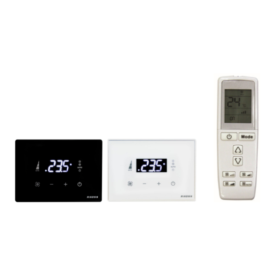
ELECTRONIC CONTROL FOR TERMINAL UNITS SECTION I :: USER FEATURES KCF/B - CF/B: KCF/P – CF/P: On board control complete with minimum On-board control complete with LED display water temperature probe and auxiliary relay for displaying the desired room temperature... -
Page 6: Declared Conditions Of Use
DECLARED CONDITIONS OF USE The electronic controls referred to in this manual are intended for use with the following RHOSS terminal units: YardyEV3, YardyDuct, Yardy- I, YardyID, YardyHp, DIVA, DIVA-I. These terminal units are not designed to be installed in rooms used for KRLTI - Infrared receiver card for KTLT remote control to be fixed on laundry purposes (IEC standard EN 60335-2-40). -
Page 7: Instructions For Use
ELECTRONIC CONTROL FOR TERMINAL UNITS INSTRUCTIONS FOR USE Minimum speed I.2.1 USING THE CONTROL PANEL Medium speed Maximum speed Automatic control of the speed I.2.1.4 Setting the desired temperature By pressing these keys it is possible to increase or decrease the desired temperature value. The display shows the value of the selected temperature. -
Page 8: Unit In Alarm Condition
ELECTRONIC CONTROL FOR TERMINAL UNITS I.2.3 USING THE REMOTE CONTROL (KTLT) I.2.2 UNIT IN ALARM CONDITION If there is an alarm due to a fault that prevents the appliance from operating, the control panel will show the alarm code on the display. The alarm display alternates with the display. -
Page 9: Wall Receiver (Krlt)
ELECTRONIC CONTROL FOR TERMINAL UNITS I.2.3.7 Batteries exhausted I.2.3.3 Setting the operating mode If the batteries are almost empty, the display will work normally, but the By pressing the Mode key several times, you can transmission of commands may not be performed correctly. Ensure that change the operating mode of the unit. -
Page 10: Receiver On Overlay For Diva (Krlti-Krltm)
ELECTRONIC CONTROL FOR TERMINAL UNITS I.2.4.1 Alarms If an alarm is present due to a fault that prevents the appliance from operating, the lighting of the LEDs allows to determine the type of alarm. In the event of more than one alarm, the alarm with the highest priority is displayed. -
Page 11: Section Ii: Installation
A non-compliant electrical connection lifts RHOSS Spa from liability concerning damage to objects and persons. Follow these instructions to remove the packaging: DANGER! ... -
Page 12: Ii.3.2 Connecting The Power Supply
ELECTRONIC CONTROL FOR TERMINAL UNITS II.3.2 CONNECTING THE POWER SUPPLY II.3.3 ADJUSTMENT FUNTIONS Check that the voltage and frequency of the electrical system correspond to 230V (± 10%) single phase at 50 / 60Hz, that the II.3.3.1 AUTO installed power is sufficient for operation and that the cables of the In AUTO the terminal unit detects the room temperature and decides power supply line have a section suitable for the current maximum which mode to activate (heating or cooling) based on the set point set... - Page 13 ELECTRONIC CONTROL FOR TERMINAL UNITS Fan and cold / hot water valve are operated as in cooling / heating. When the set point is satisfied, the cold / hot water valve is closed and II.3.3.3 the periodic ventilation function is activated (see dedicated paragraph). If the room temperature is inside the hysteresis zones at the input in FAN is the "ventilation"...
- Page 14 ELECTRONIC CONTROL FOR TERMINAL UNITS II.3.3.5 HEAT II.3.3.6 HEAT + RESISTANCE HEAT is the "heating" function. Even in this mode of operation, the The HEAT + ELECTRICAL RESISTANCE function provides for the regulation that expresses the most comfort can be set as desired by: HEAT operating mode with automatic activation of the electrical ...
- Page 15 ELECTRONIC CONTROL FOR TERMINAL UNITS II.3.3.7 RADIANT MANAGEMENT LOGIC Fancoil summer / winter + winter head contact (2tubi + radiante) This function is obtained by configuring the fancoil in 2tubi + radiant Four configurations are possible: (see Dip-switches configuration): the Out1 output activates the hot / cold water valve in two-pipe systems while the Out2 output activates the Fancoil summer / winter + winter head 2T + Radiator...
-
Page 16: Ii.3.4 Comfort Functions
ELECTRONIC CONTROL FOR TERMINAL UNITS II.3.4 COMFORT FUNCTIONS II.3.4.3 PERIODIC VENTILATION / CONTINUED IMPORTANT! II.3.4.1 TOO COOL To counteract the air stratification phenomenon, the terminal unit performs fan on / off cycles at For COOL operating mode, the TOO COOL function is provided, which minimum speed, even when the room temperature blocks the start of the fan if the temperature of the water entering the has reached the set point (the hot / cold valve... -
Page 17: Ii.3.5 Advanced Features
ELECTRONIC CONTROL FOR TERMINAL UNITS NOTE: the configuration of the inputs described above must be performed only on the master. II.3.5 ADVANCED FEATURES Dip-Switch: all the Dip Switchs present in the Slaves are II.3.5.1 Master/Slave connection considered. It is a particular function for which a control panel or receiver connected Timeout: The Slaves can not continue to operate without the Master to a fancoil Master, sends some information on the operation in (due to lack of communication, fault or other) as no command would be... - Page 18 ELECTRONIC CONTROL FOR TERMINAL UNITS II.3.5.2 ON / OFF remote control (SCR) II.3.5.5 ECONOMY (ECO) Digital input D1. Digital input D2 or D3. It is possible to control the device from a remote consent by means of a It is possible to operate the unit in ECONOMY mode by a remote time switch or a centralized system (clean contact).
-
Page 19: Dip-Switches Configurations
ELECTRONIC CONTROL FOR TERMINAL UNITS II.3.5.7 LOCK FUNCTION II.3.6 DIP-SWITCHES CONFIGURATIONS It allows a constrained management of the device in case of Changes to DIP-Switches must be made when the board is powered applications managed centrally (constrained conditioning). off. The function is enabled with the parameter LOC = 1. The DIP-Switches on the control board can be switched using a sharp In fact, it provides only the AUTO mode (or possibly EIR if enabled). -
Page 20: Auxiliary Contacts Of The Kdo2 Module
ELECTRONIC CONTROL FOR TERMINAL UNITS II.3.7 AUXILIARY CONTACTS OF THE KDO2 II.3.8 SETTING AND MODIFICATION OF MODULE PARAMETERS WITH CONTROL PANEL The KDO2 module has two auxiliary contacts (voltage-free contacts, dry The parameter map is resident in the touch control panel or on-board contacts) configurable by parameter: control panel: when this is connected to the base card, overwriting from - AUX1 - relay 8A AC1 230Vac max - normally open... -
Page 21: Setting And Modification Of Parameters With Receiver
ELECTRONIC CONTROL FOR TERMINAL UNITS II.3.9 SETTING AND MODIFICATION OF II.3.10 VISUALIZATION OF THE STATE OF THE PARAMETERS WITH RECEIVER UNITY The parameter map is resident in the basic card: when it is connected to the receiver, overwriting from the base card to the receiver takes You can access a quick menu that allows you to view some system place. -
Page 22: Ii.4 Instructions For Start-Up
3. the screws holding the cables are tightened well; SAFEGUARD THE ENVIRONMENT! 4. the supply voltage is as required; RHOSS S.p.A. has always cared about protecting 5. the absorption of the unit is correct and does not exceed the the environment. -
Page 23: Ii.7 Troubleshooting
ELECTRONIC CONTROL FOR TERMINAL UNITS II.7 TROUBLESHOOTING Anomaly Probable cause The automatic circuit breaker of the unit has been activated or deactivated. Voltage is lacking. A unit alarm has intervened (see I.2.4). The unit does not run: ... - Page 24 ALLEGATI / ENCLOSED DOCUMENTS / ANNEXES / ANLAGEN / ANEXOS SCHEMI ELETTRICI / WIRING DIAGRAMS / SCHÉMAS ÉLECTRIQUES / SCHALTPLÄNE / ESQUEMAS ELÉCTRICOS...
- Page 25 ALLEGATI / ENCLOSED DOCUMENTS / ANNEXES / ANLAGEN / ANEXOS...
- Page 26 ALLEGATI / ENCLOSED DOCUMENTS / ANNEXES / ANLAGEN / ANEXOS...
- Page 27 ALLEGATI / ENCLOSED DOCUMENTS / ANNEXES / ANLAGEN / ANEXOS...
- Page 28 ALLEGATI / ENCLOSED DOCUMENTS / ANNEXES / ANLAGEN / ANEXOS...
- Page 29 ALLEGATI / ENCLOSED DOCUMENTS / ANNEXES / ANLAGEN / ANEXOS...
- Page 30 ALLEGATI / ENCLOSED DOCUMENTS / ANNEXES / ANLAGEN / ANEXOS...
- Page 31 ALLEGATI / ENCLOSED DOCUMENTS / ANNEXES / ANLAGEN / ANEXOS...
- Page 32 ALLEGATI / ENCLOSED DOCUMENTS / ANNEXES / ANLAGEN / ANEXOS...
- Page 33 ALLEGATI / ENCLOSED DOCUMENTS / ANNEXES / ANLAGEN / ANEXOS...
- Page 34 ALLEGATI / ENCLOSED DOCUMENTS / ANNEXES / ANLAGEN / ANEXOS...
- Page 35 ALLEGATI / ENCLOSED DOCUMENTS / ANNEXES / ANLAGEN / ANEXOS...
- Page 36 ALLEGATI / ENCLOSED DOCUMENTS / ANNEXES / ANLAGEN / ANEXOS...
- Page 37 ALLEGATI / ENCLOSED DOCUMENTS / ANNEXES / ANLAGEN / ANEXOS...
- Page 38 KCF/B – KCF/P – KPLTB-KPLTW – KTLT – KRLT – KRLTI-KRLTM S.p.A. RHOSS Via Oltre Ferrovia - 33033 Codroipo (UD) Italia- tel. 0432.911611 - fax 0432.911600 - rhoss@rhoss.it www.rhoss.it H58545 06.18 PS/RM-LF...
Need help?
Do you have a question about the KCF/B and is the answer not in the manual?
Questions and answers