Advertisement
Quick Links
Allure™ EC‑Smart‑Vue Sensor Series
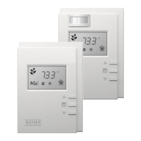
Figure 1:
(Left image) Allure EC Smart Vue, Allure EC Smart Vue-H/-C/-CH sensors. (Right image) Models equipped with a motion
sensing window in the upper left corner: Allure EC Smart Vue-M/-CM/-HM/-CHM sensors
Product Description
The Allure EC-Smart-Vue Series is designed to interface with Distech Controls' ECLYPSE™ series BACnet/IP and Wi-Fi Controllers, ECB series BAC-
®
net
Controllers and ECL series L
This line of communicating sensors with backlit display consists of eight models that provide precise environmental zone control. Models are available
with any combination of the following: temperature, humidity, CO
General Installation Requirements
For proper installation and subsequent operation of the device, pay special attention to the following recommendations:
£
Upon unpacking, inspect the contents of the carton for shipping damages. Do not install a damaged device.
£
Allow for proper clearance around the device's enclosure and wiring terminals to provide easy access for hardware configuration and maintenance.
£
Orient the device with the ventilation slots towards the top to permit proper heat dissipation.
£
Ensure proper ventilation of the device and avoid areas where corroding, deteriorating or explosive vapors, fumes or gases may be present.
Any type of modification to any Distech Controls product will void the product's warranty
Take reasonable precautions to prevent electrostatic discharge to the device when installing, servicing or during operation. Discharge
accumulated static electricity by touching one's hand to a well-grounded object before working with the device.
General Wiring Recommendations
Risk of Electric Shock: Turn off power before any kind of servicing to avoid electric shock.
£
All wiring must comply with electrical wiring diagrams as well as national and local electrical codes.
£
Comply with all network and power supply guidelines outlined in the Network Guide.
£
Use the screws, wall anchors, and wire nuts included for wall mounting and wiring.
®
W
Controllers.
ON
ORKS
2
, and motion sensor.
I n s t a l l a t i o n G u i d e
Advertisement

Related Manuals for Distech Controls Allure EC-Smart-Vue Series


Summary of Contents for Distech Controls Allure EC-Smart-Vue Series
- Page 1 (Left image) Allure EC Smart Vue, Allure EC Smart Vue-H/-C/-CH sensors. (Right image) Models equipped with a motion sensing window in the upper left corner: Allure EC Smart Vue-M/-CM/-HM/-CHM sensors Product Description The Allure EC-Smart-Vue Series is designed to interface with Distech Controls’ ECLYPSE™ series BACnet/IP and Wi-Fi Controllers, ECB series BAC- ® ®...
-
Page 2: Mounting Instructions
Mounting Instructions The Allure Allure EC-Smart-Vue has been specially designed for easy installation. However, certain conditions apply when choosing a suitable location for the device: £ Install the device in a location of average temperature approximately 5 ft (1.5 m) above the floor £... -
Page 3: Device Mounting
Device Mounting Wall Anchors Security Screw Figure 3: Mounting an Allure EC-Smart-Vue Sensor Connector and Jumper Location, Identification and Configuration Allure EC-Smart-Vue sensors have the following onsite configurable jumpers. Front Cover, Interior View Pass-Through Subnetwork RJ-45 Connectors PIR LED Enabled Disabled Motion Detection Models Only Subnetwork End of Line Enabled... - Page 4 Supported Quantity The Allure EC-Smart Vue sensor connects to the controller’s Subnet Port. Other expansion modules may also be connected to this port in a daisy- chained fashion (see the controller’s datasheet for compatibility information and supported quantities). Each controller supports a maximum number of Allure EC-Smart Vue sensors. The Subnet ID of all Allure EC-Smart Vue sensors must be set to be within the shown addressing range.
- Page 5 Subnetwork Bus Total Length The total maximum length of all Subnetwork buses, including both the length of the Allure Series Communicating Sensor Subnetwork bus and the ECx-400 Series Subnetwork bus is 300 m (1 000 ft). The maximum length of the Allure Series Communicating Sensor Subnetwork bus is 200 m (650 ft). The maximum length of the ECx-400 Series Subnetwork bus is 300 m (1 000 ft).
- Page 6 Subnetwork Bus Topology and EOL Terminations Only a daisy chain topology is acceptable for the room device subnetwork bus. T connections are not allowed. Some controller models support the connection of other devices to the Subnet Port as part of the Smart Room Control solution (see the controller’s datasheet for more information).
- Page 7 Cat 5e Cable Subnetwork Bus Controller: ECB-600 Inside ECL-600 Back of Controller Allure EC-Smart-Vue Sensor EOL OFF EOL ON EOL set to ON at the last For the controller, set the sensor at the Subnetwork EOL to ON end of the Bus Figure 9: Setting the EOL Terminations on the Allure EC-Smart-Vue Sensor for ECB-600 or ECL-600 Series controllers When ECx-400 Series I/O Extension Modules are installed with an ECB-600 or ECL-600 Series controller and with Allure Series Communicating Sen-...
- Page 8 Subnet ID to 1 as follows: 1. Connect an an Allure EC-Smart-Vue Series Communicating Sensor to the controller with a Cat 5e patch cable. Wait for the Bell icon and the number 1 to flash on the display.
- Page 9 ECB Series controller’s MAC Address as follows: Set the connected controller’s MAC Address as follows: 1. Connect an Allure EC-Smart-Vue Series Communicating Sensor to the controller with a Cat 5e patch cable. Wait for the display to show the room temperature.
- Page 10 Set the connected controller’s BAUD rate as follows: 1. Connect an Allure EC-Smart-Vue Series Communicating Sensor sensor to the controller with a Cat 5e patch cable. Wait for the display to show the room temperature. 2. Press and hold the Menu button for 5 seconds to enter the password menu.
- Page 11 Set the LAN Type Set the BAC/LON jumper for the type LAN in use: BAC for a BACnet network, LON for a L network. ORKS Network Type 3.5 mm (1/8”) Network Jumper Access Jack Figure 11: BAC/LON Jumper Set to the BAC (BACnet) Position when used with ECBSeries Controllers Network Type 3.5 mm (1/8”) Network Jumper...
- Page 12 7. To enter the GEN CFG submenu, press the down button once. 8. Press the Menu button several times until MOTION SENSITIVITY appears on the display. The current motion sensitivity level is shown. Screen Timeout: 30 seconds 9. Use the up and down buttons to set the motion sensitivity level to 0 (low), 1 (medium - typical default setting), or 2 (high).
- Page 13 Network Access from the Sensor ORKS For commissioning and maintenance purposes, the L network is optionally available from the Allure EC-Smart-Vue sensor audio plug port (not ORKS available with ECL-PTU series controllers, or the ECL-VAVS). Setting the two (2) Net to Subnet Port Settings jumpers inside the ECL Series controller to Enable will connect the main L network to the Allure ORKS EC-Smart-Vue sensor subnetwork Cat 5e cable.
- Page 14 Bus Network Topology: 22AWG (0.65mm) Unshielded Twisted Pair Network Cable For a Few Standard Net to Controller Controllers ONLY: Subnet Port Net to Subnet Port Settings Settings: Optionally Enabled DISABLED - this is the factory default setting Communicating Sensor Cat 5e Cable Subnetwork Bus Provides: ·...
-
Page 15: Troubleshooting
Sensor Subnet ID [pg. 8]. In EC- gfx Program, resynchronize the code with the controller. Flashing error code 2 with Bell icon Invalid configuration. Contact Distech Controls Customer Support. Flashing error code 3 with Bell icon Allure EC-Smart-Vue With EC- gfx Program, check the configuration of the sensor,... - Page 16 ©, Distech Controls Inc., 2010 - 2018. All rights reserved. Images are simulated. While all efforts have been made to verify the accuracy of information in this manual, Distech Controls is not responsible for damages or claims arising from the use of this manual.
Need help?
Do you have a question about the Allure EC-Smart-Vue Series and is the answer not in the manual?
Questions and answers