Table of Contents
Advertisement
Quick Links
Advertisement
Table of Contents

Summary of Contents for Datron TW7201I
- Page 1 TW7201I-MS TW7201I DHSL Remote Control Head Operator/Technical Manual Datron World Communications Inc. Manual Part No. TW7201I-MS Release Date: January 2008 Revision: E 3030 Enterprise Court Vista, CA 92081, U.S.A. Phone: (760) 597-1500 Fax: (760) 597-1510 E-Mail: sales@dtwc.com www.dtwc.com...
- Page 3 Change Description Date of Revision Pages Description of Changes Revision Letter Affected 01/08 Change ISDN designation to DHSL. TW7201I-MS...
- Page 5 Software, documentation, and All rights reserved. any copies of each to Datron. This Software is licensed “AS IS” and Datron provides a war- Datron World Communications, Inc. ranty that covers the media upon which the Software is embed- This manual, as well as the software described in it, is ded for a period of 30 days from receipt of the product.
- Page 6 Remedies: Buyer’s sole remedies and the entire liability of Datron are set forth above. In no event will Datron be liable to Buyer or any other person for any damages, including any incidental or consequential damages,...
-
Page 7: Table Of Contents
Chapter 1: Introduction The TW7201I DHSL Remote Control Head ......1-1 Specifications. - Page 8 TW7201I Subassemblies........
- Page 9 Figure 5-8 Switching Board Schematic Diagram (994149 Rev. A) ..... 5-45 Table 5-29 Switch Board Parts List (001-00110 Rev. A1) ......5-47 TW7201I-MS...
-
Page 11: The Tw7201I Dhsl Remote Control Head
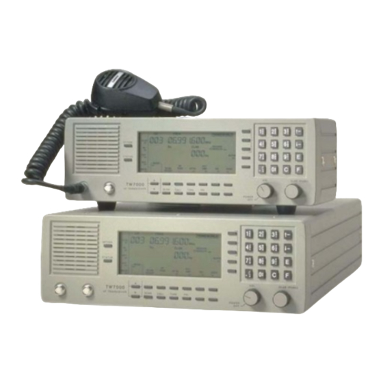
INTRODUCTION The TW7201I DHSL Remote Control Head The TW7201I is the Datron High Speed Link (DHSL) remote control unit that uses a high speed modem to provide remote operation of the TW7000 series transceivers configured with the 7000RI option over a two-wire line. The TW7201I includes a DHSL modem that communicates with its DHSL counterpart (7000RI modem option) in the TW7000(F) transceiver. -
Page 12: Specifications
2-wire (maximum distance 2 km). Physical Size (HWD) 10.16 cm x 33.02 cm x 15.24 cm. (4 in. x 13 in. x 6 in.). Weight 3.175 kg (7 lbs.). Environmental Temperature operating –30° C to +60° C. storage –40° C to +70° C. TW7201I-MS... -
Page 13: Tw7000 Series Family
Control controls, the transceiver controls are the master. In this case, the transceiver controls are live from the transceiver and TW7201I. For security and limited operation applications, the key functions can be inhibited at either the transceiver or TW7201I control panels. Two variations of the TW7000 series transceivers, the TW7000E and TW7000C, do not include control panels. -
Page 14: Manual Conventions
Both channels are high speed data channels with a 9600 N81 standard interface. Operating Modes The TW7201I is designed to be a high speed modem link to the transceiver for both voice and data. The high speed characteristic allows for a wide variety of voice and data capabilities. -
Page 15: Referenced Manuals
1: Introduction Referenced Manuals • RC2-MSOP Radio Control 2 Operator Manual • 7000ENCR-MSOP 7000-Series High-level Encryption Operator Manual • 7000ALE-MSOP 7000ALE Radio Control Program Operator Manual TW7201I-MS... -
Page 17: Installation Types
For vehicle and marine applications, the TW7201I can be ordered with mobile mounting brackets (TW7201MM) that are designed for either top or bottom mounting. For rack mount applications, the TW7201I can be ordered with the rack mount kit (TW7201RM). For local operation, the TW7201I requires a 2-wire line between the remote head and the transceiver. -
Page 18: Audio Connections
2: Installation Audio Connections The TW7201I front panel hosts two 6-pin microphone connectors. These two connectors are wired in parallel and are compatible with various audio accessories. The input impedance is 150 ohms (nominal). The TW7201I supports most dynamic, ceramic and magnetic microphones. -
Page 19: Rear Panel Description
Figure 2-3 TW7201I Rear Panel 2.4.1 Input Power The TW7201I can accept input power from either an AC or DC power source. AC Power The rear panel includes a standard IEC AC power connector that can be configured for 120 or 240 VAC. A standard AC power cable is included with the TW7201I (769004 IEC320 to NEMA 5-15). - Page 20 AC power connector. DC Power The TW7201I rear panel also includes a DC power connector and fuse holder. The DC input circuitry is designed for 13.8 Vdc with a typical current requirement of approximately 300 mA. The recommended DC voltage range is 12 Vdc to 16 Vdc.
- Page 21 An external encryption device can connect to either connector ACC 1 Devices ACC 2 Audio Interface Audio interface devices such as Datron’s ACU1000 and ACU-T can use either Devices accessory connector. DTEs The TW7201I can interface with data terminal equipment (computers) through accessory connector .
- Page 22 LANs and through the Internet. External Speaker The TW7201I includes a standard speaker mounted on the inside of the front panel. An external loudspeaker can be added to the transceiver through the accessory connector.
- Page 23 +12V ACC +12 Vdc supply for the accessory devices EXTCWKEY External CW key No connection Not used FPWSP1 Front panel spare port (not used) No connection No connection No connection No connection No connection No connection No connection No connection TW7201I-MS...
- Page 24 No connection Not used No connection No connection No connection TC/SCALM Transcall/Secall alarm No connection EXTSPKR External speaker audio No connection +12V ACC +12 Vdc supply for the accessory devices +12V ACC +12 Vdc supply for the accessory devices TW7201I-MS...
-
Page 25: Powering The Tw7201I
CHAPTER 3 OPERATION The procedures discussed in this chapter use the TW7201I front panel to program the TW7000 series transceiver. The TW7000 transceiver must be powered on to program the Note: transceiver from the TW7201I. To program the transceiver from a computer, refer to the Radio Control 2 Operator Manual (RC2-MSOP);... -
Page 26: Using Knobs, Buttons And Indicators
For the knob, button and indicator locations, refer to Figure 3-1 above. 3.2.1 Power/Volume knob provides power to the TW7201I. It also provides volume PWR/VOL control for the internal speaker. To increase volume, turn the PWR OFF/VOL knob clockwise. - Page 27 The arrows remain active until another control function is selected. Channel and , and buttons enter channel and frequency information into memory. Frequency To select a channel: Selection 1. Press the button. Enter the channel number using the keypad. TW7201I-MS...
- Page 28 Enter the frequency. Press to enter the frequency into memory. 3.2.4 Function The TW7201I front panel includes preprogrammed function buttons such as Buttons . The LCD displays the icons at the left and CALL SEND TUNE and ALPHA bottom section of the LCD.
- Page 29 Press the up or down arrow buttons MODE to scroll through the following choices. Mode Description Upper sideband voice: Standard voice grade IF filter and voice AGC time constants. Lower sideband voice: Standard voice grade IF filter and voice AGC time constants. TW7201I-MS...
- Page 30 STATUS If you press a button other than , the icon Note: OPTION STATUS stops flashing and the radio performs the function of that button. The icon also stops flashing after a time-out of 10 seconds. TW7201I-MS...
-
Page 31: Vswr Feature
After selecting and entering a function, use the arrow buttons on the keypad to scroll through any further selections within that function. Press to enter a selection. For example, press , then press to access the ALE submenu. ALPHA 17 TW7201I-MS... - Page 32 COM 1 BAUD (comport configuration). COM 2 BAUD (comport configuration). BACKLITE OUT (ON/OFF). FREQ INC HZ (frequency increment from 1 Hz to 10 MHz). TEST REAR PANEL I/O (factory test). ENC PASSWORD (Encryption menu). PTT TIMER (sets maximum PTT time). TW7201I-MS...
- Page 33 For changing RF power output settings of the TW7000. (5) RF POWER The defaults for the three power output levels are 10, 30, and 200. To change a value: 1. Connect a power meter to the antenna connector on the rear of the TW7000. TW7201I-MS...
- Page 34 (12) TIME AND DATE (13) TA/TS/SC Rx ADDR For selecting a self ID. The LCD briefly displays the current self ID. Use numbers from 000 to 255. This number is usually the last three digits of a serial number. 3-10 TW7201I-MS...
- Page 35 Section 3.11 “Activating Voice Enhancement” on page 3-26. For configuring the TW7000 COM1 port for (22) COM 1 BAUD communicating with a computer. Use the arrow buttons to scroll through and enter the baud rate, data bits, stop bits, and parity. TW7201I-MS 3-11...
- Page 36 • Polling is set to ) or • Alarm timer sets the interval in minutes between system polling from the receiver to the transmitter. • FP alarm activates the internal alarm when loss of communication occurs. Set to ) or 3-12 TW7201I-MS...
- Page 37 CALL LIM (call limit) SLF TMOUT (self time-out) OTR TMOUT (other time-out) AUTO FILL LQA EXCNG (Link Quality Analysis exchange) LQA DECAY (Link Quality Analysis decay) BER THRSD (BER threshold) GOLAY THD (Golay threshold) ERR THRSD (error threshold) TW7201I-MS 3-13...
- Page 38 For automatically tuning an ALE scan group (from 0 to (3) TUNE GRP 9). This tunes all the channels in the selected scan group. For selecting a receive type: (4) Rx SELCT • for normal ALE receive/transmit ( Rx/Tx • for receive only ( Rx ONLY 3-14 TW7201I-MS...
- Page 39 For setting the length of each sounding transmission. (12) SND LEN The recommended sounding length is 5 or 10 seconds. For setting the time intervals for sounding. Enter from (13) SND INT 1 minute to 24 hours (0001 to 1439 minutes). TW7201I-MS 3-15...
- Page 40 For assigning a number to an outgoing message (from 0 (23) MESSG OUT to 9). Enter a new assigned number or an existing number to review or change. To enter a new or different message, use (24) NEW MESSG 3-16 TW7201I-MS...
- Page 41 1. Use the up and down arrow buttons on the keypad to scroll through the Other Addresses until the desired other station is found. Or, enter the number using the keypad. 2. Press to enter the selection (the Other ID and Other Address line goes blank). TW7201I-MS 3-17...
-
Page 42: Programming Channels And Frequencies
If you enter a frequency that is out of range, an error message is displayed and the previous frequency is restored. When you enter a frequency, always include the decimal point unless there are all zeros after the decimal point. You do not need to enter leading or trailing zeros. 3-18 TW7201I-MS... - Page 43 . The LCD displays the new channel frequency. Press to toggle between the receive and transmit frequencies. Example: To enter an RX frequency of 21.2 MHz and a TX frequency of 29.3 MHz on channel 041: 1. Press , then press , then TW7201I-MS 3-19...
-
Page 44: Scanning (For Ta/Tc Only)
Scan groups are arranged in the TW7000 according to number. You can have up to 32 different scan groups in the radio at one time, each one having a different scan group number. Each scan group can have up to 64 channels. 3-20 TW7201I-MS... - Page 45 Using the alpha characters on the keypad, press (delete). Press To add new channels to the group: 1. Use the up arrow to scroll past the highest numbered channel until displayed. Enter the number of the channel to add, then press TW7201I-MS 3-21...
-
Page 46: Placing An Ale Call
CALL Scroll to the type of call to make: INDIVIDUAL Press to make the selection. CALL Display: (where xx is the destination address To:xx nnnn number and nnnn is the address name) Scroll to the destination address. 3-22 TW7201I-MS... -
Page 47: Placing A Transadapt, Transcall Or Selcall
3.8.1 Call Setup Before you initiate a call, turn on the appropriate option as follows: 1. Press until the correct icon flashes (either OPTION TCSC Press to turn the option STATUS TW7201I-MS 3-23... - Page 48 OPTION TCSC Press to turn the option STATUS Press SCAN Press to initiate the call. CALL Enter the Transcall code of the transceiver to call (001 to 255). A call to all channels (Allcall) is code 000. 3-24 TW7201I-MS...
- Page 49 The TW7000 starts transmission on each of the ten channels until it is synchronized with the station called. Display: TA LINK If the call is unsuccessful, calling discontinues and is briefly NO LINK displayed. To break the connection, press SCAN To stop the call before connecting, press CALL TW7201I-MS 3-25...
-
Page 50: Activating The Noise Blanker
Display: OPTION 1 (briefly displays last mode entered) TYPE x Enter the mode ( ) for this transceiver, then press To verify that the 7000VEM option is installed, look for Note: to display during start-up. OPT 1 MODULE 3-26 TW7201I-MS... - Page 51 CHAPTER 4 THEORY OF OPERATION The TW7201I is a remote control unit that uses a high speed digital modem to transmit and receive voice and data. The modem communicates using two data channels and one voice channel. The modem sends a packet of 10 bits over a 2-wire line.
- Page 52 PWR ON EXT. SPKR SWITCH BOARD TC/TA/SC + 12V ALARM SWITCH MATRIX VOLTAGE + 5V AUDIO REG. C C C VOL. CNTL. RX AUDIO KEYPAD MULTIPLEX MULTIPLEX BOARD SPKR BUTTON INTERNAL SPEAKER Figure 4-2 Front Panel Assembly Block Diagram TW7201I-MS...
- Page 53 Display board updating the display as required. The PB bus to the DHSL Modem board is not used. The PA bus provides specific signals to the DHSL Modem board while the PC bus provides specific signals to the Display board. TW7201I-MS...
- Page 54 4.2.3 Keypad The Keypad attaches to the front panel and provides a way for the operator to interface with the TW7000 transceiver through the TW7201I using alphanumeric keys. 4.2.4 Display Board The Display board attaches to the front panel and includes the LCD and display drivers for the LCD.
- Page 55 Rear Panel Assembly 4.3.1 Power Supply/ The TW7201I can be powered from an AC or DC power source. The AC Interface input can be configured for 120 VAC or 240 VAC. The DC input is typically 13.8 Vdc. Refer to Figure 4-3 on page 4-6 for the TW7201I AC power distribution.
- Page 56 J7 - 15, 17 J2 - 2 J2 - 3 Figure 4-3 Power Supply/Interface Block Diagram 4.3.2 DHSL Modem The DHSL Modem board includes the following components: Board • DHSL modem IC • 2-wire interface • Codec IC • Analog interface circuits TW7201I-MS...
- Page 57 U8 and U9) generate the modem clock that provides timing to the modem IC U7, CODEC IC U11 and the two DSI chips U3 and U4. RS-232 Interface The TW7201I can communicate with a DTE using RS-232 receiver/driver U5. U5 provides an RS-232 interface to both accessory connectors. The baud rate for the RS-232 interface is configured by the 8-position DIP switch S1 to 9600 through the data set interface (DSI) U3.
- Page 58 The CW 1 kHz oscillator circuit is optimized for a short rise time. Amplifier U15A and U15B make up a side tone oscillator that is output at U15D pin 14 and summed in with the squelch audio at U15C. TW7201I-MS...
- Page 59 J11 - 21 U13A AMPLIFIER 600TXA U13C (2 Vpp typ.) J11 -20 AMPLIFIER U13D CW KEY J1 - 13 J1 - 30 AMPLIFIER U15C + 12 VOLTS IN J2 - 2 Figure 4-4 DHSL Modem Board Block Diagram (Remote Head) TW7201I-MS...
- Page 60 7000RI uses the codec to digitize an audio signal from the front panel microphone or an external microphone connected to one of the rear panel accessory connectors. The codec sends the transmit audio to the DHSL modem U6 to transmit to the TW7201I through a 2-wire remote cable. 4-10 TW7201I-MS...
- Page 61 4: Theory of Operation In receive mode, the DHSL Modem board receives digital information from the TW7201I, then sends the digitized audio on the voice channel to the codec to be reconstructed to analog audio. The codec outputs the audio to front panel speaker through the Audio board or to an external speaker connected to either of the rear panel accessory connectors.
- Page 62 ECTXA J11 -10 AMPLIFIER AMPLIFIER U13D U13C BITE J11 - 13 J11 - 17 SERIAL J11 - 16 PARALLEL INTERFACE J11 - 4 + 12 VOLTS IN J2 - 2 Figure 4-5 DHSL Modem Board Block Diagram (Transceiver) 4-12 TW7201I-MS...
- Page 63 TROUBLESHOOTING The following sections provide procedures for testing and troubleshooting the TW7201I system. The test procedures provide a quick and accurate method of evaluating the essential TW7201I operating characteristics to verify operational integrity. If a fault is detected, the troubleshooting procedures aid in determining the necessary intermediate action.
- Page 64 • CW key 5.1.2 Disassembly To troubleshoot the TW7201I, it is necessary to disassemble the TW7201I, disconnect cable assemblies and remove circuit boards. To disassemble the TW7201I: 1. Remove the screws from the top and bottom cover. 2. Remove the two large screws from each side panel.
- Page 65 6. Turn the TW7201I on. The transceiver should begin to update the remote head information (it takes about two seconds for the front panel to update). 7. Make sure the speaker is turned on at the TW7201I. Monitor the receiver audio.
- Page 66 5.2.2 Power If the TW7201I does not power up: 1. Verify the TW7201I is receiving the correct input power (13.8 Vdc or 110/220 VAC). 2. For AC input, verify the AC voltage selector card is set for the correct AC input.
- Page 67 TW7000 indicates the Front Panel Processor board is functional. 2. Cycle power to the transceiver and TW7201I. Verify the TW7201I is receiving audio from the transceiver. If the remote head is receiving audio, this indicates the DHSL modems are communicating.
- Page 68 PTT FPSPITXD Serial peripheral interface transmit data FPSPIRXD Serial peripheral interface receive data FPSPICLK Serial peripheral interface clock FPBITE\ BITE input from DHSL Modem board (active low) Enable line for serial data input to modem board FPWSP2 Spare port TW7201I-MS...
- Page 69 Data line for display drivers Data line for display drivers Data line for display drivers Data line for display drivers Data line for display drivers Data line for display drivers Regulated +5 Vdc output Chassis ground BKLIT1 Backlight driver BKLIT2 Backlight driver TW7201I-MS...
- Page 70 Table 5-6 Front Panel Processor J6 Pin Assignments Signal Description Column matrix data Column matrix data Column matrix data Column matrix data Column matrix data Column matrix data Column matrix data Column matrix data Row matrix data Row matrix data Row matrix data TW7201I-MS...
- Page 71 Clarifier control A CLCB Clarifier control B Table 5-9 Front Panel Processor J9 and J10 Pin Assignments Signal Description Chassis ground RX AUDIO Receive audio Press-to-talk signal TX AUDIO Transmit audio CW KEY CW key input +12V Unregulated +12 Vdc TW7201I-MS...
- Page 72 5: Testing and Troubleshooting C28 R26 738207 REV. J Figure 5-1 Front Panel Processor Board Component Locations (738207 Rev. J) 5-10 TW7201I-MS...
- Page 73 (760)597-3777 CA3240 2 CAPACITANCE IS IN MICROFARADS 1 RESISTANCE IS IN OHMS 100 16V Title: Schematic TW7201 FRONT PANEL NOTES: UNLESS OTHERWISE SPECIFIED 4093 Drawn: Date: TW7201I-MS Size: A.MARTINEZ Drawing Number: Rev: 13MAY98 994359 Appr: Date: File: 994359E.sch Date: 4-Nov-2005...
- Page 74 CAP,C,0.01U,50,10%,X,RA,.1SP 241100 CAP,10MF DIP TANTALUM 210102 CAP,.001UF Y5P 50V 20% 0.1LS 254153 CAP,0.015MF 100V MYLAR 275104 CAP, 0.1UF X7R 50V 10% 0.1LS 231471 CAP,A,470UF,16V,20%,RA,.20SP 275104 CAP, 0.1UF X7R 50V 10% 0.1LS 210270 CAP,27PF NPO 50V 5% 0.1LS DISC TW7201I-MS 5-13...
- Page 75 CAP, 0.1UF X7R 50V 10% 0.1LS 241020 CAP,2.2MF DIP TANTALUM 241020 CAP,2.2MF DIP TANTALUM 241020 CAP,2.2MF DIP TANTALUM 214103 CAP,C,0.01U,50,10%,X,RA,.1SP 214103 CAP,C,0.01U,50,10%,X,RA,.1SP 241100 CAP,10MF DIP TANTALUM 241020 CAP,2.2MF DIP TANTALUM 214103 CAP,C,0.01U,50,10%,X,RA,.1SP 241100 CAP,10MF DIP TANTALUM 241100 CAP,10MF DIP TANTALUM 214103 CAP,C,0.01U,50,10%,X,RA,.1SP 5-14 TW7201I-MS...
- Page 76 614017 HEADER,30 PIN MALE 3 X 10 610103 HEADER,MLX,6PIN,.100 613155 CONN,BOTTOM ENTRY,12 PIN,GOLD 613155 CONN,BOTTOM ENTRY,12 PIN,GOLD 610105 HEADER, 1X2 W/LB-LOCK 0.1 TH 613156 CONNECTOR,15 PIN BOTTOM ENTRY 610215 HEADER,PIN 1X5 MLX 0.1 W/LOCK 610103 HEADER,MLX,6PIN,.100 610103 HEADER,MLX,6PIN,.100 TW7201I-MS 5-15...
- Page 77 RES,47K 1/8W 5% CARBON FILM 124471 RES,470 OHM 1/4W 5% CF 113221 RES,220 OHM 1/8W 5% CF 113154 RES,150K 1/8W 5% CARBON FILM 113473 RES,47K 1/8W 5% CARBON FILM 113472 RES,4.7K 1/8W 5% CARBON FILM 113474 RES,470K 1/8W 5% CARBON FILM 5-16 TW7201I-MS...
- Page 78 RES,100K 1/8W 5% CARBON FILM 113472 RES,4.7K 1/8W 5% CARBON FILM 113474 RES,470K 1/8W 5% CARBON FILM 113474 RES,470K 1/8W 5% CARBON FILM 113474 RES,470K 1/8W 5% CARBON FILM 113474 RES,470K 1/8W 5% CARBON FILM 113104 RES,100K 1/8W 5% CARBON FILM TW7201I-MS 5-17...
- Page 79 IC, SL6270C VOGAD PREAMP DIP-8 330342 IC,MC14093BCP 330349 IC, 74HC251N 330380 IC,74HC137 330115 IC MC14528BCP 330130 IC,MC14531 PARITY TREE DIP16 330342 IC,MC14093BCP 330040 IC,DIG,CD4013,DIP14,FLIP-FLOP 330057 IC CD4520BE XU13 621019 SOCKET, IC PLCC-44 364001 INSULATOR CRYSTAL HC25/U 361085 XTAL,2.4576 MHZ 5-18 TW7201I-MS...
- Page 80 DHSL Modem board) FPTCALM TC/SC/TA alarm output. Open collector output from front panel. Goes to external TC/SC/ TA alarm PRMICA Processed microphone audio PWRON\ Power on input (active low) EXTSPKR External speaker output CWKEY CW key line output TW7201I-MS 5-19...
- Page 81 REMRXA Not used REMTXA Not used Chassis ground Chassis ground DHSL1 DHSL modem line 1 DHSL2 DHSL modem line 2 Table 5-14 DHSL Modem J4 Pin Assignment Signal Description Chassis ground EXTSPKR External speaker output TCALARM Alarm output 5-20 TW7201I-MS...
- Page 82 600 ohm accessory receive audio output to either accessory connector ECRXA Receive audio from Audio board (transceiver modem only) EXAUPTT\ External audio PTT input from the Power Supply/Interface board (active low) FPWSP1 Spare channel to accessory ACC 1 connector FPWSP2 No connection TW7201I-MS 5-21...
- Page 83 Not used on TW7201I Chassis ground REMTXA Not used on TW7201I REMRXA Not used on TW7201I DHSL2 DHSL remote line to TW7201I REMSP Not used on TW7201I DHSL1 DHSL remote line to TW7201I AUXPTT\ Auxiliary PTT line from transceiver ACC 1...
- Page 84 Control Head Control Head JU11 Not used JU12 Not used JU13 JU14 1,2,5 on 3,4,6,7,8 off Not installed JU10 Installed Transceiver/master Transceiver/master JU11 Not used JU12 Not used JU13 JU14 1,2,5 on 3,4,6,7,8 off Not installed JU10 Installed TW7201I-MS 5-23...
- Page 85 5: Testing and Troubleshooting JU10 JU13 JU14 C53 C54 Figure 5-3 DHSL Modem Board Component Locations (738248 Rev. E) 5-24 TW7201I-MS...
- Page 86 Figure 5-4 DHSL Modem Board Schematic Diagram (994184 Rev. E) 5-25 TW7201I-MS...
- Page 87 CAP,10MF DIP TANTALUM 275104 CAP, 0.1UF X7R 50V 10% 0.1LS 241100 CAP,10MF DIP TANTALUM 241020 CAP,2.2MF DIP TANTALUM 241020 CAP,2.2MF DIP TANTALUM 275104 CAP, 0.1UF X7R 50V 10% 0.1LS 275104 CAP, 0.1UF X7R 50V 10% 0.1LS 214103 CAP,C,0.01U,50,10%,X,RA,.1SP TW7201I-MS 5-27...
- Page 88 CAP,.001UF Y5P 50V 20% 0.1LS 241100 CAP,10MF DIP TANTALUM 275104 CAP, 0.1UF X7R 50V 10% 0.1LS 231101 CAP,100U,16V,20%,RADIAL,.1SP 241100 CAP,10MF DIP TANTALUM 241100 CAP,10MF DIP TANTALUM 320002 DIODE, 1N4148/1N4150 DO-35 320002 DIODE, 1N4148/1N4150 DO-35 320002 DIODE, 1N4148/1N4150 DO-35 5-28 TW7201I-MS...
- Page 89 HEADER,PIN 1X3 MLX 0.1 W/LOCK 620030 HEADER,3 PIN.025 SQ POST JU10 620030 HEADER,3 PIN.025 SQ POST JU13 620030 HEADER,3 PIN.025 SQ POST JU14 620030 HEADER,3 PIN.025 SQ POST 620030 HEADER,3 PIN.025 SQ POST 620030 HEADER,3 PIN.025 SQ POST TW7201I-MS 5-29...
- Page 90 RES,10K 1/8W 5% CARBON FILM 113103 RES,10K 1/8W 5% CARBON FILM 113103 RES,10K 1/8W 5% CARBON FILM 113103 RES,10K 1/8W 5% CARBON FILM 113103 RES,10K 1/8W 5% CARBON FILM 113103 RES,10K 1/8W 5% CARBON FILM 113103 RES,10K 1/8W 5% CARBON FILM 5-30 TW7201I-MS...
- Page 91 RES,47K 1/8W 5% CARBON FILM 113103 RES,10K 1/8W 5% CARBON FILM 113103 RES,10K 1/8W 5% CARBON FILM 113473 RES,47K 1/8W 5% CARBON FILM 113101 RES,100 OHM 1/8W 5% CF 113101 RES,100 OHM 1/8W 5% CF 113104 RES,100K 1/8W 5% CARBON FILM TW7201I-MS 5-31...
- Page 92 330482 IC,4069 HEX INVERTER 330485 IC, MC145503P 330484 IC,78LO9 9VOLT REGULATOR TO92 330322 IC, MC33079 QUAD OP-AMP DIP-14 330015 IC, 7805 VREG 5V 1A 4% TO-220 330322 IC, MC33079 QUAD OP-AMP DIP-14 330018 IC,VREG,78L08,TO94,8V 330489 IC,MC145428P 330489 IC,MC145428P 5-32 TW7201I-MS...
- Page 93 Connected to pin 1 Chassis ground T1 CTR TAP Transformer center tap to voltage selector card T1 CTR TAP Transformer center tap to voltage selector card AC RTN AC return line (neutral) AC RTN Connected to pin 6 TW7201I-MS 5-33...
- Page 94 CW key line to ACC 1 ECRXA No connection ECTXA No connection EXAUPTT\ External audio PTT output to modem board (active low) No connection FPWSP1+ Spare channel to ACC 1 No connection FPWSP2+ No connection EN12 No connection No connection 5-34 TW7201I-MS...
- Page 95 ACC 1 No connection BALTXA2 Balanced transmit line from ACC 1 No connection EXAUPTT\ External audio PTT input from ACC 1 connector (active low) No connection No connection No connection No connection No connection +12 Vdc +12 Vdc TW7201I-MS 5-35...
- Page 96 External audio PTT input from ACC 2 connector (active low) No connection RS232-1R RS-232 receive line to ACC 2 +12 Vdc supply RS232-1T RS-232 transmit line to ACC 2 +12 Vdc supply +12 Vdc supply +12 Vdc supply 5-36 TW7201I-MS...
- Page 97 Table 5-26 Power Supply /Interface Board J9 Pin Assignments Signal Description Chassis ground DHSL2 DHSL remote line to transceiver +12 Vdc (strapped to pin 5) REMRXA Not used on TW7201I +12 Vdc REMTXA Not used on TW7201I REMSP No connection PWR ON\ Power status line (active low)
- Page 98 5: Testing and Troubleshooting Figure 5-5 Power Supply/Interface Board Component Locations (738277 Rev. B) 5-38 TW7201I-MS...
- Page 99 Figure 5-6 Power Supply/Interface Schematic Diagram (994222 Rev. D) 5-39 TW7201I-MS...
- Page 100 277102 CAP,C,1000P,100,10%,X,AX,.25SP 241100 CAP,10MF DIP TANTALUM 277103 CAP,C,0.01U,100,10%,X,AX,.25SP 241100 CAP,10MF DIP TANTALUM 232222 CAP,2200MF 35V ELECT 277103 CAP,C,0.01U,100,10%,X,AX,.25SP 231101 CAP,100U,16V,20%,RADIAL,.1SP 241020 CAP,2.2MF DIP TANTALUM 241020 CAP,2.2MF DIP TANTALUM 241020 CAP,2.2MF DIP TANTALUM 320101 DIODE, 1N4005 1A 600V DO-41 TW7201I-MS 5-41...
- Page 101 RES,1K 1/4W 5% CARBON FILM 124103 RES,10K 1/4W 5% CARBON FILM 124621 RES,620 OHM 1/4W 5% CF 124621 RES,620 OHM 1/4W 5% CF 170210 RES,100K 3/8” 25T TRIMMER 124102 RES,1K 1/4W 5% CARBON FILM 170210 RES,100K 3/8” 25T TRIMMER 5-42 TW7201I-MS...
- Page 102 XFMR, AUDIO MINI 600CT - 600CT 410019 XFMR, AUDIO MINI 600CT - 600CT 410019 XFMR, AUDIO MINI 600CT - 600CT 410019 XFMR, AUDIO MINI 600CT - 600CT 330499 IC, LM2931.5 VOLT REGULATOR 330322 IC, MC33079 QUAD OP-AMP DIP-14 330018 IC,VREG,78L08,TO94,8V TW7201I-MS 5-43...
- Page 103 5: Testing and Troubleshooting CALL SQLCH EXTAMP 738195 REV. B Figure 5-7 Switching Board Component Locations (738195 Rev. B) 5-44 TW7201I-MS...
- Page 104 Figure 5-8 Switching Board Schematic Diagram (994149 Rev. A) 5-45 TW7201I-MS TW7201I-MS...
- Page 105 SWITCH, TW7000 NO-SPST PB 530105 SWITCH, TW7000 NO-SPST PB 530105 SWITCH, TW7000 NO-SPST PB 530105 SWITCH, TW7000 NO-SPST PB 530105 SWITCH, TW7000 NO-SPST PB 530105 SWITCH, TW7000 NO-SPST PB 530105 SWITCH, TW7000 NO-SPST PB 530105 SWITCH, TW7000 NO-SPST PB TW7201I-MS 5-47...
Need help?
Do you have a question about the TW7201I and is the answer not in the manual?
Questions and answers