
Related Manuals for Strong VersaMount SM-VM-ART1-IW-M


Summary of Contents for Strong VersaMount SM-VM-ART1-IW-M
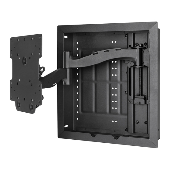
- Page 1 SM-VM-ART1-IW-M Strong™ VersaMount™ Single-Arm In-Wall Articulating Mount SM-VM-ART1-IW-M INSTALLATION MANUAL...
- Page 2 Pg. 2...
- Page 3 HARDWARE IMAGE DESCRIPTION ITEM BAG 1 Enclosure Mounting Screw (A) 6 × 40 mm Screw (B) M4 × 20 mm Screw (C) M6 × 20 mm Screw (D) M6 × 40 mm Screw (E) M8 × 20 mm Screw (F) M8 × 40 mm Screw (G) M8 ×...
- Page 4 WARNINGS • These wall mounts are intended for use only with the maximum weight capacities listed below. • Installation by a professional is highly recommended for this product. • Do not begin installation until you thoroughly read and understanding these instructions. •...
- Page 5 Insert the lag bolts (A) into the outer holes at the sides of the enclosure to secure the enclosure to the wood studs. Installing Equipment into the Strong VersaMount The VersaMount allows for a variety of equipment configuration options. Experiment with the equipment knockout configuration to determine the best installation method.
- Page 6 Attaching the Display Adapter Brackets To attach the extension adapters, align the adapter bracket holes with those on the TV-facing side of the adapter plate and secure in place with the included bolts (O). The display adapter brackets can reach VESA patterns up to 400×400 and provide additional flexibility when needed. Reference the examples below for some ways the adapter brackets can be used to achieve various VESA patterns.
- Page 7 Adjusting Display Position Horizontal Level Adjustments • You tightened the locking nuts at the bottom of the arm assembly end plate at the end of the last step. Now loosen them ¼ turn each. This allows you to position the display with minimal effort. • Place a level on top of the display, and rotate the display until it is horizontally level.
-
Page 8: Attach Bezel
Tilt Adjustments Tilt adjustments usually do not require loosening any bolts or screws. The tilt plate fasteners have been pre-adjusted for easy adjustment with most TVs. However, heavier TVs may sag due to the extra weight. Manually adjust the display to your preferred angle, then evenly tighten the lock nuts on each side of the arms using the 10mm socket wrench to prevent the... - Page 9 Dimensions All measurements in inches. 4.48 15.59 13.31 ≈5.7 11.81 19.61 7.87 15.59 15.60 14.29 Pg. 9...
- Page 10 Wirepath Home Systems, LLC, dba “Control4” and/or dba “SnapAV” in the United States and/or other countries. Control4, Snap AV, Strong, Strong Versabox, and WattBox are also registered trademarks or trademarks of Wirepath Home Systems, LLC. Other names and brands may be claimed as the property of their respective owners. All specifications subject to change without notice.
Need help?
Do you have a question about the VersaMount SM-VM-ART1-IW-M and is the answer not in the manual?
Questions and answers