Table of Contents
Advertisement
®
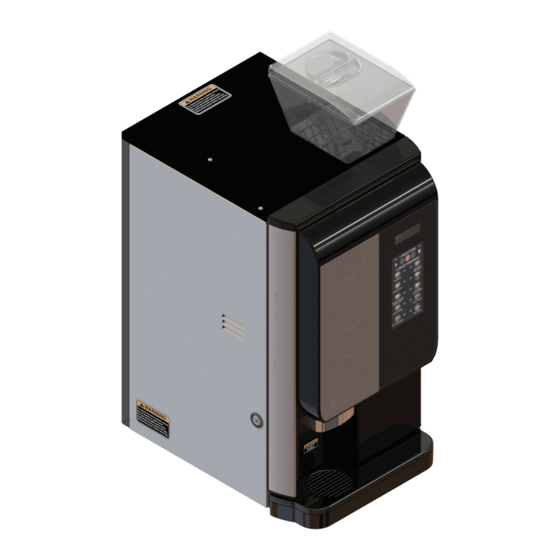
Crescendo
Bean to Cup Espresso System
INSTALLATION & OPERATING GUIDE
For Technical Service, contact Bunn-O-Matic Corporation at 1-800-286-6070.
Bunn-O-Matic Corporation
Post Office Box 3227, Springfield, Illinois 62708-3227
Phone (217) 529-6601 | Fax (217) 529-6644
52384.0001 G 5/21 © 2016 Bunn-O-Matic Corporation
www.bunn.com
Advertisement
Table of Contents

Related Manuals for Bunn Crescendo


Summary of Contents for Bunn Crescendo
- Page 1 ® Crescendo Bean to Cup Espresso System INSTALLATION & OPERATING GUIDE For Technical Service, contact Bunn-O-Matic Corporation at 1-800-286-6070. Bunn-O-Matic Corporation Post Office Box 3227, Springfield, Illinois 62708-3227 Phone (217) 529-6601 | Fax (217) 529-6644 52384.0001 G 5/21 © 2016 Bunn-O-Matic Corporation...
-
Page 2: Warranty
This war- ranty is conditioned on the Buyer 1) giving BUNN prompt notice of any claim to be made under this warranty by telephone at (217) 529-6601 or by writing to Post Office Box 3227, Springfield, Illinois 62708-3227;... -
Page 3: Table Of Contents
Rinse Cycle ........................21 Whipper Components .....................23 Hopper Components .......................24 BI-Weekly Brew Chamber .......................25 PREVENTIVE MAINTENANCE ....................28 ADJUSTMENTS ........................29 DRAINING THE HOT WATER TANKS ..................31 WIRING SCHEMATIC ......................32 TIP: For advanced programming information go to www.bunn.com to obtain the latest information. -
Page 4: North American And Ce Requirements
NORTH AMERICAN REQUIREMENTS • This appliance must be installed in locations where it can be overseen by trained personnel. • For proper operation, this appliance must be installed where the temperature is between 41°F to 95°F (5°C to 35°C). • Appliance shall not be tilted more than 10° for safe operation. •... -
Page 5: User Notices
READ THE ENTIRE No user-serviceable parts inside. OPERATING MANUAL BEFORE Authorized service personnel only. USING THIS PRODUCT Disconnect power before servicing. 00986.0000M 10/14 ©1994 Bunn-O-Matic Corporation 37881.0000 12368.0002 00986.0000 INITIAL SETUP DRIP TRAY, BREW GROUP AND BEAN HOPPER 1. Remove drip tray and cover from the parts box. Attach... -
Page 6: Filling Soluble Hoppers
INITIAL SETUP DRIP TRAY, BREW GROUP AND BEAN HOPPER ( continued) 5. Connect brew chamber outlet tube. 6. Slide red lock to right until it locks. 7. Connect water inlet tube. 8. Remove the bean hopper from the parts box and install in top of machine. - Page 7 INITIAL SETUP FILLING SOLUBLE HOPPERS ( continued) 3. Pull the hopper forward to remove. 4. Set the hoppers on the counter, and push the slide gates on the elbows in to close. 5. Remove hopper lids. 6. Fill hoppers with appropriate soluble products. NOTE: Default menu is milk product left hopper, chocolate is center hopper, and vanilla is right hopper.
-
Page 8: Capacity
INITIAL SETUP CAPACITY 1. Brew chamber has a capacity rating of 5 gm minimum up to 15 gm maximum of espresso grind coffee. 2. Brewer has a peak capacity of 60 single (small) espresso shots per hour. ELECTRICAL REQUIREMENTS CAUTION: The dispenser must be disconnected from the power source until specified in Electrical Hook-Up. -
Page 9: Plumbing Requirements
Bunn-O-Matic does not recommend the use of a saddle valve to install the dispenser. The size and shape of the hole made in the supply line by this type of device may restrict water flow. -
Page 10: Operating Controls And Interface
OPERATING CONTROLS AND INTERFACE 1. Cup Size Buttons: Momentarily pushed to select beverage size to dispense. 2. Dispense Buttons: Momentarily pushed to dispense selected beverage. 3. LED indicators: Illuminates when the adjoining button has been selected. 4. Stop button: Pressing the stop button during dispensing will stop the dispense sequence. OPERATING THE DISPENSER NOTE: The NORMAL/PROGRAM/RINSE switch must be in the NORMAL position. -
Page 11: Modifying The Touch Switch Functions
TIP: A display graphic for single cup dispensing is availble for purchase from BUNN. CREATING A “CUSTOM” BEVERAGE A “CUSTOM” beverage may be edited/created for any dispense switch location. It is recommended that the touch switch graphic insert be replaced with one which matches the beverage reassignments made in this mode. -
Page 12: Recipe Setup
OPERATING CONTROLS AND INTERFACE CREATING A “CUSTOM” BEVERAGE ( continued) ► Set Espresso Shots ( continued) SM BREW VOLUME SM DWELL TIME LG ESP GRIND TIME #.# sec #.# sec Use to Use to Use to Use to Use to Use to Use to Use to... - Page 13 OPERATING CONTROLS AND INTERFACE ► Recipe Setup ( continued) SW 1 LARGE TIME SW 1 SMALL TIME ESPRESSO SHOT? #.# sec #.# sec Use to Use to Use to Use to Use to Use to Use to Use to Use to decrease increase Navigate...
-
Page 14: Touchless Sensitivity Selection Options
TOUCH is “NORMAL”, and the recommended initial setting for TOUCHLESS is “HIGH”. NOTE: Your Crescendo must be fitted with a Gen 2 PCAP with software version 01.20 or higher, and the main I/O board with software version 00.45 or higher to modify the Touch Settings on this machine. -
Page 15: Confirm Beverage Screens
CONFIRM BEVERAGE SCREENS (when activated) Screen text examples for multi-touch and single touch operation of the Crescendo machine. If the CONFIRM BEVERAGE screen is active, it will go there after the beverage is selected and flash the beverage LED until the user selects READY TO BREW the beverage again. -
Page 16: Door Safety Interlock
5. Used coffee puck will now fall through the opening in the chassis. 6. Position the Crescendo so that the opening in the bottom of the machine coincides with the hole in the countertop. 7. To direct the brewing waste water through the counter, disconnect the drain tube from the fitting on the bottom of the espresso drive. -
Page 17: Software Setup
THROUGH COUNTER OPTION Software Setup for Through Counter Option 1. Power the machine. 2. In the PROGRAM mode, use the LARGE cup, (button “A”), to navigate to the “LOCKS/DISABLES” menu. 3. Press the button under “YES” (button “B”) and then the LARGE cup size, (button “A”), until the screen displays the “PUCK BIN”... -
Page 18: General Cleaning
2. Remove the powder mixing chambers, steam traps, frothers and mixing chamber bases. 3. Remove the dispense hoses from the dispense nozzle assembly. 4. Clean all parts removed in warm soapy water. Use Bunn P/N 26367.0000 or 49827.0000 cleaning brush provided to clean bores and orifices. Rinse in cold water. - Page 19 NOTA: Las instucciones de limpieza descritas anteriormente excluyen productos lacteos azucarados. La limpieza de las camaras de mezcla y de los codos de salida de cada tolva deber realizarse diariamente. á 52564.0000 D 4/29/19 © 2015 Bunn-O-Matic Corporation...
-
Page 20: Rinse Cycle
CLEANING RINSE CYCLE (Required Daily) 1. Open the door and place the NORMAL/PROGRAM/RINSE switch in the RINSE position. 2. Close door and place a minimum 400ml container under the dis- pense nozzles. 3. Press the button under RINSE on the screen. SELECT MODE RINSE CLEAN... - Page 21 CLEANING CLEAN CYCLE: Weekly 1. Open the door and place the NORMAL/PROGRAM/RINSE switch in the RINSE position. 2. Press the button under CLEAN on the screen. SELECT MODE RINSE CLEAN 1. SELECT SIZE 3. When the screen prompts ADD CLEANING TABLET, open the dispenser door, and drop a cleaning table into the opening of the ADD CLEANING espresso brew chamber as shown.
- Page 22 CLEANING CLEAN CYCLE: Weekly (continued) 4. Close dispenser door and place a minimum 500ml container under the dispense nozzles. 5. Press the button under NEXT. 6. When screen displays PRESS DISPENSE TO START, press any beverage dispense button to begin cleaning cycle. PRESS DISPENSE TO START 7.
-
Page 23: Whipper Components
CLEANING WEEKLY: Parts Washing and Sanitizing ► WHIPPER COMPONENTS 1. Push slide gates on the hopper 2. Remove hoppers. 3. Remove the elbow fittings from elbows in to close. both mixing chambers. 4. Rotate tab at bottom of mixing 5. Remove mixing chambers by 6. -
Page 24: Hopper Components
CLEANING WEEKLY: Parts Washing and Sanitizing (continued) 13. Rinse cleaning brush, dip in 14. Replace whipper base. Rotate 15. Replace frother disks. Confirm sanitizing solution, and brush the tab on whipper base clockwise that the arrows are aligned with bores of the dispense nozzles. to the vertical position to lock the flat side of the whipper motor Repeat this procedure for each... -
Page 25: Bi-Weekly
CLEANING WEEKLY: Parts Washing and Sanitizing (continued) ► HOPPER COMPONENTS (continued) Clean all parts in a 3 8. Soak all cleaned parts in sanitiz- 9. Reassemble each hopper. compartment sink. Do not ing solution for 5 minutes, then use any abrasive materials. allow to air dry. - Page 26 CLEANING ► SEPARATING BREW CHAMBER PARTS 1. Slide cake pusher forward. 3. Remove cake pusher. 4. Remove sieve head. 2. Pull sieve head out from brew chamber. ► CLEANING BREW CHAMBER PARTS Gear Channels 1. Brush espresso drive gears. 2. Brush sieve head. 3.
- Page 27 CLEANING (continued) BI-WEEKLY (or Every 1,000 Cycles): Espresso Brew Chamber ► REASSEMBLING GROUP HEAD Correct Incorrect 1. Confirm all gears are aligned, 2. Replace cake pusher in channels. 3. Place sieve head in gear and the slots to put the sieve opening, and push in.
-
Page 28: Preventive Maintenance
Bunn-O-Matic Corporation at 1-800-286-6070. NOTE: Replacement parts or service caused by failure to perform required maintenance is not covered by warranty. Cycle (months) Item Part Number PM KIT, 6 MONTHS CRESCENDO 54866.0000 PM KIT, 12 MONTHS CRESCENDO 54867.0000 ADJUSTMENTS Adjustable Variables Used to Create A Perfect Shot of Espresso Topped with Crema The primary 2 variables that you mostly will adjust to achieve your ideal double shot espresso pour time will be the coffee particle size and the dosage targets. -
Page 29: Adjustments
The particle size of the ground coffee can be adjusted for optimal brewing of the espresso. NOTE: BUNN recommends to rotate knob in 1 click increments to achieve desired coarseness. 1. Turn knob counterclockwise to increase the particle size (coarse) of the ground coffee. - Page 30 ADJUSTMENTS Procedure Setting Grinder Adjustment Screw Back to Factory Setting The procedure for setting the adjustment screw back to a factory setting after dismantling and cleaning the burrs. 1. Bean hopper removed or chute closed. Place switch in Program position. Go to display screen and scroll to “SET ESPRESSO SHOTS” menu.
-
Page 31: Draining The Hot Water Tanks
DRAINING THE HOT WATER TANKS To be performed by qualified service personnel only! 1. Open the door and place the NORMAL/PROGRAM/RINSE switch in the PROGRAM position. (Figure 1) 2. Close the door and place a minimum two liter container under the dispense nozzles. 3. -
Page 32: Wiring Schematic
GROUP HEAD Drawn: KJO NGLE PHASE, 50/60HZ CAPACITIVE Date: 09/10/18 TOUCH SWITCH Colors: 3.0000 B 08/24/2018 © BUNN-O-Matic Corporation CRESCENDO SCHEMATIC 120 VOL TS AC-2WIRE SINGLE PHASE, 60HZ 220-240 VOL TS AC-2WIRE SINGLE PHASE, 50/60HZ 54323.0000 B 08/24/2018 © BUNN-O-Matic Corporation... - Page 33 ELDOM Revision: A ESPRESSO CSW-1 Version: 00 GROUP HEAD CAPACITIVE Drawn: KJO TOUCH SWITCH Date: 08/24/18 Colors: 54323.0001 A 08/24/2018 © BUNN-O-Matic Corporation CRESCENDO SCHEMATIC 120/208 - 240 VOL TS AC-3WIRE SINGLE PHASE, 60HZ 54323.0001 A 08/24/2018 © BUNN-O-Matic Corporation...
Need help?
Do you have a question about the Crescendo and is the answer not in the manual?
Questions and answers