Advertisement
Quick Links
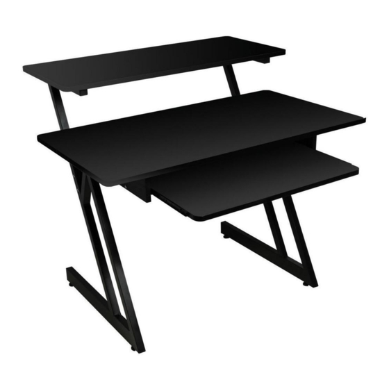
ASSEMBLY INSTRUCTIONS
BEFORE YOU BEGIN: Remove all contents from the boxes.
Assemble the Metal Structure
1. Locate the two holes on the upper horizontal tube. on the left Z-shaped leg (A).
Install one support bar (C) in the upper two holes using two 1.5" Allen head bolts (J)
and two Locking Nuts (K).
2. Install the second support bar (C) in
the two holes located on the left vertical
Z-shaped leg (A).
3. Locate the two holes on the upper
horizontal tube. on the right Z-shaped leg
(Part B). Install one support bar (C) in
the upper two holes using two 1.5" Allen
head bolts (J) and two Locking Nuts (K).
4. Install the second support bar (C) in
the two holes located on the right vertical
Z-shaped leg (A).
5. Locate the four holes on the bottom of
the Legs (A & B). Insert the Feet (O) into
the holes and tighten. Adjust stand to
desired height.
Be sure the stand is placed right side up and it's rubber feet are firmly on the
ground before proceeding with the next step.
Assemble the Upper Work Surface
5. Align the holes in the Upper work surface (D)
with the holes in the metal tabs on the Z-shaped
legs (A&B) (see Figure B). This work surface has
two mounting positions: The rear holes allow the
stand to be flush with wall, and the forward holes
allow for more space on the main work surface.
6. Take 4 Wood Screws (N) and attach the Upper
work surface to the Z-shaped legs (A&B). Do not
over-tighten.
All manuals and user guides at all-guides.com
(Figure A)
Figure A
Figure B
Assemble the Main Work Surface and Keyboard Tray
7. Take both side boards (I), top board (G)
and bottom board (H), and fasten
together with Allen head bolts (L) using
the center holes (see Figure C).
8. Align keyboard tray (F) drawer slide
with the drawer slides on the side boards
(I) and insert the keyboard tray.
9. Take the main work surface (E) and
place it on the floor bottom side up
(see Figure D).
10. Align the holes in the top board (G)
with the four inserts on the main work
surface (E).
11. Take four 1.38" Allen head bolts (M)
and attach the keyboard assembly to the
main work surface.
12. Place the Main work surface (E) with
attached Keyboard tray Assembly on the
metal tabs on the Z-shaped legs (A&B).
Align the holes in the work surface with
the holes in the metal tabs
(see Figure E).
13. Take 4 Wood Screws (J) and attach
the Main work surface (E) to the
Z-shaped legs (A&B).
IMPORTANT: BEFORE USING YOUR STAND, BE SURE THAT ALL BOLTS AND
NUTS ARE FULLY TIGHTENED.
If desired, the height can be adjusted by spinning the small rubber feet
clockwise to lower the height or counter clockwise to raise the height. Place
a level on the main work surface to be sure the Workstation is level before
placing any equipment on the workstation.
WS7500
Figure C
Figure D
Figure E
Advertisement

Related Manuals for on stage WS7500


Summary of Contents for on stage WS7500
- Page 1 All manuals and user guides at all-guides.com ASSEMBLY INSTRUCTIONS WS7500 Assemble the Main Work Surface and Keyboard Tray BEFORE YOU BEGIN: Remove all contents from the boxes. 7. Take both side boards (I), top board (G) and bottom board (H), and fasten...
- Page 2 All manuals and user guides at all-guides.com WS7500 ASSEMBLY INSTRUCTIONS Professional Workstation Congratulations on your purchase of the WS7500 Professional Workstation. Please read the following assembly instructions carefully. We hope you enjoy your new purchase! Parts Also included: Tools Required: >...
Need help?
Do you have a question about the WS7500 and is the answer not in the manual?
Questions and answers