Table of Contents
Advertisement
Quick Links
Advertisement
Table of Contents

Related Manuals for Pioneer PYR009AZFRVBKE


Summary of Contents for Pioneer PYR009AZFRVBKE
- Page 1 UNDER BENCH RV HEAT PUMP AIR CONDITIONER MODEL NO: PYR009AZFRVBKE Owner’s Manual Installation Operation Maintenance IMPORTANT NOTICE: Please read this manual carefully before installing or operating your new air conditioning system. Be sure to save this manual for future reference.
-
Page 2: Table Of Contents
NSTRUCTIONAL ANDBOOK Table of Contents I. Operational Instructions...............1 1. Safety Information..............................1 2. Scope and Purpose of is Manual........................2 3. Model Number and Technical Details Identi cation.....................2 4. Description and Illustration of the Machine......................3 5. Best Practices for Optimal Performance.........................4 6. -
Page 3: Operational Instructions
PERATIONAL NSTRUCTIONS Safety Information CAUTION - Read Before You Proceed Electrical Danger Read and Understand All Safety Precautions Prior to Installation For safe operation, it is imperative that the following rules are obeyed: is appliance can only be used by children aged 8 years and above, or by persons with reduced physical, sensory, or mental capabilities, or persons with lack of experience and knowledge, if they have been given supervision or instructions concerning usage of the appliance... -
Page 4: Scope And Purpose Of Is Manual
Model Number and Technical Details Identi cation Interpreting the Rating Label: Technical Speci cations UNDER-BENCH RV AIR CONDITIONER Model POWER: 115V/60Hz/1Ph MODEL NO.: PYR009AZFRVBKE Number COOLING CAPACITY(BTU/h): 9000 SERIAL NUMBER: See Barcode. HEATING CAPACITY(BTU/h): 9000 PARKER DAVIS HVAC INTERNATIONAL, INC. -
Page 5: Description And Illustration Of The Machine
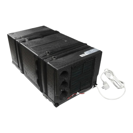
PERATIONAL NSTRUCTIONS Description and Illustration of the Machine e purpose of this machine is to provide greater control of the air temperature within the vehicle that it is installed (such as motor homes, caravans, recreational vehicles, etc.). When the ambient outdoor temperature is hot and humid, it can supply the vehicle with cool and dehumidi ed air via the refrigeration cycle. -
Page 6: Best Practices For Optimal Performance
PERATIONAL NSTRUCTIONS Best Practices for Optimal Performance For best results, the following tips are given in order to improve the output and e ciency of the machine: Increase the vehicle’s insulation amount by sealing o openings and covering glass surfaces with re ective or blackout curtains. When running the machine, select the desired temperature and fan speed and ensure that the air vents are oriented in a suitable and proper direction. -
Page 7: Description Of The Controls
PERATIONAL NSTRUCTIONS Description of the Controls Selecting the Functional Mode: Press the MODE button to cycle between the available states on the machine. After two seconds have elapsed, the system will con rm the selection with an audible beep from the machine’s speaker. Always point the remote controller toward the wall pad when sending commands to ensure the best reception. -
Page 8: Automatic Mode Operation
PERATIONAL NSTRUCTIONS Automatic Mode Operation In AUTO mode, the system manages the Internal T ≥ 77°F T ≤ 68°F 68°F < T < 77°F Temperature compressor, heat pump, and fan speeds entirely autonomously by comparing the Operating Heating, Dehumidi cation, Cooling set temperature with the current internal Mode... -
Page 9: Dehumidi Cation Mode Operation
PERATIONAL NSTRUCTIONS Dehudi cation Mode Operation Dehumidi cation Mode Button Control: Dehumidi cation mode is a limited function that can help reduce the humidity/moisture of the room. However, this system is not intended for use as a dedicated dehumidi er and so this mode should not be left running for very long periods of time. -
Page 10: Heat Pump Mode Operation
PERATIONAL NSTRUCTIONS Heat Pump Mode Heating Mode Button Control: See page 3 for an explanation of Heating Mode functionality. Press the On/O button to switch the machine on or o Press the Change Mode button to select HEAT PUMP mode Use the temperature selection buttons to select a set point between 64 and 86°F Press the fan speed button to select low,... -
Page 11: Timer On And Timer O Mode Operation
PERATIONAL NSTRUCTIONS Timer On and Timer O Mode Operation How to Con gure the Timer O Feature: Press the On/O button to switch the machine on Press the Change Mode button to select the desired operation mode Use the temperature selection buttons to select a set point between 64 and 86°F. -
Page 12: Handling Of The Remote Controller
PERATIONAL NSTRUCTIONS Handling the Remote Controller Installing/Changing the Remote Controller Batteries: Remove the rear battery cover If there are already batteries installed, remove them and insert two fresh AAA size batteries, ensuring to pay attention to the direction of their polarities (+/-). Slide the rear battery cover of the remote back into place. -
Page 13: Routine Maintenance
PERATIONAL NSTRUCTIONS Routine Maintenance Periodic Cleaning Methods: Using a soft and moist cloth, wipe down the surface area of the machine periodically in order to remove dust. Use clean water or a non-aggresive detergent if necessary. Do not use petrol or solvents to clean the machine. -
Page 14: Installation Information
11” - 5/8 Front View 1” - 3/16 15” -11/16 Side View 28” - 7/8 Model Number Unit of Description Measurement PYR009AZFRVBKE Refrigerant Type/Amount See System Nameplate Cooling Capacity BTU/hour 9000 Heating Capacity BTU/hour 9000 Cooling Operational Consumption Amps - Watts 8.8 - 995... -
Page 15: Getting Started
NSTALLATION NSTRUCTIONS Getting Started Installation should only be performed by those with su cient technical knowledge. In addition, the proper tools and equipment should be used for the installation process, to ensure the safety of themselves and those nearby. Unpacking and Handling the System: Observe and follow any special instructions or warnings present Using equal force on both sides, Lift the machine by using only the... -
Page 16: Selecting The Location Of Installation
NSTALLATION NSTRUCTIONS Selecting the Location of Installation In order for the machine to properly provide uniform climate control in the vehicle, it should be installed as close to the center as possible, inside a housing/compartment. Position the machine so as to ensure ease of access, and facillitation of both installation and disassembly. -
Page 17: Preparation Of Floor Openings And Unit Fastening
NSTALLATION NSTRUCTIONS Preparation of Floor Openings and Unit Fastening Clearances and Procedure for Securing the System: Installation of the machine involves creating openings in the oor. ese openings must not be covered or obstructed by parts of the chassis frame or similar xtures. It is also important to block the openings from splashes coming from the wheels, using a splash guard or something similar if necessary. -
Page 18: Securing The System To The Floor
NSTALLATION NSTRUCTIONS Securing the System to the Floor e following pieces of hardware (included) will be used to x the system to the oor: Belt Fastener Bracket Screws Washer ere are three di erent methods of xing the system to the oor using di erent combinations of the above hardware, depending on preference, explained later. -
Page 19: Optional) Creating A Side Cutout For Optimal E Ciency
NSTALLATION NSTRUCTIONS (Optional) Creating a Side Cutout for Optimal E ciency If possible, create an additional cutout on the side of the housing/compartment as depicted below, in order to increase the e ciency at which the system operates. is process is recommended but is not necessary/required. Installation of the Side Cutout Opening: *All measurements in inches LEFT SIDE (A) VIEW... -
Page 20: Fastening The System Into Place
NSTALLATION NSTRUCTIONS Fastening the System Into Place ree Methods Are Available for Fastening: Use the given screws to x the system directly Use the given screws and brackets to x the Use the given screws and washers to x the belts into place, which are used to strap the system onto the pre-assembled spacers on the base belts into place, which are used to strap the system... -
Page 21: Placement Of The Wall Ermostat
NSTALLATION NSTRUCTIONS Placement of the Wall ermostat Locate the wall thermostat, handheld remote controller, batteries, thermostat support bracket, and extension cable. ese items are typically found within the hidden compartment on top of the Cable Outlet Slot system itself during rst installation. A 3/4”... -
Page 22: Recirculation Air Compartment Opening
NSTALLATION NSTRUCTIONS Recirculation Air Compartment Opening Final Cutout Opening for Recirculation Air: Create an additional hole in the compartment where the system is installed, in order to permit recirculation of the internal air. It would be best to locate the cutout near to the front of the machine. -
Page 23: Electrical Hookup
(see technical data and/or nameplate). e installation process is now complete. For any troubleshooting steps, please see Page 22. Simpli ed Wiring Diagram of PYR009AZFRVBKE support@pdhvac.com | (800)-675-7410 | https://www.pdhvac.com/support/... -
Page 24: Troubleshooting, Maintenance, Recycling
ROUBLESHOOTING AINTENANCE ECYCLING Troubleshooting and Diagnosis MALFUNCTION POSSIBLE CAUSES e current temperature is lower than 64°F e set point temperature has been satis ed Defective thermistor or thermal protection If the appliance Low refrigerant is not cooling... e compressor is damaged e heat exchanger coils are dirty e external fan is defective e MODE button is not in the right position... -
Page 25: European Disposal Guidelines
ROUBLESHOOTING AINTENANCE ECYCLING European Disposal Guidelines is appliance contains refrigerant and other potentially hazardous materials. When disposing of this appliance, the law requires special collection and treatment. Do not dispose of this product as household waste or unsorted municipal waste. When disposing of this appliance, you have the following options: •... - Page 26 3250 NW 107 Avenue, Doral, FL 33172 - USA : (305) 513-4488 : (305) 513-4499 E-mail : info@pd-hvac.com Website : www.pd-hvac.com Pioneer product line, parts, and supplies are available online for convenient ordering at: www.highseer.com www.pioneerminisplit.com Scan the below code to visit our support page where you can nd more installation materials: Copyright 2021, Parker Davis HVAC International, Inc., All rights reserved.
Need help?
Do you have a question about the PYR009AZFRVBKE and is the answer not in the manual?
Questions and answers