Table of Contents
Advertisement
Quick Links
1. Product compliance & safety information
These instructions are applicable to the SALUS Controls model stated on the front
cover of this manual only, and must not be used with any other make or model.
This accessory must be fitted by a competent person, and installation must
comply with the guidance provided in the current IEE Wiring Regulations and
current Building Regulations. Failure to comply with the requirements of these
publications could lead to prosecution.
Always isolate the AC Mains supply before installing or working
on any components that require 230 VAC 50Hz supply.
When fitting batteries, do not mix old and new batteries together.
Do not use rechargeable batteries.
Please leave these instructions with the end user where they should be kept in
a safe place for future reference.
02 iT500BM Installer Manual
Advertisement
Table of Contents

Summary of Contents for Salus RXVBC605
- Page 1 1. Product compliance & safety information These instructions are applicable to the SALUS Controls model stated on the front cover of this manual only, and must not be used with any other make or model. This accessory must be fitted by a competent person, and installation must comply with the guidance provided in the current IEE Wiring Regulations and current Building Regulations.
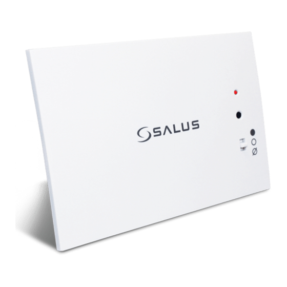
- Page 2 Page 03 - 05 INTRODUCTION The RXVBC605 is an integral plug-in RF boiler control. The RF boiler control is a direct replacement for the basic time clock or blanking plate usually supplied with the boiler. Installing the RF boiler control takes minutes. Once installed, you will benefit from all the control features of the Salus room thermostat.
- Page 3 2. Installation of the boiler module RXVBC605 RXVBC605 RECEIVER For ECOTEC post April 2012 - remove and discard pins. For ECOTEC models prior to April 2012, use as supplied. 1. Switch off the boiler at its main supply. 2. Remove cover panel or existing control.
- Page 4 2. Installation of the boiler module RXVBC605 Before switching the boiler on at its mains supply, ensure the module switch is in the position. To ensure the boiler control is connected properly, please now move the switch to . The boiler should now go on and the LED on the your boiler control should illuminate.
- Page 5 Installing the RF boiler control takes minutes. Once installed, you will benefit from all the control features of the Salus thermostat. INTEGRAL RF BOILER CONTROL The Integral RF boiler control is the RF receiving unit for your thermostat.
- Page 6 2. Installation of the boiler module RXWBC605 RXWBC605 RECEIVER RF Transmission The receiving range between your thermostat and the RF Boiler Control is around 100 metres in open air, however many factors can affect the RF transmission and shorten the operating distance, e.g. shielding by thick walls, foil back plasterboard, metal objects such as filing cabinets, general RF interference, and so on.
- Page 7 2. Installation of the boiler module RXWBC605 RXWBC605 RECEIVER Now locate the boiler control’ s four hooks then press in and down. Replace cover panel A. Replace the front fascia and boiler’ s outer casing. Before switching the boiler on at its mains supply, ensure the module switch is in the OFF position 08 iT500BM Installer Manual...


Need help?
Do you have a question about the RXVBC605 and is the answer not in the manual?
Questions and answers