
Related Manuals for Brooks Instrument GP200 Series


Summary of Contents for Brooks Instrument GP200 Series
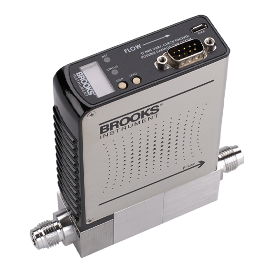
- Page 1 Installation & Operation Manual GP200 Series Metal Sealed Pressure-Based Mass Flow Controllers...
- Page 2 Essential Instructions Read before proceeding! for local sales office contact information. Save this instruction manual for future reference. this warning can result in serious personal injury and / or damage to the equipment. result in serious personal injury and / or damage to the equipment. Connect all products to the proper electrical and pressure sources.
-
Page 3: Table Of Contents
In-Line Filter ............................11 Mechanical Installation ........................11 Flow Controller Installation Arrangement ..................12 Purge the Gas Supply Line Before GP200 Series Installation ............13 Position and Mount the GP200 Series ....................14 Perform a Leak Test..........................17 Zeroing Setup Process ........................17 Zeroing the GP200 Series from the LCD Display Panel ..............18... - Page 4 Figure 2-1 Typical Gas Supply Arrangement ..................13 Figure 2-2 GP200 Series Mounting Attitude Positions ..............15 Figure 2-3 GP200 Series Mounted to K1 Series Substrate Blocks ............ 16 Figure 2-4 Mounting Screws Torque Pattern ..................16 Figure 2-5 GP200 Display showing "%FS" ..................18 Figure 2-6 Top View of GP200 Series Device ...................
-
Page 5: Section 1 Introduction
Section 1 Introduction Introduction The GP200 Series is the first fully (both inlet and outlet) pressure insensitive P-MFC, designed specifically for semiconductor applications. The GP200’s unique differential pressure technology, coupled with its downstream valve architecture, removes the current limitations of pressure-based mass flow controllers, enabling the most precise process gas delivery over the widest range of operating conditions in the industry. -
Page 6: Product Support References
Series. Those documents include: • Brooks Expert Support Tool (BEST) • Brooks GP200 Series Datasheet Notice and Caution Statements Warning, caution, and notice statements are located throughout this manual in the ANSI format. A WARNING statement indicates a potentially hazardous situation which, if not avoided, COULD result in death or serious injury. -
Page 7: Glossary Of Terms And Acronyms
EPI Epitaxy (EPI) A process technology where a pure silicon crystalline structure is deposited or “grown” on a bare wafer, enabling a high-purity starting point for building the semiconductor device. Horizontal Base Down GP200 Series Pressure Based Mass Flow Controller... -
Page 8: Product Description
Setpoint Vertical mounting attitude with inlet side facing up Product Description The GP200 Series is the first fully (both inlet and outlet) pressure insensitive P-MFC, designed specifically for semiconductor applications. The GP200’s unique differential pressure technology, coupled with its downstream valve architecture, removes the... -
Page 9: Specifications For Gp200 Series Devices
High Flow Rate Capability 10 sccm to 50 slm F.S. N2 equivalent P-MFC supports all process flow needs with just nine (9) standard bin configurations for maximum flexibility. Specifications for GP200 Series Devices... -
Page 10: Table 1-3 Specifications For Gp200 Series
Section 1 Introduction Table 1-3 Specifications for GP200 Series... - Page 11 Section 1 Introduction...
-
Page 12: Figure 1-1 Dimensions Of Gp200 Series Downport Configurations
Section 1 Introduction Figure 1-1 Dimensions of GP200 Series Downport Configurations... -
Page 13: Figure 1-2 Dimensions Of Gp200 Series Vcr Configurations
Section 1 Introduction Figure 1-2 Dimensions of GP200 Series VCR Configurations... -
Page 14: Section 2 Installation
If the packing case is damaged, the local carrier should be notified at once regarding his liability. A report should be submitted to the nearest Brooks Instrument location listed on the Global Service Network page on our website: BrooksInstrument.com/GlobalSupportCenters This device has been assembled, calibrated, and double-vacuum bagged in a Class 100 clean room. -
Page 15: Transit Precautions
Section 2 Installation (SDS) for the fluid(s) used in the instrument. Failure to provide this information will delay processing of the instrument. Instrument must have been purged in accordance with the following: Transit Precautions To safeguard against damage during transit, transport the device to the installation site in the same container used for transportation from the factory, if circumstances permit. -
Page 16: Flow Controller Installation Arrangement
Section 2 Installation The recommended installation procedure guidelines are as follows: The device should be in a clean, dry atmosphere relatively • free from shock and vibration. Leave sufficient room for access to the user interface, • display and MAC ID and baud rate switches (if equipped) at the top of the device. -
Page 17: Purge The Gas Supply Line Before Gp200 Series Installation
Purge the Gas Supply Line Before GP200 Series Installation For additional safety, it is recommended to close the two valves between the charged gas line and the GP200 Series to be installed. See Figure above for more details. It is recommended to archive service and calibration documentation for the GP200 Series to determine the contamination state of each gas line and to assist service personnel. -
Page 18: Position And Mount The Gp200 Series
100-120 cycles. Position and Mount the GP200 Series Position the GP200 Series so that the gas flow is pointed in the same direction as the flow arrow shown on the GP200 Series rear label and outer can. The various mounting positions are described in the figure below. -
Page 19: Figure 2-2 Gp200 Series Mounting Attitude Positions
Figure 2-2 GP200 Series Mounting Attitude Positions If your GP200 Series is configured with downport fittings, follow Steps 1 through 4 below. If your GP200 Series has VCR fittings, proceed to Step 5. 1. Refer to Figure 2-3 GP200 Series Mounted to K1 Series Substrate BlocksFigure 2-3 below. -
Page 20: Figure 2-3 Gp200 Series Mounted To K1 Series Substrate Blocks
Section 2 Installation Figure 2-3 GP200 Series Mounted to K1 Series Substrate Blocks Figure 2-4 Mounting Screws Torque Pattern Table 2-1 K1 Series Fasteners Connection Fastener Size K1R2 GP200 to M4 x 34mm M5 x 30mm M5 x 37mm Substrate... -
Page 21: Perform A Leak Test
Perform a Leak Test WARNING It is critical to leak test the gas supply lines and GP200 Series connections before turning on the process gas supply after any new installation. Check for leaks using a helium leak detector or any other appropriate leak test method. -
Page 22: Zeroing The Gp200 Series From The Lcd Display Panel
7. The MFC can now be zeroed. Zeroing the GP200 Series Zeroing the GP200 Series from the LCD Display Panel 1. Once all the conditions outlined in the preparation sections have been met and the pressure across the device is at 0 psid, press the display button until the %FS can be seen on the display as shown in Figure 2-5. -
Page 23: Zeroing Gp200 Series Over Devicenet
Section 2 Installation Figure 2-6 Top View of GP200 Series Device Zeroing GP200 Series Over DeviceNet 1. Once all the conditions outlined in the preparation sections have been met and the pressure across the device is at 0 psid, use the tool interface’s DeviceNet software to send an Explicit... -
Page 24: Performance Checks
This section describes how to zero and sequence the GP200 Series devices for proper operation. If the GP200 Series has been in purge mode for a long period of time, wait until the GP200 Series has cooled down before zeroing. The cool down period should be ~30 minutes for purges up to five minutes and at least 60 minutes after purging overnight. -
Page 25: Using The Brooks Expert Support Tool
Figure 2-8 Standard USB to Micro USB Cable To install the Brooks Expert Support Tool application, download the BEST installer file from the Products/Software section of the Brooks Instrument website (www.brooksinstrument.com). Please reference the Brooks Expert Support Tool Quick Start... -
Page 26: Gp200 Alarms In The Brooks Expert Support Tool
Section 2 Installation DO NOT make any connections to unlabeled connector pins. Any failure to comply could damage the GP200 Series and/or the mating electrical device. Before connecting the cable, make sure that all pin connections of the mating cable have the same pin out connections. When installing and removing cables to and from your computer, make sure the power is turned off on your computer. -
Page 27: Figure 2-10 Gp200 Series Alarm Settings Window In Best
Section 2 Installation Figure 2-10 GP200 Series Alarm Settings Window in BEST GP200 Gas Pages in the Brooks Expert Support Tool Customer gas pages can be changed with the Brooks Expert Support Tool using the Customer Page tab in the Flow... -
Page 28: Gp200 Warping In The Brooks Expert Support Tool
Figure 2-11 Changing Gas Pages using BEST GP200 Warping in the Brooks Expert Support Tool For GP200 devices, an adjustment called “Warping” allows a user to adjust the device’s response to match their standard, such as within a certain environment. The user enters performance data of their device as measured in their environment, then the software uses a curve fit to adjust the device’s response accordingly. -
Page 29: Electrical Connections
Section 2 Installation Figure 2-12 GP200 Warping in the Brooks Expert Support Tool Electrical Connections EtherCAT Connections Power needs to be supplied via the standard male M8 5-pin connector. The M8 connector is located on the upper inlet side of the device. -
Page 30: Devicenet Connections
Section 2 Installation Figure 2-13 GP200 Series EtherCAT M8 Power Connector Figure 2-14 EtherCAT Power Connector Drawing DeviceNet Connections DeviceNet is a 5-wire local network connection that employs a command- response communication protocol for communicating between a master and slave. Obtain a DeviceNet communication cable (Micro M-12) and fasten it to the 5-pin connector. -
Page 31: Analog/Rs485 Connections
DO NOT apply more than 10 Inch-Pounds of torque to the cable coupling when connecting the cable to the device or damage may result to the connector. Analog/RS485 Connections The GP200 Series devices are available with Analog 9-Pin D-Connectors shown below in Figure 2-16. -
Page 32: Figure 2-17 Gp200 Series Analog 9-Pin Connector
Section 2 Installation Figure 2-17 GP200 Series Analog 9-Pin Connector Figure 2-18 GP200 Series Analog 9-Pin Connector (M) -
Page 33: Section 3 Operation
Section 3 Operation General After the device has been properly installed in the process, it is ready for operation. When initiating flow, slowly open any upstream shutoff valve to avoid a flow surge. A bypass is helpful in bringing the flow on smoothly. Avoid starting a pump to supply the device without the use of a valve upstream of the device. -
Page 34: Figure 3-1 Gp200 Series Mfc Architecture
Section 3 Operation Figure 3-1 GP200 Series MFC Architecture The valve block is comprised of the electromagnetic valve as well as the jet/orifice. The jet size is based on the maximum flow rate of the device and increases as you increase in device flow rate. -
Page 35: Figure 3-3 Gp200 Dp Measurement Concept
Section 3 Operation temperature, viscosity, compressibility of the gas, and the geometry of the laminar flow element. Once R is set with N2 calibration, only fluid properties are needed and used for other gases. Figure 3-3 GP200 DP Measurement Concept The gas model is now embedded in the GP200 device and solves the governing fluid mechanics equations in real time at every signal processing cycle (every 2 ms). -
Page 36: Section 4 Maintenance & Troubleshooting
Section 4 Maintenance & Troubleshooting Maintenance & Troubleshooting Overview No routine maintenance is required on the Brooks GP200 Series devices. If an in-line filter is used, the filtering elements should be periodically replaced or cleaned. Any precision unit such as a flow controller requires occasional servicing, especially if it has been operating for an extended period. -
Page 37: Troubleshooting
Series. Therefore, Brooks recommends that you review both the Troubleshooting Checklist and the GP200 Series Troubleshooting Guide before removing the GP200 Series from your system. It is also suggested to contact your Brooks Service representative before removing the GP200 Series from your system. -
Page 38: Gp200 Series Troubleshooting Guide
4. Verify isolations valves are open and the gas supply is turned on. Then verify operating pressures are within operating ranges. 5. Check GP200 Series voltage response by moving the setpoint back and forth. Observe for voltage changes. Table 4-1 Environmental Factors... - Page 39 Is the GP200 Series calibrated for the Check GP200 Series side label. Run a flow check to verify. gas flow? If flow is incorrect, replace the GP200 Series with a unit that is calibrated properly. 5. No gas flow below some set-point.
- Page 40 Equalize the pressure across the GP200 Series by opening it briefly. Set up the GP200 Series for zeroing. Then perform the zeroing procedure in Section 2-14. Is the GP200 Series configured properly Use the tool software to verify.
- Page 41 The tool is commanding a setpoint before the pneumatic valves are opened. GP200 Series and pneumatic timing may be offset. GP200 Series overshoots. 13. Tool display output doesn’t match GP200 Series flow output.
-
Page 42: Section 5 Product Description Code
Overview Section 5 Product Description Code Table 5-1 GP200 Series Model Code Code Description Code Option Option Description I. I. Base Model Code GP200 Ultra-High Purity Pressure-Based Mass Flow Controllers ⁵ II. Valve Configuration Positive Shut-off/Zero Leak-by Valve Normally Closed Valve with Metal Valve Seat ⁶... - Page 43 Section 5 Product Description Code Code Description Code Option Option Description VI. Communications/ Connector EtherCAT Communication 9-Pin D-Connector with Analog/RS485 Communication 9-Pin D-Connector with Analog Only VII. Customer Special Request XXXX Customer Special Request (Consult factory for new requests) VIII. Minimum Inlet Pressure 15 psia minimum inlet pressure, ~15-30 psia inlet pressure range 25 psia minimum inlet pressure, ~25-40 psia inlet pressure range 35 psia minimum inlet pressure, ~35-50 psia inlet pressure range...
-
Page 44: Section 6 Appendix
Section 6 Appendix Appendix A: GP200 Series Patents The GP200 Series is protected by the following US patents and their international filings. • US 11,073,846 B2 “Mass Flow Controller with Absolute and Differential Pressure Transducer” • US 10,705,543 B2 “Mass Flow Controller and Controller... - Page 45 Brooks Instrument can provide customer seminars and dedicated training to engineers, end users and maintenance persons. Please contact your nearest sales representative for more details. Due to Brooks Instrument's commitment to continuous improvement of our products, all specifications are subject to change without notice. TRADEMARKS Brooks is a trademark of Brooks Instrument, LLC All other trademarks are the property of their respective owners.
Need help?
Do you have a question about the GP200 Series and is the answer not in the manual?
Questions and answers