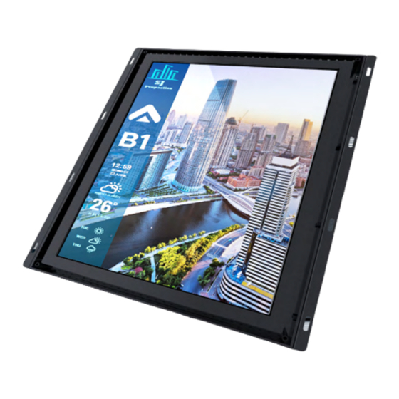
Summary of Contents for AVIRE E-MOTIVE ATOM ATOM01-104-7-40-940
- Page 1 ATOM Cloud-connected high performance multimedia elevator display Installation Guide...
-
Page 2: Before You Start
+ Ethernet Switch (for mulit-lift building connection) + 5m USB Extension Cable Male/Female (133-C-1-0229) Deutschland +44 (0) 1628 540 100 +49 (0) 9721 38656-0 sales.uk@avire-global.com sales.de@avire-global.com E-Motive is a brand of Avire Australia España www.avire-global.com +61 (2) 9669 1102 +34 932 611 760 sales.au@avire-global.com sales.es@avire-global.com... - Page 3 Before Wiring and Mechanical Network Quick setup Technical You start connections installation overview guide specification 1. Wiring Connections & Switches – ATOM EMER IN PWR IN LPBUS USB1 USB2 DIP SWITCH Micro USB Micro SD INPUT PWR OUT 10 11 12 SCREEN SIZE 10.4”...
- Page 4 Before Wiring and Mechanical Network Quick setup Technical You start connections installation overview guide specification 2. Signal Input/Output - MKCAN In/Out Connector Type MC 1,5/4-G-3,5-1844236 Green from Phoenix Contact or equivalent Mating Connector Type MC 1,5/4-ST-3,5-1840382 Green from Phoenix Contact or equivalent Pin 1 - VCAN Supply Input Pin 2 - CANH...
-
Page 5: Mechanical Installation
Before Wiring and Mechanical Network Quick setup Technical You start connections installation overview guide specification Installation guide 2. Mechanical installation Power from external power supply Step by Step Guide Caution 1. Prepare the COP cut-out and mounting studs according to + Risk of electric shock. - Page 6 Display 8 Display 9 Display 16 To other Machine Rooms Cabling not supplied by Avire 1 x Shielded Twisted Pair Cable (AWG 18 or CSA RG6/11 Coaxal Cable, DVB-T RF Signal 0.75mm ), VDSL Solution (up to 1km between network 2 x PVC Wires (AWG 18 or CSA 0.75mm...
- Page 7 Before Wiring and Mechanical Network Quick setup Technical You start connections installation overview guide specification Network overview - Navigation Box Central Location Internet MK-775 DCP Car 1 Car 2 Car 3 Car 4 Navigation Box Navigation Box Navigation Box Navigation Box 11:32 11:32 11:32...
- Page 8 Before Wiring and Mechanical Network Quick setup Technical You start connections installation overview guide specification 3. Quick Setup 3.1 Setup & Configuration - Lift Controller - Serial (E-Motive 4-Wire) 3.1.1 Encoder/Converter Board Wiring and Setup To show lift position and status information on the ATOM, an E-Motive encoder is required. The CX-BASIC is E-Motive’s standard encoder providing a single serial data connection to the ATOM display via 4-wire connection.
- Page 9 Before Wiring and Mechanical Network Quick setup Technical You start connections installation overview guide specification Caution + Risk of electric shock. Never remove the casing of the unit + Ensure that the power supply is connected properly and that the voltage is correct before turning on the unit.
- Page 10 Before Wiring and Mechanical Network Quick setup Technical You start connections installation overview guide specification 3.1.2 Example Wiring Architecture From Power Supply Unit EMER IN PWR IN LPBUS USB1 USB2 DIP SWITCH Micro USB Micro SD INPUT PWR OUT From CX-BASIC (Below) To ATOM Display (Above)
- Page 11 This works by measuring the atmospheric pressure changes at different altitudes, and sending the relevant position through our MKCAN Bus connection directly on the display. The MKCAN Bus line can then be continued onto other Avire Ecosystem devices to save on wiring, or simply terminated at the Navigation Box/Display.
- Page 12 The layout can be edited by using the layout designer software and update via USB or LAN connection. The Layout Designer can be accessed using your Hub account credentials on the following URL: https:/ /layoutdesigner.avire-global.com/login 4.2 On-board menu configuration The ATOM features an on-board programming interface allowing the user to make minor configuration changes such as date, time and time zone configuration.
- Page 13 Date/Time Year Set display date & time settings. Month Note: If the display has a live internet connection, then the date/time will be automatically set using the regional details set in the AVIRE Hub building Hour information. Minute Display Set display location...
-
Page 14: Technical Specifications
Before Before Wiring and Wiring and Mechanical Mechanical Network Network Quick setup Quick setup Technical Technical You start You start connections connections installation installation overview overview guide guide specification specification Technical Specifications SCREEN SIZE 10.4” 12.1” 15.0” 15.6” 18.5” 19.0” 21.5”...


Need help?
Do you have a question about the E-MOTIVE ATOM ATOM01-104-7-40-940 and is the answer not in the manual?
Questions and answers