Table of Contents
Advertisement
Quick Links
Advertisement
Table of Contents

Related Manuals for ACO 3233


Summary of Contents for ACO 3233
- Page 1 Vibration Level Meter TYPE 3233 (Ver 1.3 remote) Operation Manual ACO Co.,Ltd.
- Page 2 Safety precautions Please be sure to fully observe safety precautions This chapter describes several items which we would like you to observe in order to use the product safety and prevent injury to customers and other persons and damage to property. Please be sure to read this Operation Manual and attached documents before use, and fully understand the contents for use.
- Page 3 To reduce risk of injury, take it to a qualified serviceman when service or repair is required. Please contact ACO co. or the dealer when service or repair is required. Do not substitute parts or modify instrument. It causes bodily injury, fire or shock hazard.
- Page 4 3. Cautions for usage Vibration Level Meter TYPE 3233 is assembled with precision parts. To prevent bodily injury or damage to the instrument, the following cautions must be observed. CAUTION Keep the instrument away from the children. If the instrument falls down, it is very dangerous.
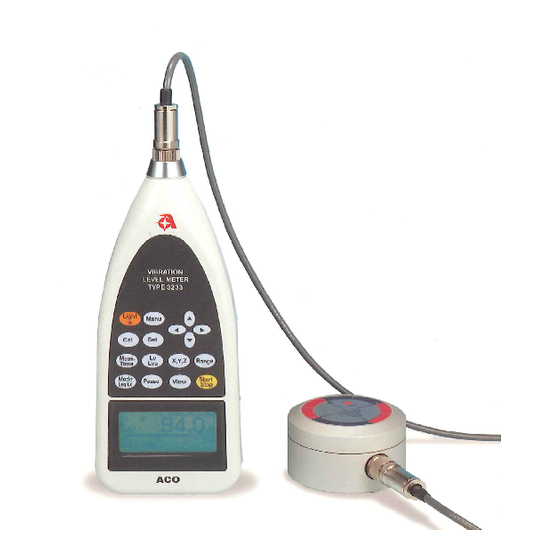
- Page 5 ● Memory function mounted. Approximately 550 pieces of data can be memorized at maximum. ● Eye-friendly and easy-to-look at screen. Large-scale display screen with backlight function. 3. Configuration (1) Vibration Level Meter TYPE 3233 (2) Acceleration pickup TYPE 7833 (3) Cable (3m)
-
Page 6: Table Of Contents
Table of contents Section 1 Preparations 1. Names of each portion P. 6 2. Battery installation P. 7 3. AC power adaptor P. 7 4. LCD Adjustment P. 8 5. Calendar Adjustment P. 9 6. LCD back-light P.10 Section 2 Basic operations 1. -
Page 7: Section 1 Preparations
Section 1 Preparations 1. Names of each portion Threaded retaining ring Female screw for tripod Front panel Displaying portion Battery cover Acceleration pick-up Side panel TYPE7833 Female screw for tripod Side panel Calibration potentiometer AC OUT connector DC OUT connector POWER switch AC power adaptor connector External Input/Output connector... -
Page 8: Battery Installation
2. Battery installation When LCD display tells low battery, install new batteries. For long-term measurement, install new batteries in advance. The following displays tell you the condition of the batteries. Full Replace batteries. To install new batteries: 1)Turn off the POWER switch. 2)The slide is done while pushing the battery lid by the thumb.( Refer to the figure below) 3)Put the new batteries in the case, then shut the cover. -
Page 9: Lcd Adjustment
4. LCD Adjustment You can adjust LCD contrast, when the batteries were low, or when the new batteries were installed.The procedure is as follows. Menu key Cursor key Set key Screen switching key 1) When you press the Menu key, the following screen appears. <menu>... -
Page 10: Calendar Adjustment
5. Calendar Adjustment To adjust the calendar (time), operate as follows. You can adjust calendar in the Menu mode in the same way as LCD adjustment. Menu key 1) When the menu key is inputted, the following menu screen appears. <menu>... -
Page 11: Lcd Back-Light
6. LCD back-light In a case where the display part is hard-to-read in a dark place or at night, it can be read by lighting the backlight on the LCD. Light key 1) When the light key is pressed, the LED on the display part (LCD) lights. 2) The LED turns off by pressing the light key again. -
Page 12: Section 2 Basic Operations
Section 2 Basic operations 1. Switching of display screens and names of each portion 1-1 Switching of display screen The screen has three display mode types of normal screen, 3ch screen and list screen, which can be switched with the screen switching key. The display on the screen is sequentially switched at each time when the screen switching key is pressed. - Page 13 1-2 Display of normal screen →: Display of operating status →: Start Stop key input switches to measuring status ■ : Pause key input switches to temporary stop status 00s: Display of measuring time Displays the time set with Meas Time key. 00h 00m 00s:...
- Page 14 1-3 3ch screen display This mode displays only data for 3ch simultaneously without a bar display. This screen appears by inputting the View key on the normal screen display or list screen display. Vibration level (acceleration level), power level or hour rate vibration level, etc., can be selected with Mode Leq・Lx key, and displayed.
-
Page 15: Operation Of Panel Switches And List Of Functions
1-5 Operation of panel switch and list of functions Cursor key ● Light: Backlight for LCD For details, refer to “Section 1-7. How to use LCD backlight.” ● Menu : Menu key For details, refer to “Section 4-1. Menu operations.” ●... -
Page 16: Calibration
3. Calibration Before starting calibration, it is recommended that the Vibration Level Meter be periodically calibrated.For calibration, there are two types for using the internal oscillator of the Vibration Level Meter, and to calibrate including pick-up by using an agitator. 3-1 Calibration by internal oscillator The oscillator (31.5Hz, sinusoidal wave), which is incorporated in this Vibration Level Meter, allows for calibration. -
Page 17: Section 3 Measuring Operations
Section 3 Measuring operations 1. Measurement of vibration level (Lv) Filter key ch switching key Range key Measurement mode key Screen switching key <Operations> 1) Switch the screen into the normal screen display with the View key. 2) Select the channel to be set with the X, Y, Z key. 3) Select the range in direction with the Range key and set with the Range key. -
Page 18: Measurement Of Vibration Acceleration Level (Lva)
2. Measurement of vibration acceleration level (Lva) This level is the vibration level when the frequency correction is Flat. <Operation> 1) The operation is the same as that in the previous item of “Measurement of vibration level (Lv).” 2) Set with the Lv, Lva key so that the vibration display mode becomes Lva display. <Display>... -
Page 19: Measurement Of Power Average Level (Lveq)
3. Measurement of power average level (Lveq) Filter key ch switching key Range key Start Stop key Measuring mode key Temporary stop key <Operations> Operations are the same as that in the “Measurement of vibration level (Lv).” 1) Select the channel to be set with the X, Y, Z key. Select the range in which approx. -
Page 20: Measurement Of Hour Rate Vibration Level (Lx)
4. Measurement of hour rate vibration level (Lx) <Operation> Hour rate vibration level (Lx): Lvxx or Lvaxx (xx is 05, 10, 90 or 95) 1) Select the measuring item with the Mode Leq・Lx key and Lv・Lva key. 2) Set the measuring time with the Meas. Time key. 3) Press the Start・Stop key to start measurement. -
Page 21: Section 4 Menu Operations
Section 4 Menu operations 1. Menu operations The following menu display screen appears with Menu key input on the panel To return to the measuring screen, input the View key. Menu key Set key Cursor key Pages of <Menu> and <Mode Set> change alternately at each time when the Menu key is inputted. -
Page 22: Description Of Menu Screen
2. Description of menu screen (1/2) <menu> Display of menu items and page Meas Mode : Manu Interval : Single : O f f OUT Ch LCD cont : ***** date y/m/d : 00/01/01 time : 00:00:00 Items Initial value Explanation ●... -
Page 23: Description Of Mode Set Screen
3. Description of mode set screen (2/2) <Mode Set> DC Out Meas time : 1s View : L10 baud rate : 9600 Samp Time : normal ● DC Out: :Setting of output terminal Select the ch outputted from the DC jack. X Y Z ●... -
Page 24: Section 5 Ac, Dc Output
Section 5 AC, DC output 1. AC output Alternate current (AC) signal of which the frequency is corrected is outputted with the following content. Output voltage; 316mVrms (FS), Output resistance; 600Ω, Load resistance; 100kΩ or greater 2. DC output After correction of frequency, direct current (DC) of which the effective value is detected and which is logarithmic-compressed, is outputted. -
Page 25: Section 6 Output To Personal Computer
Section 6 Output to personal computer This Vibration Level Meter has a function to output the measured data or data during measurement to a personal computer. ●Operating system software:Microsoft Windows 98SE/2000/XP/Vista/7 * Windows 7 supports 32bit, 64bit. 1) Collection after measurement Measured data can be collected via a personal computer with a separately sold dedicated cable and software. -
Page 26: Section 7 Specifications
Section 7 Specifications 1) Type Approval No.TW162 2) Model TYPE 3233 3) Product name Vibration Level Meter 4) Conforming standard Measurement Law JIS C 1510-1995 5) Measuring range 30 to 119dB 6) Measuring frequency range 1Hz to 100Hz 7) Pick-up:... -
Page 27: Pin Connections And How To Connect The Extension Cable
Pin Connections and How to Connect the Extension cable 1) Plug the male connector of extension cable into the connector of the body. Mach key ①Mach key groove of body’s connector with the connector of extension cable and insert. ②Push the connector of extension cable. ③Turn the threaded retaining ring a little as shown repeat ②... - Page 28 3) Detach microphone from the body of the meter. Cable The threaded retaining ring ⑦ Turn the threaded retaining ring a little to the left. ⑧ Pull out microphone as shown. ⑨ Repeat ⑦ turn a left and ⑧ pull out a little 5-8 times and you can separate. 4) When the unit is used at places where it is directly exposed to water, such as rainwater, please protect the connector by using self-fusing tape or plastic tape.
- Page 29 <Appendix > Appearance diagram of Vibration Level Meter TYPE3233 connection diagram Extension cable Acceleration pickup Cable(3m) Extension cable (5~100m) TYPE 3233 ※Please connect the extension cable to a cable (3m) between the main body of TYPE 3233.
-
Page 30: Communication Command
DAT CR LF 0Dh 0Ah Data: (ASCII) Variable size Command:1Byte (ASCII) 3. Command table(CMD) Capital letters pertain to PC command Small letters pertain to 3233 command 3233 Function Item ↑ ↑ Function Outline 3233 Time and date setting request T... - Page 31 4. Detail of Command Function Item Type of data Outline of Functions Time and date ASCII(13) YYMMDDHHMMSS setting request Time and date Without data part setting completed Transfer ASCII(6) S A B C D *A, D ; common All CH Configuration file S :CH Setting(1)...
- Page 32 5. Preparation(To Remote mode) Select Remote Mode manually <menu> Meas Mode : Remote Interval : Single : off OUT ch : X LCD cont : ***** Date y/m/d : 00/01/01 : 00:00:00 Time Display changes into [Remote] inhibiting any other key access than Menu. 000h00m00s 100.0 X...
- Page 33 6. Communication timing 6-1 After Power On 3233 Waiting Command Various Command (T,F,S,E,D,C,L,R,A,P) Data and Answer 6-2 Transfer Configuration file 3233 F00000:The following setup will be sent. CH Setting :0 (All Channel) MeasTim :*** Range :110dB Filter :Lv Interval :Single...
- Page 34 : Data acquisition completed command r is issued to PC. ・ In Interval/Repeat mode, r is issued every time of the measurement ・ On E command issued, the measurement is terminated even in the Repeat mode. 3233 Data acquisition completed command r...
- Page 35 On P1 Command (6Byte+CR) X110.0+CR On P0 Command, All CH is sent. X110.0+CR Y110.0+CR Z110.0+CR 6-6 Notes ・Flow control is not available in 3233. ・For communication command error, the ? mark is returned. ・To return to Calibration, Stop measurement command E is used.
- Page 36 Appendix AUTO1 Measurement Guide Getting Started---Setting the Measurement Mode 1. Turn on the POWER switch. 2. Press [Menu] key. The following screen, <menu> page appears. 3. Set the measurement mode (Meas Mode) to Auto1, using cursor keys [▲] [▼] [ ] [ ]. <Mode Set>...
- Page 37 Printing (Data Output) 1. Turn on the POWER switch. 2. Press Menu key to set I/O to Print on page <menu> 1/2. 3. Press Set key. Then <Print> screen is displayed. 4. Select the data you want to be printed out. Selecting List will print the data in listing form as usual.
- Page 38 Vibration Level Meter TYPE 3233 (Ver 1.3 remote) How to Measure Vibration Level using TYPE 3233 ACO Co.,Ltd.
- Page 39 How to install the vibration pick-up How to install the vibration pick-up is provided for by JIS standard 'Method of measuring the vibration level JIS Z 8735 '. ・ Please install the vibration pick-up on flat and firm ground. ( For example. Beaten ground, concrete, and asphalt, etc. ) ・...
- Page 40 Pin Connections and How to Connect the Extension cable 1) Plug the male connector of extension cable into the connector of the body. Mach key ① ② ③ ① Mach key groove of body’s connector with the connector of extension cable and insert. ②...
- Page 41 3) Detach microphone from the body of the meter. Cable The threaded retaining ring ⑧ ⑨ ⑦ ⑦ Turn the threaded retaining ring a little to the left. ⑧ Pull out microphone as shown. ⑨ Repeat ⑦ turn a left and ⑧ pull out a little 5-8 times and you can separate. 4) When the unit is used at places where it is directly exposed to water, such as rainwater, please protect the connector by using self-fusing tape or plastic tape.
- Page 42 This reference sheet describes general Vibration level measurement. It is recommended to calibrate the meter before you start taking measurement. Getting Started Turn on the POWER switch on the side panel. Calibration 1) Press the [Cal] key to switch into calibration status. The Cal lights in the calibration screen. 2) Press the Range key, select 110 dB with the cursor key [▲][▼], and press the [Range] key to register.
- Page 43 Measurement of vibration acceleration level (Lva) Other operations for selecting Lva with the [Lv, Lva] key at the vibration level during frequency correction Flat are completely the same as the measuring operation for vibration level Lv in the previous section. 1) Switch the screen into the normal screen display with the [View] key.
- Page 44 Measurement of hour rate vibration level (Lx) When Lva is selected with the [Lv, Lva] key and the same measurement is performed, an hour rate level for vibration acceleration can be measured. Hour rate vibration level (Lx): Lvxx or Lvaxx (xx is 05, 10, 90 or 95) 1) Select the measuring item with the [Mode Leq・Lx] key and [Lv, Lva] key.
- Page 45 Vibration level meter / Data management software NA-0233-3 This software collects data measured with an Aco Vibration level meter in a PC for processing. The data can be collected after or during measurements. Please choose the method that best suits your needs.
- Page 46 List screen Installation ACO Vibration level meter Copy the folder to the directory you want to use on the hard disk. Start up and Shut down Type3233 When you double click the icon in the folder, the working screen below appears.
- Page 47 Transmitting data after measurement 1. Settings for data measurements <menu> Meas Mode :Manu Interval :Repeat :Off OUT Ch :Off LCD cont :**** Press Menu key date y/m/d :00/11/20 Time :11:30:26 <Mode Set> DC Out 1) Press Menu key , and the menu screen appears. Meas time :*** View...
- Page 48 Transmitting data while making measurements Connect the Vibration level meter and the PC >>Settings on the PC side (The settings are the same as when transmitting data after measurements) >>Settings for and operation of the Vibration level meter <menu> Meas Mode :Manu Interval :Off...
Need help?
Do you have a question about the 3233 and is the answer not in the manual?
Questions and answers