Mitsubishi Electric MELSERVO-J3 Series Instruction Manual
Hide thumbs
Also See for MELSERVO-J3 Series:
- Instruction manual (802 pages) ,
- Manual (668 pages) ,
- Handbook (590 pages)

Related Manuals for Mitsubishi Electric MELSERVO-J3 Series


Summary of Contents for Mitsubishi Electric MELSERVO-J3 Series
- Page 1 General-Purpose AC Servo Series SSCNET Fully Closed Loop Control MODEL MR-J3- B-RJ006 SERVO AMPLIFIER INSTRUCTION MANUAL...
- Page 2 Safety Instructions (Always read these instructions before using the equipment.) Do not attempt to install, operate, maintain or inspect the servo amplifier and servo motor until you have read through this Instruction Manual, Installation guide, Servo motor Instruction Manual (Vol.2) and appended documents carefully and can use the equipment correctly.
- Page 3 1. To prevent electric shock, note the following WARNING Before wiring or inspection, turn off the power and wait for 15 minutes or more until the charge lamp turns off. Then, confirm that the voltage between P( ) and N( ) is safe with a voltage tester and others. Otherwise, an electric shock may occur.
- Page 4 3. To prevent injury, note the follow CAUTION Only the voltage specified in the Instruction Manual should be applied to each terminal, Otherwise, a burst, damage, etc. may occur. Connect the terminals correctly to prevent a burst, damage, etc. Ensure that polarity ( , ) is correct.
- Page 5 CAUTION When you keep or use it, please fulfill the following environmental conditions. Conditions Environment Servo amplifier Servo motor 0 to 55 (non-freezing) 0 to 40 (non-freezing) In operation Ambient 32 to 131 (non-freezing) 32 to 104 (non-freezing) temperature 20 to 65 (non-freezing) 15 to 70 (non-freezing) In storage 4 to 149 (non-freezing)
- Page 6 CAUTION Connect the servo motor power terminal (U, V, W) to the servo motor power input terminal (U, V, W) directly. Do not let a magnetic contactor, etc. intervene. Servo amplifier Servo motor Servo amplifier Servo motor Do not connect AC power directly to the servo motor. Otherwise, a fault may occur. The surge absorbing diode installed on the DC output signal relay of the servo amplifier must be wired in the specified direction.
- Page 7 CAUTION Use the servo amplifier with the specified servo motor. The electromagnetic brake on the servo motor is designed to hold the motor shaft and should not be used for ordinary braking. For such reasons as service life and mechanical structure (e.g. where a ball screw and the servo motor are coupled via a timing belt), the electromagnetic brake may not hold the motor shaft.
- Page 8 About processing of waste When you discard servo amplifier, a battery (primary battery), and other option articles, please follow the law of each country (area). EEP-ROM life The number of write times to the EEP-ROM, which stores parameter settings, etc., is limited to 100,000. If the total number of the following operations exceeds 100,000, the servo amplifier may fail when the EEP- ROM reaches the end of its useful life.
- Page 9 Relevant manuals Manual name Manual No. MELSERVO-J3 Series MR-J3- B Servo Amplifier Instruction Manual SH(NA)030051 MELSERVO-J3 Series Instructions and Cautions for Safe Use of AC Servos IB(NA)0300077 MELSERVO Servo Motor Instruction Manual (Vol.2) SH(NA)030041 EMC Installation Guidelines IB(NA)67310 This Instruction Manual describes the functions unique to the fully closed loop control compatible servo amplifier MR-J3- B-RJ006.
-
Page 10: Table Of Contents
CONTENTS 1. FUNCTIONS AND CONFIGURATION 1 - 1 to 1 -28 1.1 Overview..............................1 - 1 1.2 Control block diagram ..........................1 - 2 1.3 Servo amplifier standard specifications....................1 - 3 1.4 Function list .............................. 1 - 5 1.5 Selecting procedure of control mode....................... 1 - 6 1.5.1 Control mode configuration....................... - Page 11 4.1.5 Setting of feedback pulse electronic gear ..................4 - 4 4.1.6 Confirmation of load side encoder position data................4 - 6 4.1.7 Setting of fully closed loop dual feedback filter ................4 - 7 4.2 Home position return operation ....................... 4 - 8 4.2.1 General precautions..........................
- Page 12 App. 2 Signal layout recording paper ......................App.- 2 App. 3 Change of connector sets to the RoHS compatible products............App.- 3 App. 4 MR-J3-200B-RJ006 servo amplifiers manufactured before March 2008........App.- 4 App. 5 Compliance with the european EC directives................App.- 7 App. 6 Compliance with UL/C-UL standard .....................App.-10...
- Page 13 MEMO...
-
Page 14: Functions And Configuration
1. FUNCTIONS AND CONFIGURATION 1. FUNCTIONS AND CONFIGURATION 1.1 Overview This Instruction Manual explains the product that imports a position feedback signal from a load side encoder, such as a linear encoder, to the MR-J3- B servo amplifier to perform fully closed loop control. A control mode has the semi closed loop control, dual feedback control and fully closed loop control. -
Page 15: Control Block Diagram
1. FUNCTIONS AND CONFIGURATION 1.2 Control block diagram A fully closed loop control block diagram is shown below. The fully closed loop system is controlled in the load side encoder unit. Controller Servo motor Motor side feedback pulse (Motor side) (Load side resolution unit) Droop pulses Linear encoder... -
Page 16: Servo Amplifier Standard Specifications
1. FUNCTIONS AND CONFIGURATION 1.3 Servo amplifier standard specifications (1) 200V class, 100V class Servo amplifier 10B 20B 40B 60B 70B 100B 200B 350B 500B 700B 11KB 15KB 22KB 10B1 20B1 40B1 MR-J3- -RJ006 Item Rated voltage 3-phase 170VAC Rated current [A] 1.1 11.0 17.0 28.0 37.0 68.0 87.0 126.0 1.1 1-phase 100V to... - Page 17 1. FUNCTIONS AND CONFIGURATION (2) 400V class Servo amplifier 60B4 100B4 200B4 350B4 500B4 700B4 11KB4 15KB4 22KB4 MR-J3- -RJ006 Item Rated voltage 3-phase 323VAC Rated current 14.0 17.0 32.0 41.0 63.0 Voltage/frequency 3-phase 380 to 480VAC, 50/60Hz Rated current 10.8 14.4 23.1...
-
Page 18: Function List
1. FUNCTIONS AND CONFIGURATION 1.4 Function list The following table lists the functions of this servo. For details of the functions, refer to the reference field. Function Description Reference High-resolution encoder of 262144 pulses/rev is used as a servo motor High-resolution encoder encoder. -
Page 19: Selecting Procedure Of Control Mode
1. FUNCTIONS AND CONFIGURATION 1.5 Selecting procedure of control mode 1.5.1 Control mode configuration In this servo, a semi closed loop system or fully closed loop system can be selected as a control system. Also, on the fully closed loop system, the semi closed loop control, fully closed loop control and dual feedback control can be switched by the parameter No.PE08 settings. -
Page 20: Model Code Definition
1. FUNCTIONS AND CONFIGURATION 1.6 Model code definition (1) Rating plate AC SERVO Model MR-J3-10B-RJ006 Capacity POWER : 100W Applicable power supply INPUT 0.9A 3PH+1PH200-230V 50Hz 3PH+1PH200-230V 60Hz 1.3A 1PH 200-230V 50/60Hz OUTPUT: 170V 0-360Hz 1.1A Rated output current SERIAL : A34230001 Serial number (2) Model... -
Page 21: Combination With Servo Motor
1. FUNCTIONS AND CONFIGURATION 1.7 Combination with servo motor The following table lists combinations of servo amplifiers and servo motors. The same combinations apply to the models with an electromagnetic brake and the models with a reduction gear. Servo motors Servo amplifier HF-SP HF-KP... -
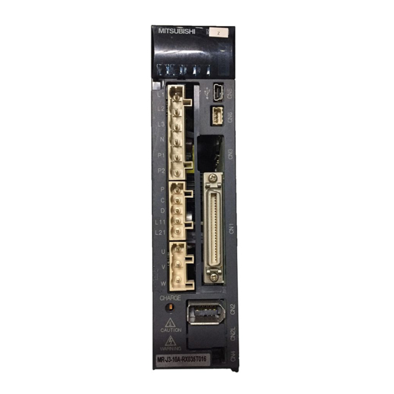
Page 22: Structure
1. FUNCTIONS AND CONFIGURATION 1.8 Structure 1.8.1 Parts identification (1) MR-J3-100B-RJ006 or less Detailed Name/Application explanation Display The 3-digit, seven-segment LED shows the servo status and alarm number. Rotary axis setting switch (SW1) Refer to the Used to set the axis No. of servo amplifier. MR-J3- B Servo Amplifier... - Page 23 1. FUNCTIONS AND CONFIGURATION (2) MR-J3-60B4-RJ006 MR-J3-100B4-RJ006 Detailed Name/Application explanation Display The 3-digit, seven-segment LED shows the servo status and alarm number. Rotary axis setting switch (SW1) Refer to the Used to set the axis No. of servo amplifier. MR-J3- B Servo Amplifier Instruction...
- Page 24 1. FUNCTIONS AND CONFIGURATION (3) MR-J3-200B(4)-RJ006 Detailed Name/Application explanation Display The 3-digit, seven-segment LED shows the servo status and alarm number. Rotary axis setting switch (SW1) Refer to the Used to set the axis No. of servo amplifier. MR-J3- B Servo Amplifier Instruction...
- Page 25 1. FUNCTIONS AND CONFIGURATION (4) MR-J3-350B-RJ006 Detailed Name/Application explanation Display The 3-digit, seven-segment LED shows the servo status and alarm number. Rotary axis setting switch (SW1) Refer to the Used to set the axis No. of servo amplifier. MR-J3- B Servo Amplifier Instruction...
- Page 26 1. FUNCTIONS AND CONFIGURATION (5) MR-J3-350B4-RJ006 MR-J3-500B(4)-RJ006 POINT The servo amplifier is shown without the front cover. For removal of the front cover, refer to section 1.8.2 of the MR-J3- B Servo Amplifier Instruction Manual. Detailed Name/Application explanation Display The 3-digit, seven-segment LED shows the servo status and alarm number.
- Page 27 1. FUNCTIONS AND CONFIGURATION (6) MR-J3-700B(4)-RJ006 POINT The servo amplifier is shown without the front cover. For removal of the front cover, refer to section 1.8.2 of the MR-J3- B Servo Amplifier Instruction Manual. Detailed Name/Application explanation Display The 3-digit, seven-segment LED shows the servo status and alarm number.
- Page 28 1. FUNCTIONS AND CONFIGURATION (7) MR-J3-11KB (4)-RJ006 to MR-J3-22KB(4)-RJ006 POINT The servo amplifier is shown without the front cover. For removal of the front cover, refer to section 1.8.2 of the MR-J3- B Servo Amplifier Instruction Manual. Detailed Name/Application explanation Display The 3-digit, seven-segment LED shows the servo status and alarm number.
-
Page 29: Removal And Reinstallation Of The
1. FUNCTIONS AND CONFIGURATION 1.8.2 Removal and reinstallation of the front cover Before removing or installing the front cover, turn off the power and wait for 15 minutes or more until the charge lamp turns off. Then, confirm that the voltage WARNING between P( ) and N( ) is safe with a voltage tester and others. - Page 30 1. FUNCTIONS AND CONFIGURATION Reinstallation of the front cover Front cover setting tab 1) Insert the setting tabs on the front cover into the 2) Pull up the cover, supporting at point A) . sockets of the servo amplifier (2 places). Setting tab 3) Push the setting tabs until they click.
- Page 31 1. FUNCTIONS AND CONFIGURATION (2) For MR-J3-11KB(4)-RJ006 to MR-J3-22KB(4)-RJ006 Removal of the front cover 1) Press the removing knob on the lower side of the 3) Pull it to remove the front cover. front cover ( A) and B) ) and release the setting tabs.
-
Page 32: Configuration Including Auxiliary Equipment
1. FUNCTIONS AND CONFIGURATION 1.9 Configuration including auxiliary equipment POINT Equipment other than the servo amplifier and servo motor are optional or recommended products. (1) MR-J3-100B-RJ006 or less (a) For 3-phase or 1-phase 200V to 230VAC Personal computer R S T MR Configurator (Note 2) Power supply... - Page 33 1. FUNCTIONS AND CONFIGURATION (b) For 1-phase 100V to 120VAC Personal computer MR Configurator (Note 3) Power supply Servo amplifier No-fuse breaker (NFB) or fuse Junction terminal Magnetic block contactor (Note 1) (MC) Servo system CN1A Power factor controller or Front axis improving servo amplifier CN1B AC reactor...
- Page 34 1. FUNCTIONS AND CONFIGURATION (2) MR-J3-60B4-RJ006 MR-J3-100B4-RJ006 Personal R S T (Note 2) computer Power supply MR Configurator No-fuse breaker Servo amplifier (NFB) or fuse Junction terminal block Magnetic contactor (MC) Servo system CN1A (Note 1) controller or Front axis servo amplifier CN1B Line noise CN1B...
- Page 35 1. FUNCTIONS AND CONFIGURATION (3) MR-J3-200B(4)-RJ006 R S T (Note 2) Power supply No-fuse breaker (NFB) or fuse Magnetic Personal contactor computer (MC) MR Configurator (Note 1) Line noise filter (FR-BSF01) Servo amplifier (Note 1) Power factor improving DC Junction reactor (FR-BEL-(H)) terminal...
- Page 36 1. FUNCTIONS AND CONFIGURATION (4) MR-J3-350B-RJ006 R S T (Note 3) Power supply No-fuse breaker (NFB) or fuse Personal computer MR Configurator Magnetic contactor (MC) Servo amplifier (Note 1) Line noise filter Junction (FR-BLF) terminal block Servo system CN1A controller or Front axis servo amplifier CN1B CN1B Rear servo amplifier...
- Page 37 1. FUNCTIONS AND CONFIGURATION (5) MR-J3-350B4-RJ006 MR-J3-500B(4)-RJ006 R S T (Note 3) Power supply Personal computer MR Configurator No-fuse breaker Servo amplifier (NFB) or fuse Junction Magnetic terminal contactor block (MC) (Note 1) Servo system CN1A Line noise controller or Front axis filter servo amplifier CN1B (FR-BLF)
- Page 38 1. FUNCTIONS AND CONFIGURATION (6) MR-J3-700B(4)-RJ006 R S T Personal computer (Note 3) MR Configurator Power supply No-fuse breaker Servo amplifier (NFB) or fuse Junction terminal Magnetic block contactor (MC) (Note 1) Servo system controller or Front axis CN1A Line noise servo amplifier CN1B filter (FR-BLF)
- Page 39 1. FUNCTIONS AND CONFIGURATION (7) MR-J3-11KB(4)-RJ006 to MR-J3-22KB(4)-RJ006 R S T (Note 3) Personal Power supply computer MR Configurator No-fuse breaker (NFB) or fuse Servo amplifier Magnetic Junction contactor terminal (MC) block (Note 1) Servo system Line noise CN1A controller or Front axis filter servo amplifier CN1B (FR-BLF)
-
Page 40: System Configuration
1. FUNCTIONS AND CONFIGURATION 1.10 System configuration POINT For details of configuration with auxiliary equipments, refer to the MR-J3- B Servo Amplifier Instruction Manual. (1) For a linear encoder Servo amplifier SSCNET controller (Note) Linear encoder with compatible ABZ-phase SSCNET pulse train interface or serial interface position command control signal... - Page 41 1. FUNCTIONS AND CONFIGURATION MEMO 1 - 28...
-
Page 42: Signals And Wiring
2. SIGNALS AND WIRING 2. SIGNALS AND WIRING Any person who is involved in wiring should be fully competent to do the work. Before wiring, turn off the power and wait for 15 minutes or more until the charge lamp turns off. Then, confirm that the voltage between P( ) and N( ) is safe with a voltage tester and others. -
Page 43: Precautions For This Chapter
2. SIGNALS AND WIRING 2.1 Precautions for this chapter The following items are not described in this chapter. Since these descriptions are the same as those of MR- J3- B Servo Amplifier, refer to the MR-J3- B Servo Amplifier Instruction Manual. Item MR-J3- B Servo Amplifier Instruction Manual Explanation of power supply system... - Page 44 2. SIGNALS AND WIRING (1) For 3-phase 200 to 230VAC power supply to MR-J3-10B-RJ006 to MR-J3-350B-RJ006 (Note 4) (Note 8) Trouble Forced stop OFF Controller forced stop Servo amplifier Servo motor (Note 9) CNP1 CNP3 3-phase (Note 7) 200 to Motor 230VAC (Note 1)
- Page 45 2. SIGNALS AND WIRING (2) For 1-phase 200 to 230VAC power supply to MR-J3-10B-RJ006 to MR-J3-70B-RJ006 (Note 4) (Note 8) Trouble Forced stop OFF Controller forced stop Servo amplifier Servo motor (Note 9) CNP1 1-phase CNP3 (Note 7) 200 to 230VAC Motor (Note 1)
- Page 46 2. SIGNALS AND WIRING (3) For MR-J3-10B1-RJ006 to MR-J3-40B1-RJ006 (Note 4) (Note 8) Trouble Forced stop OFF Controller forced stop Servo amplifier Servo motor (Note 9) CNP1 1-phase CNP3 (Note 7) 100 to Blank 120VAC Motor (Note 1) CNP2 (Note 2) (Note 3) Encoder Encoder cable...
- Page 47 2. SIGNALS AND WIRING (4) MR-J3-60B4-RJ006 to MR-J3-200B4-RJ006 (Note 4) (Note 9) Trouble Forced stop OFF Controller forced stop (Note 8) Stepdown transformer Servo amplifier Servo motor (Note 10) CNP1 CNP3 3-phase (Note 7) 380 to Motor 480VAC (Note 1) CNP2 (Note 2) (Note 3)
- Page 48 2. SIGNALS AND WIRING (5) MR-J3-500B-RJ006 MR-J3-700B-RJ006 (Note 9) (Note 4) Forced stop OFF Trouble (Note 8) Cooling fan Controller power supply forced stop Servo amplifier Servo motor (Note 10) 3-phase (Note 7) Built-in 200 to regenerative Motor 230VAC resistor (Note 2) (Note 3) Encoder...
- Page 49 2. SIGNALS AND WIRING (6) MR-J3-350B4-RJ006 to MR-J3-700B4-RJ006 (Note 4) (Note 10) Trouble Forced stop OFF (Note 9) Controller Cooling fan forced stop power supply (Note 8) Stepdown transformer Servo amplifier Servo motor (Note 11) 3-phase (Note 7) Built-in 380 to regenerative Motor 480VAC...
- Page 50 2. SIGNALS AND WIRING Note 1. Always connect P and P . (Factory-wired.) When using the power factor improving DC reactor, refer to chapter 11 of the MR- J3- B Servo Amplifier Instruction Manual. Use only one of power factor improving DC reactor or power factor improving AC reactor.
- Page 51 2. SIGNALS AND WIRING (7) MR-J3-11KB-RJ006 to MR-J3-22KB-RJ006 Servo motor Controller thermal relay forced stop (Note 4) (Note 9) Trouble Forced stop Dynamic Servo amplifier Servo motor brake (Note 10) (Option) 3-phase 200 to 230VAC (Note 7) (Note 2) Regenerative (Note 1) resistor (Note 3)
- Page 52 2. SIGNALS AND WIRING Note 1. Always connect P and P. (Factory-wired.) When using the power factor improving DC reactor, refer to chapter 11 of the MR-J3- B Servo Amplifier Instruction Manual. Use only one of power factor improving DC reactor or power factor improving AC reactor.
- Page 53 2. SIGNALS AND WIRING (8) MR-J3-11KB4-RJ006 to MR-J3-22KB4-RJ006 Servo motor Controller thermal relay forced stop (Note 4) (Note 11) Trouble Forced stop (Note 10) Stepdown transformer Dynamic Servo amplifier Servo motor brake (Note 12) (Option) 3-phase 380 to 480VAC (Note 7) (Note 2) Regenerative (Note 1)
- Page 54 2. SIGNALS AND WIRING Note 1. Always connect P and P. (Factory-wired.) When using the power factor improving DC reactor, refer to chapter 11 of the MR-J3- B Servo Amplifier Instruction Manual. Use only one of power factor improving DC reactor or power factor improving AC reactor.
-
Page 55: I/O Signal Connection Example
2. SIGNALS AND WIRING 2.3 I/O signal connection example POINT For details of each signal, refer to chapter 3 of the MR-J3- B Servo Amplifier Instruction Manual. Servo amplifier (Note 10) (Note 12) (Note 12) 24VDC (Note 2) DICOM 13 MBR Magnetic brake interlock DOCOM In-position... - Page 56 2. SIGNALS AND WIRING Note 1 To prevent an electric shock, always connect the protective earth (PE) terminal ( ) of the servo amplifier to the protective earth (PE) of the control box. 2. Connect the diode in the correct direction. If it is connected reversely, the servo amplifier will be faulty and will not output signals, disabling the emergency stop and other protective circuits.
-
Page 57: Connector And Signal Arrangements
2. SIGNALS AND WIRING 2.4 Connector and signal arrangements POINT The pin configurations of the connectors are as viewed from the cable connector wiring section. The servo amplifier front view shown is for MR-J3-20B-RJ006 or less. For the appearances and connector layouts of other servo amplifiers, refer to chapter 7 OUTLINE DRAWINGS. -
Page 58: Internal Connection Diagram
2. SIGNALS AND WIRING 2.5 Internal connection diagram Servo amplifier Approx. Forced stop 5.6k DICOM (Note 2) (Note 1) Approx. (Note 2) 5.6k 24VDC DICOM DOCOM Differential line driver output <Isolated> (35mA or less) Analog monitor 10VDC VBUS 10VDC Servo motor Encoder Load side encoder CN2L... -
Page 59: Treatment Of Cable Shield External Conductor
2. SIGNALS AND WIRING 2.6 Treatment of cable shield external conductor In the case of the CN2, CN2L and CN3 connectors, securely connect the shielded external conductor of the cable to the ground plate as shown in this section and fix it to the connector shell. External conductor Sheath Core... -
Page 60: Load Side Encoder
3. LOAD SIDE ENCODER 3. LOAD SIDE ENCODER POINT Always use the load side encoder cable introduced in this section. If the other products are used, a faulty may occur. For details of the load side encoder specifications, performance and assurance, contact each encoder manufacturer. -
Page 61: Mitsubishi Serial Interface Compatible Linear Encoder
Part No.09BAA598A: 0.2m When producing a load side 2) Connector set MR-ECNM Part No.09BAA598B: 2m encoder cable (Option manufactured by Mitsubishi Electric Part No.09BAA598C: 3m Corporation) (Refer to section 3.4.) Note. For details, contact with Mitutoyo Corporation. 3 - 2... - Page 62 3. LOAD SIDE ENCODER (b) Production of load side encoder cable Produce the load side encoder cable using MR-EKCBL M-H (10m or less) or MR-ECNM as shown below. The load side encoder cable can be produced as the length of max. 30m. The following diagram shows a connecting example of more than 5m to 10m.
- Page 63 Cable length: 3m Cable length: 2m encoder cable (Option manufactured by Mitsubishi Electric Corporation) (Refer to section 3.4.) (b) Production of load side encoder cable Produce the load side encoder cable using MR-EKCBL M-H (10m or less) or MR-ECNM as shown below.
- Page 64 2) Connector set MR-J3CN2 3) Junction connector (This should be load side encoder (Option manufactured by prepared by the customer.) cable Mitsubishi Electric D-SUB (female) 15 Pin shell: HDAB-15S’ Corporation) Plug case: HDA-CTH (Refer to section 3.4.) (manufactured by HIROSE ELECTRIC CO., LTD)
- Page 65 3. LOAD SIDE ENCODER (b) Production of load side encoder cable Produce the load side encoder cable using MR-J3CN2 or a junction connector as shown below. The load side encoder cable can be produced as the length of max. 30m. The following diagram shows a connecting example of more than 5m to 10m.
-
Page 66: Linear Encoder Manufactured By Heidenhain Corporation
Heidenhain Heidenhain a load side (Option manufactured by should be prepared by Corporation) Corporation) encoder cable Mitsubishi Electric the customer.) (This should be (This should be Corporation) 17-pin coupling (female) prepared by the prepared by the (Refer to section 3.4.) 291697-26 customer.) - Page 67 3. LOAD SIDE ENCODER (b) Production of load side encoder cable Produce the load side encoder cable using MR-J3CN2 or a junction connector as shown below. The load side encoder cable can be produced as the length of max. 30m. The following diagram shows a connecting example of more than 5m to 10m.
- Page 68 (Option manufactured customer.) customer.) encoder cable by Mitsubishi Electric D-SUB15 pin (female) Corporation) (Refer to section 3.4.) Note. For details, contact with Heidenhain Corporation. (b) Production of load side encoder cable Produce the load side encoder cable using MR-J3CN2 or a junction connector as shown below. The load side encoder cable can be produced as the length of max.
-
Page 69: Linear Encoder Manufactured By Sony Manufacturing Systems Corporation (Incremental Type)
Accessories for linear encoder MJ830 or MJ831 MR-J3CN2 Interpolator Cable Length (Option manufactured (This should be prepared PL101-R: 0.3m by Mitsubishi Electric by the customer.) PL101-RH: 3m Corporation) Connector: 10114- (Refer to section 3.4.) 3000PE Shell kit: 10314-52F0- 008 (3M or equivalent) Note. - Page 70 3. LOAD SIDE ENCODER (2) Production of load side encoder cable Produce the load side encoder cable using MR-J3CN2 or a connector for interpolator as shown below. The load side encoder cable can be produced as the length of max. 30m. Supply linear encoder power from external.
-
Page 71: Linear Encoder Manufactured By Renishaw Inc. (Incremental Type)
2) Junction connector (This should be Accessories for linear encoder (Option manufactured by prepared by the customer.) Cable Length Mitsubishi Electric Corporation) D-SUB15 pin (female) 0.5m (Refer to section 3.4.) Note. Produce an encoder cable. An optional cable is not provided... - Page 72 3. LOAD SIDE ENCODER (2) Production of load side encoder cable Produce the load side encoder cable using MR-J3CN2 or a junction connector as shown below. The load side encoder cable can be produced as the length of max. 30m. Connector set (option) MR-J3CN2 Receptacle: 36210-0100PL...
-
Page 73: Abz-Phase Differential Output Load Side Encoder
3. LOAD SIDE ENCODER 3.3 ABZ-phase differential output load side encoder This section describes the connecti on of the ABZ-phase differential output load side encoder. Prepare the MR- J3CN2 connector set for the load side encoder cable and produce it according to the wiring diagram in (3) in this section. - Page 74 3. LOAD SIDE ENCODER (3) Internal wiring diagram For production of the load side encoder cable, use a cable durable against the long period of flexing action. Even though the cable length is max. 30m for the RS-422 communication, the length may be shortened due to the power supply voltage drop or the specifications of linear encoder.
- Page 75 3. LOAD SIDE ENCODER 2) When the consumption current of the load side encoder is more than 350mA POINT When turning on the power, turn on the load side encoder and then turn on the servo amplifier. When turning off the power, turn off the servo amplifier and then turn off the load side encoder.
-
Page 76: Mitsubishi Optional Cable Connector Sets
3. LOAD SIDE ENCODER 3.4 Mitsubishi optional cable connector sets POINT The IP rating indicated is the cable's or connector's protection against ingress of dust and water when the cable or connector is connected to a servo amplifier or servo motor. If the IP rating of the cable, connector, servo amplifier or servo motor vary, the overall IP rating depends on the lowest IP rating of all components. - Page 77 3. LOAD SIDE ENCODER MR-EKCBL M-H Cable model 1) CN2 connector 2) Junction connector MR-EKCBL Connector set: 54599-1019 Housing: 1-172161-9 (Molex or equivalent) Connector pin: 170359-1 (Tyco Electronics or equivalent) (Note) Signal layout Cable clamp: MTI-0002 (Toa Electric Industries) MRR2 Signal layout View seen from wiring side.
-
Page 78: Mr-Ecnm
3. LOAD SIDE ENCODER 3.4.2 MR-ECNM The following shows the connector combination for this connector set. Parts Description Connector set MR-ECNM For CN2 connector Junction connector Connector set: 54599-1019 Housing: 1-172161-9 (Molex) Connector pin: 170359-1 (Tyco Electronics or equivalent) Cable clamp: MTI-0002 (Toa Electric Industries) 3.4.3 MR-J3CN2 The following shows the details of this connector set. - Page 79 3. LOAD SIDE ENCODER MEMO 3 - 20...
-
Page 80: Operation And Functions
4. OPERATION AND FUNCTIONS 4. OPERATION AND FUNCTIONS 4.1 Startup 4.1.1 Startup procedure Start up the fully closed loop system in the following procedure. Completion of installation and wiring Adjustment and operation check in semi closed loop system Check that the servo equipment Positioning operation check using MR Configurator is normal. -
Page 81: Selection Of Fully Closed Loop System
4. OPERATION AND FUNCTIONS 4.1.2 Selection of fully closed loop system By setting parameter No.PA01, PE01 and the control command of controller, the following operations can be made. Semi closed loop control/fully Parameter No. Parameter No. Absolute position closed loop control change Command unit Control method PA01... -
Page 82: Selection Of Load Side Encoder Communication System
4. OPERATION AND FUNCTIONS 4.1.3 Selection of load side encoder communication system The communication system changes depending on the load side encoder type. Refer to 3.1 for the communication system of the load side encoder. Select the cable to be connected to CN2L connector in parameter No.PC26. Parameter No.PC26 Load side encoder cable communication system selection 0: 2-wire type... -
Page 83: Setting Of Feedback Pulse Electronic Gear
4. OPERATION AND FUNCTIONS 4.1.5 Setting of feedback pulse electronic gear POINT If setting a wrong value in the feedback pulse electronic gear (parameter No.PE04, PE05, PE34, PE35), a parameter error (37) and an abnormal operation may occur. Also, a fully closed loop control error (42) may occur during the positioning operation. - Page 84 4. OPERATION AND FUNCTIONS (2) Setting example when using the rotary encoder for the load side encoder of roll feeder Condition Servo motor resolution: 262144pulse/rev Pulley diameter on the servo motor side: 30mm Pulley diameter on the servo motor side: 20mm Rotary encoder resolution: 5000pulse/rev (20000 pulse/rev after multiplication by 4) Driving part...
-
Page 85: Confirmation Of Load Side Encoder Position Data
4. OPERATION AND FUNCTIONS 4.1.6 Confirmation of load side encoder position data Check the load side encoder mounting and parameter settings for any problems. POINT Depending on the check items, the MR Configurator may be used. Refer to section 4.6 for the data displayed on the MR Configurator. When checking the following items, the fully closed loop control mode must be set. -
Page 86: Setting Of Fully Closed Loop Dual Feedback Filter
4. OPERATION AND FUNCTIONS 4.1.7 Setting of fully closed loop dual feedback filter With the initial value (setting = 10) set in parameter No.PE08, make gain adjustment by auto tuning, etc. as in semi closed loop control. While observing the servo operation waveform with the graph function, etc. of the MR Configurator, adjust the dual feedback filter. -
Page 87: Home Position Return Operation
4. OPERATION AND FUNCTIONS 4.2 Home position return operation 4.2.1 General precautions Home position return operation is all performed according to the load side encoder feedback data, independently of the load side encoder type. It is irrelevant to the Z-phase position of the motor encoder. In the case of a home position return using a dog signal, the scale home position (reference mark) must be passed through when an incremental type linear encoder is used, or the Z-phase be passed through when a rotary encoder is used, during a period from a home position return start until the dog signal turns off. - Page 88 4. OPERATION AND FUNCTIONS (2) About proximity dog type home position return using incremental linear encoder (a) When the linear encoder home position (reference mark) exists in the home position return direction When an incremental linear encoder is used, the home position is the position per servo motor revolution to the Linear encoder home position (reference mark) passed through first after a home position return start.
- Page 89 4. OPERATION AND FUNCTIONS (3) About dog type home position return when using the ABZ-phase pulse train specification rotary encoder The home position using a ABZ-phase pulse train specification rotary encoder as a load side encoder is as described below. It is the position per servo motor revolution, starting at the position where the Z-phase of the load side encoder is passed through first after power-on of the servo amplifier.
- Page 90 4. OPERATION AND FUNCTIONS To always make a home position return to the same position, perform the following operation. Once move the rotary encoder to the stroke end opposite to the home position return direction with the JOG operation of controller, etc. and then perform a home position return. Machine position Rotary encoder home position Stroke end...
-
Page 91: Operation From Controller
4. OPERATION AND FUNCTIONS 4.3 Operation from controller The fully closed loop control compatible servo amplifier can be used with any of the following controllers. Servo system controller Model Remarks Q17 DCPU/ Speed control (II) instructions (VVF and VVR) cannot Motion controller Q17 HCPU/ be used. - Page 92 4. OPERATION AND FUNCTIONS (1) When using a linear encoder (unit setting: mm) Load side resolution unit User Controller Servo amplifier Command [mm] Servo motor Linear encoder Position feedback [mm] Electronic gear Speed feedback Differential Motor speed [r/min] Load side resolution unit Calculate the number of pulses (AP) and movement amount (AL) of the linear encoder per ball screw revolution in the following conditions.
-
Page 93: Functions
4. OPERATION AND FUNCTIONS 4.4 Functions 4.4.1 Fully closed loop control error detection If fully closed loop control becomes instable for some reason, the speed at servo motor side may increase abnormally. The fully closed loop control error detection function is a protective function designed to pre-detect it and stop operation. -
Page 94: Auto Tuning Function
4. OPERATION AND FUNCTIONS (b) Position deviation error detection Set " 2" in parameter No.PA03 to make the position deviation error detection valid. Parameter No.PE03 Position deviation error detection Comparing the motor side feedback position (2)) and load side feedback position (4)), if the difference is not less than the set value (1 to 20000kpulse) of parameter No.PE07 (fully closed loop control position deviation error detection level), the function generates an alarm (fully closed loop control error detection (42)) and stops. -
Page 95: Test Operation Mode
4. OPERATION AND FUNCTIONS 4.4.4 Test operation mode Test operation can be performed by combining the MR Configurator software that runs on the personal computer and the servo amplifier. This servo amplifier cannot use motor-less operation. For details on the test operation, refer to the MR-J3- B Servo Amplifier Instruction Manual. Function Item Usability... -
Page 96: About Mr Configurator
4. OPERATION AND FUNCTIONS 4.6 About MR Configurator Using MR Configurator can confirm if the parameter setting is normal or if the servo motor and the load side encoder operate properly. (1) Batch monitor display Select "MR-J3-B fully closed loop" in the system setting of the set-up menu. Name Explanation Unit... - Page 97 4. OPERATION AND FUNCTIONS Name Explanation Unit Peak load ratio The maximum occurrence torque is displayed. The maximum value for the past 15 seconds is displayed considering a rated torque as 100 . Instantaneous torque The instantaneous occurrence torque is displayed. The value of torque being occurred is displayed in real time considering a rated torque as 100 .
- Page 98 4. OPERATION AND FUNCTIONS (2) Fully closed loop diagnostic screen Select the fully closed loop diagnostics of the diagnostics menu. Click "Monitor start" to constantly read the monitor display items from the servo amplifier. Then, click "Monitor stop" to stop reading. Click "Parameter read"...
- Page 99 4. OPERATION AND FUNCTIONS Symbol Name Explanation Unit Encoder information The load side encoder information is displayed. The display contents differ depending on the load side encoder type. ID: The ID No. of the load side encoder is displayed. Data 1: For the incremental type linear encoder, the counter from powering ON is displayed.
- Page 100 4. OPERATION AND FUNCTIONS Symbol Name Explanation Unit Parameter (fully closed loop The parameter for the fully closed loop control is displayed/set. selection) Click "Details" button to display the "Parameter – Fully closed selection" window. 1) Fully closed loop function (Parameter No.PE01) Select "Always valid"...
- Page 101 4. OPERATION AND FUNCTIONS MEMO 4 - 22...
-
Page 102: Parameters
5. PARAMETERS 5. PARAMETERS Never adjust or change the parameter values extremely as it will make operation CAUTION instable. POINT This chapter describes the parameters unique to the fully closed loop control compatible servo amplifier MR-J3- B-RJ006. For the same parameters as those of MR-J3- B servo amplifier, refer to chapter 5 of the MR-J3- B Servo Amplifier Instruction Manual. -
Page 103: Parameter List
5. PARAMETERS 5.1.1 Parameter list Symbol Name Initial value Unit Reference PA01 **STY Control mode 0000h Section 5.1.3 PA02 **REG Regenerative option 0000h Chapter 5 of the MR-J3- B Servo Amplifier Instruction Manual PA03 *ABS Absolute position detection system 0000h Section 5.1.4 PA04 *AOP1... -
Page 104: Parameter Write Inhibit
5. PARAMETERS 5.1.2 Parameter write inhibit Parameter Initial value Unit Setting range Symbol Name PA19 *BLK Parameter write inhibit 000Fh Refer to the text. POINT This parameter is made valid when power is switched off, then on after setting, or when the controller reset has been performed. In the factory setting, this servo amplifier allows changes to the basic setting parameter, gain/filter parameter, extension setting parameter, I/O setting parameter and extension control parameter settings. -
Page 105: Selecting A Control Mode
5. PARAMETERS 5.1.3 Selecting a control mode Parameter Initial value Unit Setting range Symbol Name PA01 **STY Control mode 0000h Refer to the text. POINT This parameter value and switch power off once, then switch it on again to make that parameter setting valid. Select a control mode. -
Page 106: In-Position Range
5. PARAMETERS 5.1.5 In-position range Parameter Initial value Unit Setting range Symbol Name PA10 In-position range pulse 0 to 65535 POINT This parameter cannot be used in the speed control mode. Set the range, where ln position (INP) is output, in the command pulse unit. For the semi closed loop system, set it in the motor encoder unit. - Page 107 5. PARAMETERS (1) For output pulse designation Set " 0 " (initial value) in parameter No.PC03. When parameter No.PC03 has been set to " 1 ", the parameter error (37) occurs. Set the number of pulses per servo motor revolution. Output pulse set value [pulses/rev] For instance, set "5600"...
-
Page 108: Gain/Filter Parameters (No.pb )
5. PARAMETERS 5.2 Gain/filter parameters (No.PB POINT The gain/filter parameter (No.PB ) is the same as that of MR-J3 B servo amplifier. For details, refer to the MR-J3- B Servo Amplifier Instruction Manual. Parameter whose symbol is preceded by * is made valid with the following conditions. - Page 109 5. PARAMETERS Symbol Name Initial value Unit Reference PB40 For manufacturer setting PB41 1125 Chapter 5 of the PB42 1125 MR-J3- B Servo Amplifier Instruction PB43 0004h Manual PB44 PB45 0000h 5 - 8...
-
Page 110: Extension Setting Parameters (No.pc )
5. PARAMETERS 5.3 Extension setting parameters (No.PC POINT Parameter whose symbol is preceded by * is made valid with the following conditions. * : Set the parameter value, switch power off once after setting, and then switch it on again, or perform the controller reset. **: Set the parameter value, switch power off once, and then switch it on again. -
Page 111: List Of Details
5. PARAMETERS 5.3.2 List of details Initial Setting Symbol Name and function Unit value range PC03 *ENRS Encoder output pulse selection 0000h Refer to Use to select the, encoder output pulse direction and encoder output pulse setting. Name function column. Encoder output pulse phase changing Changes the phases of A B-phase encoder output pulses. - Page 112 5. PARAMETERS Initial Setting Symbol Name and function Unit value range PC09 MOD1 Analog monitor 1 output 0000h Refer to Used to selection the signal provided to the analog monitor 1 (MO1) output. (Refer to Name section 5.3.3) function column. Analog monitor 1 (MO1) output selection Setting Item...
- Page 113 5. PARAMETERS Initial Setting Symbol Name and function Unit value range PC26 ** COP8 Function selection C-8 0100h Refer to Used to select the communication system of the serial interface encoder cable to be Name connected to the CN2L connector. function column.
-
Page 114: Analog Monitor
5. PARAMETERS 5.3.3 Analog monitor The servo status can be output to two channels in terms of voltage. (1) Setting Change the following digits of parameter No.PC09,PC10. Parameter No.PC09 Analog monitor (MO1) output selection (Signal output to across MO1-LG) Parameter No.PC10 Analog monitor (MO2) output selection (Signal output to across MO2-LG) Parameters No.PC11 and PC12 can be used to set the offset voltages to the analog output voltages. - Page 115 5. PARAMETERS Setting Output item Description Setting Output item Description CCW direction CCW direction Motor side droop Motor side droop 10[V] 10[V] pulses (Note 1) pulses (Note 1) ( 10V/100 pulses) ( 10V/1000 pulses) 100[pulse] 1000[pulse] 100[pulse] 1000[pulse] 10[V] 10[V] CW direction CW direction CCW direction...
- Page 116 5. PARAMETERS (3) Analog monitor block diagram (fully closed loop) Speed Current Droop pulse Bus voltage command command Current Servo Differential Speed encoder motor command Speed Current Position Position Load side control control encoder command control Encoder Current feedback Servo motor Differential Torque speed...
-
Page 117: I/O Setting Parameters (No.pd )
5. PARAMETERS 5.4 I/O setting parameters (No.PD POINT Parameter whose symbol is preceded by * is made valid with the following conditions. * : Set the parameter value, switch power off once after setting, and then switch it on again, or perform the controller reset. 5.4.1 Parameter list No. -
Page 118: Extension Control Parameters (No.pe )
5. PARAMETERS 5.5 Extension control parameters (No.PE POINT Parameter whose symbol is preceded by * is made valid with the following conditions. * : Set the parameter value, switch power off once after setting, and then switch it on again, or perform the controller reset. **: Set the parameter value, switch power off once, and then switch it on again. -
Page 119: List Of Details
5. PARAMETERS 5.5.2 List of details Initial Setting Symbol Name and function Unit value range PE01 **FCT1 Fully closed loop Selection 1 0000h Refer to Select the semi closed loop control/fully closed loop control. Name Parameter No.PE01 function column. Fully closed loop control selection 0: Always fully closed loop control 1: Selection using the control command of controller Selection using the... - Page 120 5. PARAMETERS Initial Setting Symbol Name and function Unit value range PE06 Fully closed loop control speed deviation error detection level r/min Used to set the speed deviation error detection level of the fully closed loop control error detection. 50000 Valid/invalid of this function can be selected in parameter No.PE03(FCT2).
- Page 121 5. PARAMETERS Initial Setting Symbol Name and Function Unit Value Range PE28 For manufacturer setting 0000h PE29 0000h Do not change this value by any means. PE30 0000h PE31 0000h PE32 0000h PE33 0000h PE34 **FBN2 Fully closed loop control feedback pulse electronic gear 2 numerator Used to set the numerator of the electronic gear to the motor encoder pulse.
-
Page 122: Troubleshooting
6. TROUBLESHOOTING 6. TROUBLESHOOTING POINT Alarms and warnings are basically the same as those of MR-J3- B servo amplifier. This chapter describes the contents different from those of MR-J3- B servo amplifier. As soon as an alarm occurs, make the servo off status and interrupt the main circuit power. -
Page 123: Remedies For Alarms
6. TROUBLESHOOTING 6.2 Remedies for alarms When any alarm has occurred, eliminate its cause, ensure safety, then reset the alarm, and restart operation. Otherwise, injury may occur. CAUTION As soon as an alarm occurs, mark Servo-off and power off the main circuit and control circuit. - Page 124 6. TROUBLESHOOTING Display Name Definition Cause Action Linear encoder Working 1. The temperature of linear encoder is Check the temperature of linear encoder and error 2 environment of linear high. contact with the linear encoder encoder is not manufacturer. normal. 2.
- Page 125 6. TROUBLESHOOTING Display Name Definition Cause Action Load side An error occurs in the 1. CN2L connector is disconnected. Connect correctly. encoder error 1 communication 2. Faulty of the load side encoder Repair or change the cable. between the load cable side encoder and the 3.
-
Page 126: Detailed Explanation Of Linear Encoder Error 1 (2A)
6. TROUBLESHOOTING 6.3 Detailed explanation of linear encoder error 1 (2A) If the cause of Linear encoder error 1(2A) occurrence is not identified, confirm the details shown on the following table according to the alarm detailed information for the alarm history display of MR Configurator, and then contact with the linear encoder manufacturer. - Page 127 6. TROUBLESHOOTING MEMO 6 - 6...
-
Page 128: Outline Drawings
7. OUTLINE DRAWINGS 7. OUTLINE DRAWINGS POINT For the outline drawings of connectors, refer to section 9.2 of the MR-J3- B Servo Amplifier Instruction Manual. For the connector for CN2L, refer to the outline drawings of the connector for CN2 since it is the same as that for CN2. - Page 129 7. OUTLINE DRAWINGS (2) MR-J3-40B-RJ006 MR-J3-60B-RJ006 MR-J3-40B1-RJ006 [Unit: mm] 6 mounting hole Approx. 80 Approx. 170 (Note) CNP1 (Note) CNP2 CNP3 Note. This data applies to the 3-phase or 1-phase 200 to 230VAC power supply models. For 1-phase, 100 to 120VAC power supply, refer to the terminal signal layout. Mass: 1.0 [kg] (2.21 [lb]) Terminal signal layout For 3-phase or...
- Page 130 7. OUTLINE DRAWINGS (3) MR-J3-70B-RJ006 MR-J3-100B-RJ006 [Unit: mm] 6 mounting hole Approx. 80 Air exhaust CNP1 CNP2 CNP3 Cooling fan air intake Mass: 1.4 [kg] (3.09 [lb]) Terminal signal layout Approx. 60 PE terminal CNP1 Screw size: M4 Tightening torque: 1.2 [N m] (10.6 [lb in]) 3-M5 screw CNP2 Approx.
- Page 131 7. OUTLINE DRAWINGS (4) MR-J3-60B4-RJ006 MR-J3-100B4-RJ006 [Unit: mm] Approx. 80 6 mounting hole CNP1 CNP2 CNP3 12 42 Approx. 25.5 Mass: 1.7 [kg] (3.75 [lb]) Terminal signal layout Approx. 60 PE terminal CNP1 Screw size: M4 Tightening torque: 1.2 [N m] (10.6 [lb in]) 3-M5 screw CNP2 Approx.
- Page 132 7. OUTLINE DRAWINGS (5) MR-J3-200B(4)-RJ006 POINT Connectors (CNP1, CNP2, and CNP3) and appearance of MR-J3-200B- RJ006 servo amplifier have been changed from April 2008 production. For existing servo amplifier, refer to appendix 4. [Unit: mm] 6 mounting hole Approx. 80 Air exhaust CNP1 CNP2...
- Page 133 7. OUTLINE DRAWINGS (6) MR-J3-350B-RJ006 [Unit: mm] 6 mounting hole Approx. 80 Air exhaust 21.4 Cooling fan air intake Mass: 2.3 [kg] (5.07 [lb]) Terminal signal layout Approx. 90 PE terminal CNP1 Screw size: M4 Tightening torque: 1.2 [N m] (10.6 [lb in]) 3-M5 screw CNP3 Approx.
- Page 134 7. OUTLINE DRAWINGS (7) MR-J3-350B4-RJ006 MR-J3-500B(4)-RJ006 [Unit: mm] Approx. 80 6 mounting hole 131.5 68.5 Cooling fan air exhaust Terminal layout (Terminal cover open) Cooling fan Air intake 3 places for ground (M4) Mass: 4.6 [kg] (10.1 [lb]) Terminal signal layout Approx.
- Page 135 7. OUTLINE DRAWINGS (8) MR-J3-700B(4)-RJ006 [Unit: mm] 2- 6 mounting hole Approx. 80 Terminal layout Cooling fan (Terminal cover open) air exhaust Cooling fan Air intake 3 places for ground (M4) Mass: 6.2 [kg] (13.7[lb]) Approx. 172 Terminal signal layout Approx.
- Page 136 7. OUTLINE DRAWINGS (9) MR-J3-11KB(4)-RJ006 to 22KB(4)-RJ006 [Unit: mm] Approx. 80 Cooling fan 12 mounting hole air exhaust For MR-J3BAT mounted Rating plate 123.5 Air intake 52 6 26 156 Approx. 260 Approx. 12 Approx. 12 4-M10 screw Mass ([lb]) Servo amplifier MR-J3-11KB(4)-RJ006 18.0 (39.7)
- Page 137 7. OUTLINE DRAWINGS MEMO 7 - 10...
-
Page 138: Appendix
APPENDIX App. 1 Parameter list POINT Parameter whose symbol is preceded by * is made valid with the following conditions. * : Set the parameter value, switch power off once after setting, and then switch it on again, or perform the controller reset. **: Set the parameter value, switch power off once, and then switch it on again. -
Page 139: App. 2 Signal Layout Recording Paper
APPENDIX Extension setting parameters (PC I/O setting parameters (PD Symbol Name Symbol Name PC01 Error excessive alarm level PD01 For manufacturer setting PC02 Electromagnetic brake sequence output PD06 PC03 *ENRS Encoder output pulses selection PD07 *D01 Output signal device selection 1 (CN3-pin 13) PC04 **COP1 Function selection C-1 PD08 *D02... -
Page 140: App. 3 Change Of Connector Sets To The Rohs Compatible Products
APPENDIX App. 3 Change of connector sets to the RoHS compatible products The following connector sets have changed to RoHS compliant since September 2006. RoHS compliant and non-RoHS compliant connector sets may be mixed based on availability. Only the components of the connector set that have changed are listed below. Model Current product RoHS compatible product... -
Page 141: App. 4 Mr-J3-200B-Rj006 Servo Amplifiers Manufactured Before March 2008
APPENDIX App. 4 MR-J3-200B-RJ006 servo amplifiers manufactured before March 2008 Connectors (CNP1, CNP2, and CNP3) and appearance of MR-J3-200B-RJ006 servo amplifier have been changed from April 2008 production. The difference between new MR-J3-200B-RJ006 servo amplifier and existing servo amplifier is described in this appendix. Sections within parentheses in the following sections indicate corresponding sections of the instruction manual. - Page 142 APPENDIX App. 4.2 Configuration including auxiliary equipment (1.9 Configuration including auxiliary equipment) R S T (Note 3) Power supply No-fuse breaker (NFB) or fuse Personal computer MR Configurator Magnetic contactor (MC) Servo amplifier (Note 1) Line noise filter Junction (FR-BSF01) terminal block Servo system...
- Page 143 APPENDIX App. 4.3 Outline drawings (Chapter 7 OUTLINE DRAWINGS) [Unit: mm] 6 mounting hole Approx. 80 Air exhaust 21.4 Cooling fan air intake Mass: 2.3 [kg] (5.07 [lb]) Terminal signal layout Approx. 90 PE terminal CNP1 Screw size: M4 Tightening torque: 1.2 [N m] (10.6 [lb in]) 3-M5 screw CNP3 Approx.
-
Page 144: App. 5 Compliance With The European Ec Directives
APPENDIX App. 5 Compliance with the european EC directives App. 5.1 What are EC directives? The EC directives were issued to standardize the regulations of the EU countries and ensure smooth distribution of safety-guaranteed products. In the EU countries, the machinery directive (effective in January, 1995), EMC directive (effective in January, 1996) and low voltage directive (effective in January, 1997) of the EC directives require that products to be sold should meet their fundamental safety requirements and carry the CE marks (CE marking). - Page 145 APPENDIX (3) Environment (a) Operate the servo amplifier at or above pollution degree 2 set forth in IEC/EN 60664-1. For this purpose, install the servo amplifier in a control box which is protected against water, oil, carbon, dust, dirt, etc. (IP54). (b) Environment Environment Conditions...
- Page 146 APPENDIX (6) Wiring (a) The cables to be connected to the terminal block of the servo amplifier must have crimping terminals provided with insulating tubes to prevent contact with adjacent terminals. Insulating tube Cable Crimping terminal (b) Use the servo motor side power connector which complies with the IEC/EN Standard. The IEC/EN Standard-compliant power connector sets are available from us as options.
-
Page 147: App. 6 Compliance With Ul/C-Ul Standard
APPENDIX App. 6 Compliance with UL/C-UL standard This servo amplifier is designed to comply with UL 508C, CSA C22.2 No.14. (1) Servo amplifiers and servo motors used Use the servo amplifiers and servo motors which standard product. Servo motor Servo amplifier HF-KP HF-MP HF-SP... - Page 148 APPENDIX (2) Installation The MR-J3 series have been approved as the products which have been installed in the electrical enclosure. The minimum enclosure size is based on 150 of each MR-J3 combination. And also, design the enclosure so that the ambient temperature in the enclosure is 55 (131 ) or less, refer to the spec manual.
- Page 149 APPENDIX (6) Options, peripheral devices Use the UL/C-UL Standard-compliant products. Use the no-fuse breaker (UL489 Listed MCCB) or a Class T fuse indicated in the table below. No-fuse breaker (Note) Fuse Servo amplifier Current Voltage AC Current Voltage AC MR-J3-10B(1)-RJ006 20B-RJ006 30A frame 5A MR-J3-40B-RJ006 20B1-RJ006 30A frame 10A...
- Page 150 APPENDIX (8) Selection example of wires To comply with the UL/C-UL Standard, use UL-approved copper wires rated at 60/75 (140/167 ) for wiring. The following table shows the wire sizes [AWG] and the crimping terminal symbols rated at 60 (140 ). The sizes and the symbols rated at 75 (167 ) are shown in the brackets.
- Page 151 APPENDIX Table: Recommended crimping terminals Servo amplifier side crimping terminals Symbol (Note 2) Applicable tool Manufacturer Crimping terminal Body Head Dice FVD5.5-4 YNT-1210S (Note 1) b 8-4NS YHT-8S FVD14-6 DH-122 DH-112 YF-1 E-4 YNE-38 FVD22-6 DH-123 DH-113 YPT-60-21 (Note 1) e 38-6 TD-124 TD-112 YF-1 E-4...
- Page 152 APPENDIX (10) Overload protection characteristics An electronic thermal relay is built in the servo amplifier to protect the servo motor and servo amplifier from overloads. The operation characteristics of the electronic thermal relay are shown below. It is recommended to use an unbalanced torque-generated machine, such as a vertical motion shaft, so that unbalanced torque is not more than 70 of the rated torque.
- Page 153 APPENDIX (11) Figure configuration Representative configuration example to conform to the UL/C-UL standard is shown below. The earth wiring is excluded from the figure configuration. Power supply Fuse no-fuse breaker CN1A Command device Encoder cable U, V, W Control panel side Machine side Servo motor Encoder...
- Page 154 REVISIONS *The manual number is given on the bottom left of the back cover. Print Data *Manual Number Revision Mar, 2006 SH(NA)030056-A First edition Nov., 2007 SH(NA)030056-B Safety Instructions 1.To prevent Part of sentences changed electric shock 2.To prevent fire Part of sentences changed 4.Additional Table partially changed...
- Page 155 Print Data *Manual Number Revision Nov., 2007 SH(NA)030056-B Section 2.4 Connector pin layout figure changed Section 3.1 "ST743" and "LC192M" added to linear encoder list and partially changed Section 3.2.1 (1) Linear scale "ST743" added Section 3.2.1 (3) Linear scale "ST743" added in table Section 3.2.1 (4) Connector pin layout figure changed (a) 2)
- Page 156 Print Data *Manual Number Revision May, 2008 SH(NA)030056-C (2) Wiring "Connect the output terminals (U, V, W) correctly. Otherwise, the servo motor will operate improperly" changed to "Connect the wires to the correct phase terminals (U, V, W) of the servo amplifier and servo motor.
- Page 157 Print Data *Manual Number Revision Aug., 2009 SH(NA)030056-D 4. Additional NFB changed to MC in the figure Instructions (2) 4. Additional Figure changed Instructions (5) Conformance with Contents changed in (2)Installation and (3)Short circuit rating UL/C-UL Standard Description of conformance with the standard changed Description of <About the wires used for wiring>...
- Page 158 Print Data *Manual Number Revision Aug., 2009 SH(NA)030056-D Section 2.5 D11 and D12 changed to b contact Section 3.1 Note 3 added Linear encoder SH13 deleted(Production discontinuation) Section 3.2.1 (4) Figure partially changed (c) 1) Section 3.2.2 (1) Reference changed from "(5) in this section" to "(4) in this section" Section 4.3 Description of "Q170MCPU"...
- Page 159 Warranty 1. Warranty period and coverage We will repair any failure or defect hereinafter referred to as "failure" in our FA equipment hereinafter referred to as the "Product" arisen during warranty period at no charge due to causes for which we are responsible through the distributor from which you purchased the Product or our service provider.
- Page 160 MODEL MODEL CODE HEAD OFFICE : TOKYO BLDG MARUNOUCHI TOKYO 100-8310 This Instruction Manual uses recycled paper. SH (NA) 030056-D (0908) MEE Printed in Japan Specifications subject to change without notice.